ppt on nspcl rourkela odisha
•Download as PPTX, PDF•
2 likes•366 views

ppt on nspcl rourkela

Recommended
More Related Content
What's hot
What's hot (20)
Similar to ppt on nspcl rourkela odisha
Similar to ppt on nspcl rourkela odisha (20)
Recently uploaded
Recently uploaded (20)
ppt on nspcl rourkela odisha
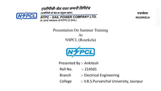
- 1. Presented By :- Ankitesh Roll No. :- 214501 Branch :- Electrical Engineering College :- V.B.S.Purvanchal University, Jaunpur Presentation On Summer Training At NSPCL (Rourkela)
- 2. CONTENTS • INTRODUCTION • LAYOUT OF THE PLANT • SITE SELECTION OF THE PLANT • SELECTION OF FUEL • COAL HANDLING PLANT • DEMINERALISATION PLANT • COMPONENTS USED IN THE PLANT • SWITCHYARD • CONTROL ROOM • REFERENCES
- 3. INTRODUCTION • NSPCL (NTPC-SAIL Power Company Limited) is a joint venture . • NTPC and SAIL joined in March 2001. • CPP (consisting of 2*60 MW generators each) located at the Rourkela Steel Plant and Durgapur Steel Plant. • Bhilai 2*250MW generators. • Rourkela Captive Power Plant (i) NSPCL Rourkela is located in the premises of Rourkela Steel Plant. (ii)The power plant is one of the coal based power plant of Rourkela.
- 4. Fig. 1 Rourkela Captive Power Plant
- 5. LAYOUT OF THE PLANT Fig.2 Schematic arrangement of Steam power plant
- 6. SITE SELECTION OF THE PLANT • Transmission of energy. • Cost of real estate and taxes. • Transportation of fuel. • Availability of water. • Disposal of ash. • Reliability of supply. • Pollution and Noise.
- 7. SELECTION OF FUEL • Selection of coal for power plants. • Calorific value. • Weather ability. • Sulphur content. • Grindability Index. • Ash content. • Particle size.
- 8. COAL HANDLING PLAN Fig. 3 Layout of Coal handling plant
- 9. Contd. • COAL HOPPER. • CRUSHER. • COAL MILLS. • Types of Pulverizers (i) Ball and Tube Mill (ii) Ring and Ball • COAL FEEDER. • CONVEYOR BELT. Fig.4 Conveyor belt
- 10. Fig.5 Coal handling plant control panel Fig.6 Crushed coal
- 11. Fig 7 CHP
- 12. DEMINERALISATION PLANT • Activated Carbon Filter: • Cationic Exchanger:- (Ca++ and Mg++ ion) • Anionic Exchanger:- (resin here is OH) • Mixed Bed Type. Fig 8. Anion Exchanger
- 13. Fig.9 Cation exchanger Fig.10 Activated carbon filter
- 14. Boiler • Boiler is an enclosed vessel in which water is heated • Pulverized coal is put in boiler furnace. • Circulated until the water is turned in to steam at the required pressure. • Coal is burned inside the combustion chamber of boiler. • This steam at high pressure and temperature is used directly
- 15. Water tube boilers • In these boilers water is inside the tubes and hot gases are outside the tubes. • They consists of drums and tubes. • Feed water enters the boiler to one drum . • Greater efficiency. • Large heating surfaces can be obtained by use of large number of tubes. • pressure as high as 125 kg/sq cm and temperatures from 315 to 575 centigrade. Fig. 8.2 Water tube boilers
- 16. Inner diameter 1600mm Thickness 100mm Outside diameter 1800mm Overall length 11500mm Steam Capacity 12.6 cu.m Number of boiler drums 02 Boiler drum height from the ground 52m Orientation of water tubes Vertical Table no.1: Boiler Drum Specifications
- 17. Air preheater • The remaining heat of flue gases is utilised by air preheater. • It is a device used in steam boilers to transfer heat from the flue gases to the combustion air before the air enters the furnace. • kept at a place near by where the air enters in to the boiler. • As a consequence, the gases are also sent to the chimney or stack at a lower temperature. Fig.11 Air preheater
- 18. Economiser • Recover some of the heat from the heat carried away in the flue gases up the chimney and utilize for heating the feed • placed in the passage of flue gases in between the exit from the boiler and the entry to the chimney. • The use of economiser results in saving in coal consumption,increase in steaming rate and high boiler efficiency. • needs extra investment and increase in maintenance costs and floor area required . Fig.12 Economiser
- 19. Superheater • A component of a steam-generating unit in which steam,after it has left the boiler drum, is heated above its saturation temperature. • The amount of superheat added to the steam is influenced by rating of the boiler. • consist of one or more stages of tube arranged to effectively transfer heat from the products of combustion. Fig.13 Superheater
- 20. Electrostatic precipitator • It is a device which removes dust or other finely divided particles from flue gases by charging the particles inductively with an electric field • then attracting them to highly charged collector plates • 2 steps process • Corona discharge area where ionization of the gas occurs. • The charged particles drift toward an electrode of opposite sign and are deposited & neutralize. Fig.14 ESP
- 21. I D Fan & F D Fan • IDF (i) Placed at the outlet of boiler (ii) Exhausts all gaseous combustion products or flue gas by creating negative pressure (iii)More susceptible to erosion and corrosion • FDF (i)Supply the air for combustion pushing the air through combustion chamber to the furnace (ii)Most efficient fans in power plants (iii)These are centrifugal fans, uses variable pitch axial fans
- 22. Condenser • Condenser refers here to the shell and tube heat exchanger, phase transition. • water is in short supply an air-cooled condenser is often used. • The purpose is to condense the also to get the condensed steam in the form of pure water, otherwise known as condensate, back to steam generator or (boiler) as boiler feed water. • Condensers are classified as (i) Jet condensers or contact condensers (ii) Surface condensers. • In jet condensers the steam to be condensed mixes with the cooling water and the temperature of the condensate • In surface condensers there is no direct contact between the steam to be condensed and the circulating cooling water.
- 23. Cooling tower • This hot water is passed to cooling towers. • It is a tower- or building-like device in which atmospheric air (the heat receiver) circulates with warmer water • A cooling tower may serve as the heat sink in a conventional thermodynamic process, such as refrigeration process . • Two basic types of cooling towers are commonly used. • One transfers the heat of warm water to cool air by evaporation. • No evaporative cooling towers are classified as air-cooled condensers and as air-cooled heat exchangers,
- 24. Fig.17 Cooling towerFig.15 Cooling tower fans Fig.16 Sectional view of cooling tower
- 25. Impulse Turbine Fig.18 Types of turbines Have fixed nozzle that orients the flow into high speed jets High kinetic energy, results in shaft rotation Drop in the pressure from inlet to outlet increases the expansion rate of steam Steam velocity increases There is a loss of energy due to high exit velocity which is called as carry over velocity
- 26. Alternator Parameter Rating Rated Power 81250 KVA RPM 3000 Insulation Class F Stator voltage 11500 V Rotor voltage 186.6 V Stator current 4879.1 A Rotor current 1550 A Power factor 0.8 Phase connection Y Frequency 50 Hz Cooling hydrogen Temp. 42. oC Fig.19 An Alternator
- 27. ASH HANDLING PLANT • fly ash about 80% • 20% bottom ash • Removal of Bottom-Ash: by spraying water and continuously. • Removal of fly-Ash: Fly ash collected in each of the E.S.P hopper, economizer hopper, air pre heater hopper and stack hopper. • Disposal of Ash Slurry: 3 ash slurry pumps
- 28. Fig.20 Ash Handling Plant
- 29. SWITCH YARD SWITCHYARD EQUIPMENTS: • Isolators • Current transformer • CVT • Lightening arrestor • Earthing switch • Wave traps • Power transformers • Bus reactor • Circuit Breaker • Relays Fig.21 Switchyard
- 30. Isolator Operates under No Load Condition Interlocked with Breakers and Earth Switches Local as well as Remote Operation possible Isolates Sections for Maintenance Used to select Bus Bars Fig.22 Isolator
- 31. CT • To step-down the high magnitude of current to a safe value to incorporate protection . • Current Transformers are used for the instrumentation of power systems. Fig. 23 Current Transformer
- 32. Capacitor Voltage Transformer (CVT) • CVT is used for supplying voltage signal to the measuring instruments and protective relays. • This is also used as coupling capacitor for PLCC. • Primary voltage is applied to a series of capacitors group. The voltage across one of the capacitor is taken to Aux PT. The secondary of the Aux PT is taken for measurement and protection. Fig. 24 CVT
- 33. Lighting Arrestor • To discharge the high voltage surges in the power system due to Lightning to the ground. • Not in circuit in normal operation. • Offers low resistance at abnormal voltages • Fail to provide protection against travelling. • It consists of a spark gap in series with a nonlinear resistor Fig. 25 Surge Arrester
- 34. Circuit Breaker • Parts of a Circuit Breaker:- • Fixed Contact • Movable Contact • Operating Mechanism and control circuit • Arc quenching medium • Types of circuit breakers • Oil CB • Air Blast CB • Vacuum CB • SF6 CB Fig.26 Circuit Breaker
- 35. Bus bar • Bus bars are copper or aluminium bars (generally of rectangular X section) and operate at constant voltage. • The most commonly used bus bar arrangements in substations are: (i) Single bus bar arrangement. (ii) Single bus bar system with sectionalisation. (iii) Double bus bar arrangement. Fig.27 Bus Bars
- 36. Transformers Fig.28 Generator transformer Fig. 29 Station transformer
- 37. Control Room Fig 30. Control Room
- 38. REFERENCES • 1.Materials provided at NSPCL Rourkela, Odisha, India. • 2.http://powerelectrical.blogspot.com/2007/03/thermal-power-plant-layout- and.html. • 3. indianpowersector.gov.in/home/power-station/thermal-power-plant/. • 4.http://powerplantstechnology.blogspot.in/2010/04/steam-turbine-use-in- power-plant.html. • 5. Generation of electrical energy “B R Gupta” page no. 5 and 83.