SlideShare a Scribd company logo
1 of 7
Download to read offline
INTRODUCTORY ENGINEERING NOTES
Y. Dai, J. Waranyuwat, A. Burkit
1. Aerospace Engineering
1.1. Introduction. Aerospace Engineering is a branch of engineering that deals with design, building
and testing of aircraft and spacecraft. It is divided into several subdisciplines, from which the main
ones are listed below:
(1) Aerodynamics
(2) Propulsion
(3) Structural technology
(4) Materials technology
(5) Stability and Control
At UIUC, all of these areas of specialization are covered during the course of an AE Baccalaureate
program, which gives students an opportunity to get introduced to each of these disciplines and to
choose the area of specialization they want to pursue.
1.2. Aerodynamics.
1.2.1. Introduction. Aerodynamics is a subset of Fluid Dynamics and is a study of the flow of air
around objects. Aerodynamics is applied in a variety of industries, ranging from aircraft and automo-
bile design to wind turbine and bicycle equipment design. Since we will study aerospace engineering,
we will be primarily concerned with aerodynamics of aircraft and spacecraft.
Aerodynamics explains the physics behind the flight, defines the forces acting on an aircraft and
enables us to find out performance parameters of the aircraft and flow parameters of the flow around
it. Aerodynamics relies on governing laws of physics, such as principle of mass conservation, Newton’s
second law and principle of energy conservation.
We will cover the following topics in this section:
• Wing terminology
• Principle of continuity
• Bernoulli’s equation
• Lift and Drag, Thrust and Weight
• Performance parameters
• Flow similarity parameters
1.2.2. Wing terminology. When deriving equations later in this section, we need to be familiar with
wing terminology.
1
In the figure above, a top view of the wing is on the left, and a side view of the wing is on the right.
A side view of the wing shows a side cut of the wing, which is called an airfoil.
Aerospace engineers utilize the following conventions:
b - wingspan
S - wing area
LE - leading edge, the edge of the wing going in the flow of air first
TE - trailing edge, the edge of the wing that the air reaches last
c - chord
α - angle of attack
Question 1.2.1 Aspect ratio is a ratio of the square of the wing span to the wing area, or, AR = b2
S .
It is a useful wing parameter that allows to understand the purpose of the aircraft. F-16 fighter jet
has wingspan of 32.8 ft and wing area of 300 sq.ft. Boeing Phantom Eye HALE aircraft has 150 ft
wingspan and approximately 4 ft chord length. You can assume a rectangular wing. Calculate the
aspect ratios of both these aircraft and think about the reasons for why they are different.
1.2.3. Principle of continuity. In aerodynamics, the flow of air is considered a continuum flow since
the scale at which aerodynamics studies the forces and stresses around the aircraft is much larger
than the scale of a separate air molecule. That is, aerodynamics does not study forces between the
molecules, but rather the forces between the air as a whole and the aircraft, particularly its wings.
Thus, the air can be considered a continuous mass.
Another assumption that is made in aerodynamics to simplify the study of flowing air is a notion of a
control volume . The control volume, or V , is an imaginary volume that encloses a finite volume of
air and in which the laws of aerodynamics can be applied. Generally, it is assumed that the control
volume is fixed in space and the air flows through the control volume. It makes it easier to derive and
apply the equations of aerodynamics. The surface of the control volume is called a control surface,
and is denoted as S. The principle of continuity is derived from the principle of mass conservation,
that states that mass is conserved. That is, the mass that enters the control volume should be the
same mass that exits it. In equation form, the principle of continuity looks as follows:
(1)
∂
∂t V
ρdV +
S
ρv · dS = 0
where V is the control volume of interest, S is the surface of this control volume, ρ is the density of
air, and v is velocity of the flow through the control surface. The first integral in the equation denotes
the rate of change of mass inside the control volume and the second integral is the net amount of mass
that flows in and out of the control volume through its surfaces. Equation (1) is called the continuity
equation.
Note that density, ρ, of the flow can change with time, that is why it is inside the time derivative. If
density is not changing with time, the flow is said to be incompressible, otherwise it is compress-
ible. Generally, compressible flow occurs at high speeds of air flow. In this section we will assume
incompressible flow in order to derive a simplified version of the continuity equation.
So, assuming that density is constant, and that the control volume does not change with time, the
first integral becomes zero, and that leaves S ρv · dS = 0.
Assuming a control volume like in Figure 1, where the air flow cannot exit through upper, lower or
side surfaces, we can derive by calculating the dot product between the velocity and the surface area:
(2) ρ1A1v1 = ρ2A2v2
where A1 and A2 are respective surfaces of the control volume. Since we assumed that the flow is
incompressible, ρ1 = ρ2, and we know that A1 = A2.
2
Figure 1. Control volume.
Hence, v1 = v2 from equation (2). This means that the speed with which the air enters the control
volume as shown in Figure 1, will remain the same when the air exits this control volume.
Now define mass flow rate as:
(3) ˙m = ρAv
where ˙m is the mass flow rate, that is, the change of mass per unit time. Thus, restating equation (2):
(4) ˙m1 = ˙m2
Now, if we assume an airfoil in a wind tunnel, as shown in Figure 2, and define a control volume as
the volume inside the wind tunnel from inlet 1 to outlet 3, the principle of continuity will still hold,
yielding:
(5) ˙m1 = ˙m3
(6) ρ1A1v1 = ρ3A3v3
Figure 2. Airfoil in a wind tunnel (schematic).
And assuming incompressible flow:
(7) A1v1 = A3v3
Since we know that A1 > A3, we conclude that v1 < v3. That is, the speed of the air flow in a narrow
section of the wind tunnel is greater than that in a wide section.
Question 1.2.2 Consider a convergent duct with an inlet area A1 = 5 m2. Air enters this duct with
velocity v1 = 10 m/s and leaves the duct exit with a velocity v2 = 30 m/s. Assuming incompressible
flow, what is the area of the duct exit?
3
1.2.4. Bernoulli’s equation. Bernoulli’s equation is derived from Newton’s second law, that states that
force = mass × acceleration, or more generally, force is equal to time rate of change of momentum.
That is,
(8) F =
∂
∂t
(mv)
Applying it to a control volume, we obtain:
(9)
∂
∂t V
ρvdV +
S
(ρv · dS)v = −
S
pdS +
V
ρfdV + Fviscous
where p is the pressure exerted on the surfaces of the control volume, f is the body force on the air
inside the control volume, and Fviscous are the forces resulting from friction on the surfaces of control
volume. Equation (9) is called the momentum equation in integral form. When expanded to x, y
and z coordinates, the previous equation becomes a set of differential equations. This set of equations
is called the momentum equation in differential form. We present the equation for only one of
the dimensions: x-direction, since the other two are analogous.
(10)
∂(ρu)
∂t
+ · (ρu)v = −
∂p
∂x
+ ρfx + (Fx)viscous
where u is the velocity component in x-direction, and
is gradient, or ∂u
∂x + ∂u
∂y + ∂u
∂z , and only ∂u
∂x is non-zero.
In our case, we assume an inviscid flow, which makes (Fx)viscous = 0. Moreover, we can assume
that the body force is negligibly small compared to pressure forces acting on the surfaces, so we can
ignore body forces, that is fx = 0. Also, as before, the flow is incompressible, so ∂(ρu)
∂t becomes
zero. Integrating u∂u
∂x and ∂p, and getting a constant from integrating 0 on the right hand side of the
equation, we obtain:
(11)
1
2
ρu2
+ p = const = p0
or more generally,
(12)
1
2
ρv2
+ pstatic = ptotal
Equation (12) is called Bernoulli’s equation, and states that the total pressure at a point in the
control volume equals to the sum of static and dynamic pressures, where
(13) q = 1/2ρv2
is dynamic pressure.
For our control volume,
(14) pt1 = ps1 + q1 = ps3 + q3 = pt3
Now, using the previous conclusion that v1 < v3, and knowing from Bernoulli’s equation that pt1 = pt3,
we can conclude that when velocity increases at point 3 (i.e. q3 increases), the static pressure ps3
decreases to conserve the total pressure. Thus, the static pressure above the airfoil is less than the
static pressure below it, which will induce an upward force, called lift.
Question 1.2.3 Consider an airfoil in a flow of air, where far ahead of the airfoil, the pressure,
density and velocity are 1.01×10⁵ N/m2, 1.225 kg/m3, and 150 km/h respectively. At a given point A
on the airfoil, the pressure is 9.95 ×10⁴ N/m2. What is the velocity at point A?
4
1.2.5. Lift and Drag, Thrust and Weight. Lift is an aerodynamic force that enables the aircraft to
fly. Lift results from pressure and stress distribution on the airfoil. The other aerodynamic force
that results from pressure distribution on the airfoil is drag. Drag opposes the motion of the aircraft
forward. For a well designed airfoil, drag is much less than lift. The force that enables the motion
of the aircraft forward is called thrust. It is produced by engines of the aircraft. And the last main
force acting on the aircraft is weight. The forces acting on the are summarized in Figure 3 below.
Figure 3. Main aerodynamic forces acting on aircraft.
1.2.6. Performance parameters. Lift can be calculated using formula:
(15) L = qScL
where L - lift force,
q - dynamic pressure,
S - wing area,
and cL - lift coefficient . It is a dimensionless number, and is an important performance parameter
in aircraft design.
Drag is calculated using a similar formula:
(16) D = qScD
where D - drag force,
cD - drag coefficient, and is also an important dimensionless performance parameter.
As mentioned earlier, for a well designed airfoil cL >> cD, that is drag coefficient is usually an order
of magnitude less than lift coefficient. Lift and drag coefficients allow us to evaluate the performance
of different airfoils without knowing their shapes or sizes. These coefficients are one of the main
deliverables in aircraft design reports.
Question 1.2.4 For a Boeing 747-200 in cruise flight at an altitude of 40,000 ft with the wing area
of 5,500 ft2, the following flight conditions have been reported:
air density = 0.00058735 slug/ft3,
true airspeed = 871 ft/s,
lift coefficient = 0.52,
drag coefficient = 0.022.
Calculate the lift force on the aircraft. What is the maximum weight at takeoff for Boeing 747-200?
What is the required thrust power?
5
1.2.7. Flow similarity parameters. When tests on designing new airfoils are conducted, they take place
in wind tunnels, in which the sizes of wing models are much smaller than the full size aircraft wings.
What enables aerospace engineers to use the results from wind tunnel tests to predict full size wing
performance? The flow similarity parameters. There are many parameters that are reported from
wind tunnel tests, but we will focus on two main ones in this section. They are Mach and Reynolds
numbers. These numbers are also dimensionless, but can deliver plenty of information about the flow
of air around the wing. These numbers are used to mimic the conditions under which the wind tunnel
tests were performed. Moreover, they can predict the performance of a full size model based on the
tests on the scaled model.
Mach number is defined as the ratio of the speed of the air flow to the speed of sound.
(17) M =
v
a
where M - Mach number,
v - speed of air flow,
a - speed of sound at that attitude.
The speed of sound varies with altitude, according to a formula:
(18) a = γRT
where γ - specific heat, (usually equal to 1.4),
R - universal gas constant, equal to 287 J/kg/K (1716 ft-lb/slug/oR),
T - temperature at the altitude of interest.
Depending on Mach number, the flow can be:
• Subsonic M < 1
• Transonic 0.8 < M < 1.2
• Supersonic M > 1
• Hypersonic M > 5
Reynolds number is a measure of the viscosity of the flow and is defined as:
(19) Re =
ρvc
µ
where Re - Reynolds number,
ρ - density of the flow,
v - speed of the flow,
c - chord length,
µ - viscosity of the flow. Reynolds number is usually of the magnitude of 106 for an inviscid flow, and
about 104 and lower for a viscous flow.
Question 1.2.5 An aircraft flies at speed of 800 km/h at an altitude of 35,000 ft. The temperature
of the surroundings is -51oC. What is the Mach number at which the aircraft is flying?
Lift and drag coefficients depend on both Mach and Reynolds numbers and also on an angle of attack,
i.e. cL = f(M, Re, α) and cD = g(M, Re, α), and the exact expresisons for cL and cD are difficult
to obtain. However, during wind tunnel tests, the values of lift and drag forces can be obtained
experimentally, and the lift and drag coefficients can be calculated from Equations (15) and (16)
respectively. A visual representation of how lift coefficient varies with angle of attack as shown in
Figure 4 below:
6
Figure 4. Angle of attack vs. lift coefficient
It can be seen that lift coefficient increases as the angle of attack increases, however only to some
point. That point is called a critical angle of attack, or αstall. After this point, stall occurs, that is
no more lift can be generated at that angle of attack. This is a dangerous condition for aircraft flight,
that is why there are plenty of instruments onboard the aircraft that warn the pilot of the approaching
of the angle of attack that will cause stalling.
Question 1.2.6 If the section lift acting on a two-dimensional wing of chord 2 m, flying at 250 km/h
in sea level altitude is 3000 N/m, when the angle of attack is 4o and section lift curve slope is 0.11,
determine the zero lift angle of attack of the wing.
*Note that ρ=1.225 kg/m3 at sea level altitude and lift coefficient varies with angle of attack ac-
cording to cL = k ∗ (α − α0), where k - slope of lift curve, α - angle of attack (in degrees), α0 - zero
lift angle of attack (in degrees).
7

More Related Content

What's hot

Analysis of Ground Effect on a Symmetrical Airfoil
Analysis of Ground Effect on a Symmetrical AirfoilAnalysis of Ground Effect on a Symmetrical Airfoil
Analysis of Ground Effect on a Symmetrical AirfoilIJERA Editor
 
Aerodynamics aeronautics and flight mechanics
Aerodynamics aeronautics and flight mechanicsAerodynamics aeronautics and flight mechanics
Aerodynamics aeronautics and flight mechanicsAghilesh V
 
Chapter 3 linear wave theory and wave propagation
Chapter  3 linear wave theory and wave propagationChapter  3 linear wave theory and wave propagation
Chapter 3 linear wave theory and wave propagationMohsin Siddique
 
Theme 3
Theme 3Theme 3
Theme 3aks29
 
Examples-Answers-all-Sections-2up
Examples-Answers-all-Sections-2upExamples-Answers-all-Sections-2up
Examples-Answers-all-Sections-2upsyed ahmed taran
 
Chapter 3 static forces on surfaces [compatibility mode]
Chapter 3  static forces on surfaces [compatibility mode]Chapter 3  static forces on surfaces [compatibility mode]
Chapter 3 static forces on surfaces [compatibility mode]imshahbaz
 
Chapter 1 met theory
Chapter 1   met theoryChapter 1   met theory
Chapter 1 met theoryblmadmin
 
Theme 1
Theme 1Theme 1
Theme 1aks29
 
LARC_Ivan_Figueroa_AB_V4
LARC_Ivan_Figueroa_AB_V4LARC_Ivan_Figueroa_AB_V4
LARC_Ivan_Figueroa_AB_V4Ivan Figueroa
 
Relative velocity in two dimensions
Relative velocity in two dimensionsRelative velocity in two dimensions
Relative velocity in two dimensionszahraakamel664
 
Chapter 5 -momentum_equation_and_its_applications
Chapter 5 -momentum_equation_and_its_applicationsChapter 5 -momentum_equation_and_its_applications
Chapter 5 -momentum_equation_and_its_applicationsZackRule
 

What's hot (20)

Analysis of Ground Effect on a Symmetrical Airfoil
Analysis of Ground Effect on a Symmetrical AirfoilAnalysis of Ground Effect on a Symmetrical Airfoil
Analysis of Ground Effect on a Symmetrical Airfoil
 
Aerodynamics aeronautics and flight mechanics
Aerodynamics aeronautics and flight mechanicsAerodynamics aeronautics and flight mechanics
Aerodynamics aeronautics and flight mechanics
 
Aerodinamics
AerodinamicsAerodinamics
Aerodinamics
 
Final Term project
Final Term projectFinal Term project
Final Term project
 
aircraft drag reduction
aircraft drag reductionaircraft drag reduction
aircraft drag reduction
 
Chapter 3 linear wave theory and wave propagation
Chapter  3 linear wave theory and wave propagationChapter  3 linear wave theory and wave propagation
Chapter 3 linear wave theory and wave propagation
 
.wave deformation
.wave deformation.wave deformation
.wave deformation
 
Theme 3
Theme 3Theme 3
Theme 3
 
Examples-Answers-all-Sections-2up
Examples-Answers-all-Sections-2upExamples-Answers-all-Sections-2up
Examples-Answers-all-Sections-2up
 
Fm hydrostatics
Fm hydrostaticsFm hydrostatics
Fm hydrostatics
 
Chapter 3 static forces on surfaces [compatibility mode]
Chapter 3  static forces on surfaces [compatibility mode]Chapter 3  static forces on surfaces [compatibility mode]
Chapter 3 static forces on surfaces [compatibility mode]
 
Chapter6
Chapter6Chapter6
Chapter6
 
Chapter 1 met theory
Chapter 1   met theoryChapter 1   met theory
Chapter 1 met theory
 
Theme 1
Theme 1Theme 1
Theme 1
 
LARC_Ivan_Figueroa_AB_V4
LARC_Ivan_Figueroa_AB_V4LARC_Ivan_Figueroa_AB_V4
LARC_Ivan_Figueroa_AB_V4
 
Relative velocity in two dimensions
Relative velocity in two dimensionsRelative velocity in two dimensions
Relative velocity in two dimensions
 
Laminarflow
LaminarflowLaminarflow
Laminarflow
 
Zasady lotu
Zasady lotuZasady lotu
Zasady lotu
 
Compressive flows
Compressive flowsCompressive flows
Compressive flows
 
Chapter 5 -momentum_equation_and_its_applications
Chapter 5 -momentum_equation_and_its_applicationsChapter 5 -momentum_equation_and_its_applications
Chapter 5 -momentum_equation_and_its_applications
 

Similar to Course textbook sample

A Good Effect of Airfoil Design While Keeping Angle of Attack by 6 Degree
A Good Effect of Airfoil Design While Keeping Angle of Attack by 6 DegreeA Good Effect of Airfoil Design While Keeping Angle of Attack by 6 Degree
A Good Effect of Airfoil Design While Keeping Angle of Attack by 6 Degreepaperpublications3
 
ENG687 Aerodynamics.docx
ENG687 Aerodynamics.docxENG687 Aerodynamics.docx
ENG687 Aerodynamics.docx4934bk
 
Aerodynamic,rotor design and rotor performance of horizontal axis wind turbin...
Aerodynamic,rotor design and rotor performance of horizontal axis wind turbin...Aerodynamic,rotor design and rotor performance of horizontal axis wind turbin...
Aerodynamic,rotor design and rotor performance of horizontal axis wind turbin...Sarmad Adnan
 
Subsonic Airplane Design
Subsonic Airplane DesignSubsonic Airplane Design
Subsonic Airplane Designahmad bassiouny
 
AERODYNAMICS FORCES AND MOMENTS.ppt
AERODYNAMICS FORCES AND MOMENTS.pptAERODYNAMICS FORCES AND MOMENTS.ppt
AERODYNAMICS FORCES AND MOMENTS.ppttauraimamire
 
Analysis Of Owl-Like Airfoil Aerodynamics At Low Reynolds Number Flow
Analysis Of Owl-Like Airfoil Aerodynamics At Low Reynolds Number FlowAnalysis Of Owl-Like Airfoil Aerodynamics At Low Reynolds Number Flow
Analysis Of Owl-Like Airfoil Aerodynamics At Low Reynolds Number FlowKelly Lipiec
 
Avb 2: Aerodynamics - CCPL G. Fleming
Avb 2: Aerodynamics - CCPL G. FlemingAvb 2: Aerodynamics - CCPL G. Fleming
Avb 2: Aerodynamics - CCPL G. Fleming715 Squadron
 
The International Journal of Engineering and Science (IJES)
The International Journal of Engineering and Science (IJES)The International Journal of Engineering and Science (IJES)
The International Journal of Engineering and Science (IJES)theijes
 
Airfoil Terminology, Its Theory and Variations As Well As Relations with Its ...
Airfoil Terminology, Its Theory and Variations As Well As Relations with Its ...Airfoil Terminology, Its Theory and Variations As Well As Relations with Its ...
Airfoil Terminology, Its Theory and Variations As Well As Relations with Its ...paperpublications3
 
Team Jetstream Final Report
Team Jetstream Final Report Team Jetstream Final Report
Team Jetstream Final Report Sifat Syed
 
2 aoe 3134 complete aircraft equations
2 aoe 3134 complete aircraft equations2 aoe 3134 complete aircraft equations
2 aoe 3134 complete aircraft equationsAhmed Chegrani
 
Flow past and airfoil
Flow past and airfoilFlow past and airfoil
Flow past and airfoilPriyankaKg4
 
DEVELOPMENT OF AN AUTONOMOUS Y4 COPTER
 DEVELOPMENT OF AN AUTONOMOUS Y4 COPTER DEVELOPMENT OF AN AUTONOMOUS Y4 COPTER
DEVELOPMENT OF AN AUTONOMOUS Y4 COPTERIJITCA Journal
 
DEVELOPMENT OF AN AUTONOMOUS Y4 COPTER
DEVELOPMENT OF AN AUTONOMOUS Y4 COPTERDEVELOPMENT OF AN AUTONOMOUS Y4 COPTER
DEVELOPMENT OF AN AUTONOMOUS Y4 COPTERIJITCA Journal
 

Similar to Course textbook sample (20)

A Good Effect of Airfoil Design While Keeping Angle of Attack by 6 Degree
A Good Effect of Airfoil Design While Keeping Angle of Attack by 6 DegreeA Good Effect of Airfoil Design While Keeping Angle of Attack by 6 Degree
A Good Effect of Airfoil Design While Keeping Angle of Attack by 6 Degree
 
Marinello_ProjectReport.pdf
Marinello_ProjectReport.pdfMarinello_ProjectReport.pdf
Marinello_ProjectReport.pdf
 
ppt 1
ppt 1ppt 1
ppt 1
 
ENG687 Aerodynamics.docx
ENG687 Aerodynamics.docxENG687 Aerodynamics.docx
ENG687 Aerodynamics.docx
 
garretttylerreport3
garretttylerreport3garretttylerreport3
garretttylerreport3
 
Aerodynamic,rotor design and rotor performance of horizontal axis wind turbin...
Aerodynamic,rotor design and rotor performance of horizontal axis wind turbin...Aerodynamic,rotor design and rotor performance of horizontal axis wind turbin...
Aerodynamic,rotor design and rotor performance of horizontal axis wind turbin...
 
Subsonic Airplane Design
Subsonic Airplane DesignSubsonic Airplane Design
Subsonic Airplane Design
 
Aerofoil.pdf
Aerofoil.pdfAerofoil.pdf
Aerofoil.pdf
 
AERODYNAMICS FORCES AND MOMENTS.ppt
AERODYNAMICS FORCES AND MOMENTS.pptAERODYNAMICS FORCES AND MOMENTS.ppt
AERODYNAMICS FORCES AND MOMENTS.ppt
 
Analysis Of Owl-Like Airfoil Aerodynamics At Low Reynolds Number Flow
Analysis Of Owl-Like Airfoil Aerodynamics At Low Reynolds Number FlowAnalysis Of Owl-Like Airfoil Aerodynamics At Low Reynolds Number Flow
Analysis Of Owl-Like Airfoil Aerodynamics At Low Reynolds Number Flow
 
Avb 2: Aerodynamics - CCPL G. Fleming
Avb 2: Aerodynamics - CCPL G. FlemingAvb 2: Aerodynamics - CCPL G. Fleming
Avb 2: Aerodynamics - CCPL G. Fleming
 
The International Journal of Engineering and Science (IJES)
The International Journal of Engineering and Science (IJES)The International Journal of Engineering and Science (IJES)
The International Journal of Engineering and Science (IJES)
 
Airfoil Terminology, Its Theory and Variations As Well As Relations with Its ...
Airfoil Terminology, Its Theory and Variations As Well As Relations with Its ...Airfoil Terminology, Its Theory and Variations As Well As Relations with Its ...
Airfoil Terminology, Its Theory and Variations As Well As Relations with Its ...
 
Team Jetstream Final Report
Team Jetstream Final Report Team Jetstream Final Report
Team Jetstream Final Report
 
2 aoe 3134 complete aircraft equations
2 aoe 3134 complete aircraft equations2 aoe 3134 complete aircraft equations
2 aoe 3134 complete aircraft equations
 
AERO321_Lec7_Spring2021.pptx
AERO321_Lec7_Spring2021.pptxAERO321_Lec7_Spring2021.pptx
AERO321_Lec7_Spring2021.pptx
 
Flow past and airfoil
Flow past and airfoilFlow past and airfoil
Flow past and airfoil
 
Imegate4u
Imegate4uImegate4u
Imegate4u
 
DEVELOPMENT OF AN AUTONOMOUS Y4 COPTER
 DEVELOPMENT OF AN AUTONOMOUS Y4 COPTER DEVELOPMENT OF AN AUTONOMOUS Y4 COPTER
DEVELOPMENT OF AN AUTONOMOUS Y4 COPTER
 
DEVELOPMENT OF AN AUTONOMOUS Y4 COPTER
DEVELOPMENT OF AN AUTONOMOUS Y4 COPTERDEVELOPMENT OF AN AUTONOMOUS Y4 COPTER
DEVELOPMENT OF AN AUTONOMOUS Y4 COPTER
 

Recently uploaded

Meghan Sutherland In Media Res Media Component
Meghan Sutherland In Media Res Media ComponentMeghan Sutherland In Media Res Media Component
Meghan Sutherland In Media Res Media ComponentInMediaRes1
 
Pharmacognosy Flower 3. Compositae 2023.pdf
Pharmacognosy Flower 3. Compositae 2023.pdfPharmacognosy Flower 3. Compositae 2023.pdf
Pharmacognosy Flower 3. Compositae 2023.pdfMahmoud M. Sallam
 
Final demo Grade 9 for demo Plan dessert.pptx
Final demo Grade 9 for demo Plan dessert.pptxFinal demo Grade 9 for demo Plan dessert.pptx
Final demo Grade 9 for demo Plan dessert.pptxAvyJaneVismanos
 
Capitol Tech U Doctoral Presentation - April 2024.pptx
Capitol Tech U Doctoral Presentation - April 2024.pptxCapitol Tech U Doctoral Presentation - April 2024.pptx
Capitol Tech U Doctoral Presentation - April 2024.pptxCapitolTechU
 
MARGINALIZATION (Different learners in Marginalized Group
MARGINALIZATION (Different learners in Marginalized GroupMARGINALIZATION (Different learners in Marginalized Group
MARGINALIZATION (Different learners in Marginalized GroupJonathanParaisoCruz
 
ECONOMIC CONTEXT - LONG FORM TV DRAMA - PPT
ECONOMIC CONTEXT - LONG FORM TV DRAMA - PPTECONOMIC CONTEXT - LONG FORM TV DRAMA - PPT
ECONOMIC CONTEXT - LONG FORM TV DRAMA - PPTiammrhaywood
 
EPANDING THE CONTENT OF AN OUTLINE using notes.pptx
EPANDING THE CONTENT OF AN OUTLINE using notes.pptxEPANDING THE CONTENT OF AN OUTLINE using notes.pptx
EPANDING THE CONTENT OF AN OUTLINE using notes.pptxRaymartEstabillo3
 
Alper Gobel In Media Res Media Component
Alper Gobel In Media Res Media ComponentAlper Gobel In Media Res Media Component
Alper Gobel In Media Res Media ComponentInMediaRes1
 
Hierarchy of management that covers different levels of management
Hierarchy of management that covers different levels of managementHierarchy of management that covers different levels of management
Hierarchy of management that covers different levels of managementmkooblal
 
Proudly South Africa powerpoint Thorisha.pptx
Proudly South Africa powerpoint Thorisha.pptxProudly South Africa powerpoint Thorisha.pptx
Proudly South Africa powerpoint Thorisha.pptxthorishapillay1
 
Crayon Activity Handout For the Crayon A
Crayon Activity Handout For the Crayon ACrayon Activity Handout For the Crayon A
Crayon Activity Handout For the Crayon AUnboundStockton
 
Framing an Appropriate Research Question 6b9b26d93da94caf993c038d9efcdedb.pdf
Framing an Appropriate Research Question 6b9b26d93da94caf993c038d9efcdedb.pdfFraming an Appropriate Research Question 6b9b26d93da94caf993c038d9efcdedb.pdf
Framing an Appropriate Research Question 6b9b26d93da94caf993c038d9efcdedb.pdfUjwalaBharambe
 
Enzyme, Pharmaceutical Aids, Miscellaneous Last Part of Chapter no 5th.pdf
Enzyme, Pharmaceutical Aids, Miscellaneous Last Part of Chapter no 5th.pdfEnzyme, Pharmaceutical Aids, Miscellaneous Last Part of Chapter no 5th.pdf
Enzyme, Pharmaceutical Aids, Miscellaneous Last Part of Chapter no 5th.pdfSumit Tiwari
 
Solving Puzzles Benefits Everyone (English).pptx
Solving Puzzles Benefits Everyone (English).pptxSolving Puzzles Benefits Everyone (English).pptx
Solving Puzzles Benefits Everyone (English).pptxOH TEIK BIN
 
MICROBIOLOGY biochemical test detailed.pptx
MICROBIOLOGY biochemical test detailed.pptxMICROBIOLOGY biochemical test detailed.pptx
MICROBIOLOGY biochemical test detailed.pptxabhijeetpadhi001
 
ENGLISH 7_Q4_LESSON 2_ Employing a Variety of Strategies for Effective Interp...
ENGLISH 7_Q4_LESSON 2_ Employing a Variety of Strategies for Effective Interp...ENGLISH 7_Q4_LESSON 2_ Employing a Variety of Strategies for Effective Interp...
ENGLISH 7_Q4_LESSON 2_ Employing a Variety of Strategies for Effective Interp...JhezDiaz1
 

Recently uploaded (20)

Meghan Sutherland In Media Res Media Component
Meghan Sutherland In Media Res Media ComponentMeghan Sutherland In Media Res Media Component
Meghan Sutherland In Media Res Media Component
 
Pharmacognosy Flower 3. Compositae 2023.pdf
Pharmacognosy Flower 3. Compositae 2023.pdfPharmacognosy Flower 3. Compositae 2023.pdf
Pharmacognosy Flower 3. Compositae 2023.pdf
 
Model Call Girl in Bikash Puri Delhi reach out to us at 🔝9953056974🔝
Model Call Girl in Bikash Puri  Delhi reach out to us at 🔝9953056974🔝Model Call Girl in Bikash Puri  Delhi reach out to us at 🔝9953056974🔝
Model Call Girl in Bikash Puri Delhi reach out to us at 🔝9953056974🔝
 
Final demo Grade 9 for demo Plan dessert.pptx
Final demo Grade 9 for demo Plan dessert.pptxFinal demo Grade 9 for demo Plan dessert.pptx
Final demo Grade 9 for demo Plan dessert.pptx
 
Capitol Tech U Doctoral Presentation - April 2024.pptx
Capitol Tech U Doctoral Presentation - April 2024.pptxCapitol Tech U Doctoral Presentation - April 2024.pptx
Capitol Tech U Doctoral Presentation - April 2024.pptx
 
MARGINALIZATION (Different learners in Marginalized Group
MARGINALIZATION (Different learners in Marginalized GroupMARGINALIZATION (Different learners in Marginalized Group
MARGINALIZATION (Different learners in Marginalized Group
 
ECONOMIC CONTEXT - LONG FORM TV DRAMA - PPT
ECONOMIC CONTEXT - LONG FORM TV DRAMA - PPTECONOMIC CONTEXT - LONG FORM TV DRAMA - PPT
ECONOMIC CONTEXT - LONG FORM TV DRAMA - PPT
 
TataKelola dan KamSiber Kecerdasan Buatan v022.pdf
TataKelola dan KamSiber Kecerdasan Buatan v022.pdfTataKelola dan KamSiber Kecerdasan Buatan v022.pdf
TataKelola dan KamSiber Kecerdasan Buatan v022.pdf
 
EPANDING THE CONTENT OF AN OUTLINE using notes.pptx
EPANDING THE CONTENT OF AN OUTLINE using notes.pptxEPANDING THE CONTENT OF AN OUTLINE using notes.pptx
EPANDING THE CONTENT OF AN OUTLINE using notes.pptx
 
Alper Gobel In Media Res Media Component
Alper Gobel In Media Res Media ComponentAlper Gobel In Media Res Media Component
Alper Gobel In Media Res Media Component
 
Hierarchy of management that covers different levels of management
Hierarchy of management that covers different levels of managementHierarchy of management that covers different levels of management
Hierarchy of management that covers different levels of management
 
Proudly South Africa powerpoint Thorisha.pptx
Proudly South Africa powerpoint Thorisha.pptxProudly South Africa powerpoint Thorisha.pptx
Proudly South Africa powerpoint Thorisha.pptx
 
Crayon Activity Handout For the Crayon A
Crayon Activity Handout For the Crayon ACrayon Activity Handout For the Crayon A
Crayon Activity Handout For the Crayon A
 
9953330565 Low Rate Call Girls In Rohini Delhi NCR
9953330565 Low Rate Call Girls In Rohini  Delhi NCR9953330565 Low Rate Call Girls In Rohini  Delhi NCR
9953330565 Low Rate Call Girls In Rohini Delhi NCR
 
Framing an Appropriate Research Question 6b9b26d93da94caf993c038d9efcdedb.pdf
Framing an Appropriate Research Question 6b9b26d93da94caf993c038d9efcdedb.pdfFraming an Appropriate Research Question 6b9b26d93da94caf993c038d9efcdedb.pdf
Framing an Appropriate Research Question 6b9b26d93da94caf993c038d9efcdedb.pdf
 
ESSENTIAL of (CS/IT/IS) class 06 (database)
ESSENTIAL of (CS/IT/IS) class 06 (database)ESSENTIAL of (CS/IT/IS) class 06 (database)
ESSENTIAL of (CS/IT/IS) class 06 (database)
 
Enzyme, Pharmaceutical Aids, Miscellaneous Last Part of Chapter no 5th.pdf
Enzyme, Pharmaceutical Aids, Miscellaneous Last Part of Chapter no 5th.pdfEnzyme, Pharmaceutical Aids, Miscellaneous Last Part of Chapter no 5th.pdf
Enzyme, Pharmaceutical Aids, Miscellaneous Last Part of Chapter no 5th.pdf
 
Solving Puzzles Benefits Everyone (English).pptx
Solving Puzzles Benefits Everyone (English).pptxSolving Puzzles Benefits Everyone (English).pptx
Solving Puzzles Benefits Everyone (English).pptx
 
MICROBIOLOGY biochemical test detailed.pptx
MICROBIOLOGY biochemical test detailed.pptxMICROBIOLOGY biochemical test detailed.pptx
MICROBIOLOGY biochemical test detailed.pptx
 
ENGLISH 7_Q4_LESSON 2_ Employing a Variety of Strategies for Effective Interp...
ENGLISH 7_Q4_LESSON 2_ Employing a Variety of Strategies for Effective Interp...ENGLISH 7_Q4_LESSON 2_ Employing a Variety of Strategies for Effective Interp...
ENGLISH 7_Q4_LESSON 2_ Employing a Variety of Strategies for Effective Interp...
 

Course textbook sample

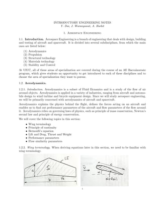
  • 1. INTRODUCTORY ENGINEERING NOTES Y. Dai, J. Waranyuwat, A. Burkit 1. Aerospace Engineering 1.1. Introduction. Aerospace Engineering is a branch of engineering that deals with design, building and testing of aircraft and spacecraft. It is divided into several subdisciplines, from which the main ones are listed below: (1) Aerodynamics (2) Propulsion (3) Structural technology (4) Materials technology (5) Stability and Control At UIUC, all of these areas of specialization are covered during the course of an AE Baccalaureate program, which gives students an opportunity to get introduced to each of these disciplines and to choose the area of specialization they want to pursue. 1.2. Aerodynamics. 1.2.1. Introduction. Aerodynamics is a subset of Fluid Dynamics and is a study of the flow of air around objects. Aerodynamics is applied in a variety of industries, ranging from aircraft and automo- bile design to wind turbine and bicycle equipment design. Since we will study aerospace engineering, we will be primarily concerned with aerodynamics of aircraft and spacecraft. Aerodynamics explains the physics behind the flight, defines the forces acting on an aircraft and enables us to find out performance parameters of the aircraft and flow parameters of the flow around it. Aerodynamics relies on governing laws of physics, such as principle of mass conservation, Newton’s second law and principle of energy conservation. We will cover the following topics in this section: • Wing terminology • Principle of continuity • Bernoulli’s equation • Lift and Drag, Thrust and Weight • Performance parameters • Flow similarity parameters 1.2.2. Wing terminology. When deriving equations later in this section, we need to be familiar with wing terminology. 1
  • 2. In the figure above, a top view of the wing is on the left, and a side view of the wing is on the right. A side view of the wing shows a side cut of the wing, which is called an airfoil. Aerospace engineers utilize the following conventions: b - wingspan S - wing area LE - leading edge, the edge of the wing going in the flow of air first TE - trailing edge, the edge of the wing that the air reaches last c - chord α - angle of attack Question 1.2.1 Aspect ratio is a ratio of the square of the wing span to the wing area, or, AR = b2 S . It is a useful wing parameter that allows to understand the purpose of the aircraft. F-16 fighter jet has wingspan of 32.8 ft and wing area of 300 sq.ft. Boeing Phantom Eye HALE aircraft has 150 ft wingspan and approximately 4 ft chord length. You can assume a rectangular wing. Calculate the aspect ratios of both these aircraft and think about the reasons for why they are different. 1.2.3. Principle of continuity. In aerodynamics, the flow of air is considered a continuum flow since the scale at which aerodynamics studies the forces and stresses around the aircraft is much larger than the scale of a separate air molecule. That is, aerodynamics does not study forces between the molecules, but rather the forces between the air as a whole and the aircraft, particularly its wings. Thus, the air can be considered a continuous mass. Another assumption that is made in aerodynamics to simplify the study of flowing air is a notion of a control volume . The control volume, or V , is an imaginary volume that encloses a finite volume of air and in which the laws of aerodynamics can be applied. Generally, it is assumed that the control volume is fixed in space and the air flows through the control volume. It makes it easier to derive and apply the equations of aerodynamics. The surface of the control volume is called a control surface, and is denoted as S. The principle of continuity is derived from the principle of mass conservation, that states that mass is conserved. That is, the mass that enters the control volume should be the same mass that exits it. In equation form, the principle of continuity looks as follows: (1) ∂ ∂t V ρdV + S ρv · dS = 0 where V is the control volume of interest, S is the surface of this control volume, ρ is the density of air, and v is velocity of the flow through the control surface. The first integral in the equation denotes the rate of change of mass inside the control volume and the second integral is the net amount of mass that flows in and out of the control volume through its surfaces. Equation (1) is called the continuity equation. Note that density, ρ, of the flow can change with time, that is why it is inside the time derivative. If density is not changing with time, the flow is said to be incompressible, otherwise it is compress- ible. Generally, compressible flow occurs at high speeds of air flow. In this section we will assume incompressible flow in order to derive a simplified version of the continuity equation. So, assuming that density is constant, and that the control volume does not change with time, the first integral becomes zero, and that leaves S ρv · dS = 0. Assuming a control volume like in Figure 1, where the air flow cannot exit through upper, lower or side surfaces, we can derive by calculating the dot product between the velocity and the surface area: (2) ρ1A1v1 = ρ2A2v2 where A1 and A2 are respective surfaces of the control volume. Since we assumed that the flow is incompressible, ρ1 = ρ2, and we know that A1 = A2. 2
  • 3. Figure 1. Control volume. Hence, v1 = v2 from equation (2). This means that the speed with which the air enters the control volume as shown in Figure 1, will remain the same when the air exits this control volume. Now define mass flow rate as: (3) ˙m = ρAv where ˙m is the mass flow rate, that is, the change of mass per unit time. Thus, restating equation (2): (4) ˙m1 = ˙m2 Now, if we assume an airfoil in a wind tunnel, as shown in Figure 2, and define a control volume as the volume inside the wind tunnel from inlet 1 to outlet 3, the principle of continuity will still hold, yielding: (5) ˙m1 = ˙m3 (6) ρ1A1v1 = ρ3A3v3 Figure 2. Airfoil in a wind tunnel (schematic). And assuming incompressible flow: (7) A1v1 = A3v3 Since we know that A1 > A3, we conclude that v1 < v3. That is, the speed of the air flow in a narrow section of the wind tunnel is greater than that in a wide section. Question 1.2.2 Consider a convergent duct with an inlet area A1 = 5 m2. Air enters this duct with velocity v1 = 10 m/s and leaves the duct exit with a velocity v2 = 30 m/s. Assuming incompressible flow, what is the area of the duct exit? 3
  • 4. 1.2.4. Bernoulli’s equation. Bernoulli’s equation is derived from Newton’s second law, that states that force = mass × acceleration, or more generally, force is equal to time rate of change of momentum. That is, (8) F = ∂ ∂t (mv) Applying it to a control volume, we obtain: (9) ∂ ∂t V ρvdV + S (ρv · dS)v = − S pdS + V ρfdV + Fviscous where p is the pressure exerted on the surfaces of the control volume, f is the body force on the air inside the control volume, and Fviscous are the forces resulting from friction on the surfaces of control volume. Equation (9) is called the momentum equation in integral form. When expanded to x, y and z coordinates, the previous equation becomes a set of differential equations. This set of equations is called the momentum equation in differential form. We present the equation for only one of the dimensions: x-direction, since the other two are analogous. (10) ∂(ρu) ∂t + · (ρu)v = − ∂p ∂x + ρfx + (Fx)viscous where u is the velocity component in x-direction, and is gradient, or ∂u ∂x + ∂u ∂y + ∂u ∂z , and only ∂u ∂x is non-zero. In our case, we assume an inviscid flow, which makes (Fx)viscous = 0. Moreover, we can assume that the body force is negligibly small compared to pressure forces acting on the surfaces, so we can ignore body forces, that is fx = 0. Also, as before, the flow is incompressible, so ∂(ρu) ∂t becomes zero. Integrating u∂u ∂x and ∂p, and getting a constant from integrating 0 on the right hand side of the equation, we obtain: (11) 1 2 ρu2 + p = const = p0 or more generally, (12) 1 2 ρv2 + pstatic = ptotal Equation (12) is called Bernoulli’s equation, and states that the total pressure at a point in the control volume equals to the sum of static and dynamic pressures, where (13) q = 1/2ρv2 is dynamic pressure. For our control volume, (14) pt1 = ps1 + q1 = ps3 + q3 = pt3 Now, using the previous conclusion that v1 < v3, and knowing from Bernoulli’s equation that pt1 = pt3, we can conclude that when velocity increases at point 3 (i.e. q3 increases), the static pressure ps3 decreases to conserve the total pressure. Thus, the static pressure above the airfoil is less than the static pressure below it, which will induce an upward force, called lift. Question 1.2.3 Consider an airfoil in a flow of air, where far ahead of the airfoil, the pressure, density and velocity are 1.01×10⁵ N/m2, 1.225 kg/m3, and 150 km/h respectively. At a given point A on the airfoil, the pressure is 9.95 ×10⁴ N/m2. What is the velocity at point A? 4
  • 5. 1.2.5. Lift and Drag, Thrust and Weight. Lift is an aerodynamic force that enables the aircraft to fly. Lift results from pressure and stress distribution on the airfoil. The other aerodynamic force that results from pressure distribution on the airfoil is drag. Drag opposes the motion of the aircraft forward. For a well designed airfoil, drag is much less than lift. The force that enables the motion of the aircraft forward is called thrust. It is produced by engines of the aircraft. And the last main force acting on the aircraft is weight. The forces acting on the are summarized in Figure 3 below. Figure 3. Main aerodynamic forces acting on aircraft. 1.2.6. Performance parameters. Lift can be calculated using formula: (15) L = qScL where L - lift force, q - dynamic pressure, S - wing area, and cL - lift coefficient . It is a dimensionless number, and is an important performance parameter in aircraft design. Drag is calculated using a similar formula: (16) D = qScD where D - drag force, cD - drag coefficient, and is also an important dimensionless performance parameter. As mentioned earlier, for a well designed airfoil cL >> cD, that is drag coefficient is usually an order of magnitude less than lift coefficient. Lift and drag coefficients allow us to evaluate the performance of different airfoils without knowing their shapes or sizes. These coefficients are one of the main deliverables in aircraft design reports. Question 1.2.4 For a Boeing 747-200 in cruise flight at an altitude of 40,000 ft with the wing area of 5,500 ft2, the following flight conditions have been reported: air density = 0.00058735 slug/ft3, true airspeed = 871 ft/s, lift coefficient = 0.52, drag coefficient = 0.022. Calculate the lift force on the aircraft. What is the maximum weight at takeoff for Boeing 747-200? What is the required thrust power? 5
  • 6. 1.2.7. Flow similarity parameters. When tests on designing new airfoils are conducted, they take place in wind tunnels, in which the sizes of wing models are much smaller than the full size aircraft wings. What enables aerospace engineers to use the results from wind tunnel tests to predict full size wing performance? The flow similarity parameters. There are many parameters that are reported from wind tunnel tests, but we will focus on two main ones in this section. They are Mach and Reynolds numbers. These numbers are also dimensionless, but can deliver plenty of information about the flow of air around the wing. These numbers are used to mimic the conditions under which the wind tunnel tests were performed. Moreover, they can predict the performance of a full size model based on the tests on the scaled model. Mach number is defined as the ratio of the speed of the air flow to the speed of sound. (17) M = v a where M - Mach number, v - speed of air flow, a - speed of sound at that attitude. The speed of sound varies with altitude, according to a formula: (18) a = γRT where γ - specific heat, (usually equal to 1.4), R - universal gas constant, equal to 287 J/kg/K (1716 ft-lb/slug/oR), T - temperature at the altitude of interest. Depending on Mach number, the flow can be: • Subsonic M < 1 • Transonic 0.8 < M < 1.2 • Supersonic M > 1 • Hypersonic M > 5 Reynolds number is a measure of the viscosity of the flow and is defined as: (19) Re = ρvc µ where Re - Reynolds number, ρ - density of the flow, v - speed of the flow, c - chord length, µ - viscosity of the flow. Reynolds number is usually of the magnitude of 106 for an inviscid flow, and about 104 and lower for a viscous flow. Question 1.2.5 An aircraft flies at speed of 800 km/h at an altitude of 35,000 ft. The temperature of the surroundings is -51oC. What is the Mach number at which the aircraft is flying? Lift and drag coefficients depend on both Mach and Reynolds numbers and also on an angle of attack, i.e. cL = f(M, Re, α) and cD = g(M, Re, α), and the exact expresisons for cL and cD are difficult to obtain. However, during wind tunnel tests, the values of lift and drag forces can be obtained experimentally, and the lift and drag coefficients can be calculated from Equations (15) and (16) respectively. A visual representation of how lift coefficient varies with angle of attack as shown in Figure 4 below: 6
  • 7. Figure 4. Angle of attack vs. lift coefficient It can be seen that lift coefficient increases as the angle of attack increases, however only to some point. That point is called a critical angle of attack, or αstall. After this point, stall occurs, that is no more lift can be generated at that angle of attack. This is a dangerous condition for aircraft flight, that is why there are plenty of instruments onboard the aircraft that warn the pilot of the approaching of the angle of attack that will cause stalling. Question 1.2.6 If the section lift acting on a two-dimensional wing of chord 2 m, flying at 250 km/h in sea level altitude is 3000 N/m, when the angle of attack is 4o and section lift curve slope is 0.11, determine the zero lift angle of attack of the wing. *Note that ρ=1.225 kg/m3 at sea level altitude and lift coefficient varies with angle of attack ac- cording to cL = k ∗ (α − α0), where k - slope of lift curve, α - angle of attack (in degrees), α0 - zero lift angle of attack (in degrees). 7