SlideShare a Scribd company logo
1 of 34
ME 630
1
ANALYSIS AND AUTOMATION OF
SINGLE CYLINDER PISTON ENGINE
ME 630 DESIGN PROJECT
AJINKYA SHEWALE (106617938)
DEEPAK KUMAR SINGH (106667949)
EDWARD KOJAYAN (102140686)
KABILAN PRABHAKAR (106611516)
TEJASHKUMAR PATEL (105919253)
May 14, 2015
ME 630
2
ACKNOWLEDGEMENT
In this opportunity, we would like to express our sincere appreciation to our instructor Dr. Stewart
Prince for the excellence of supervision, unreserved guidance, thought provoking discussion and
continuous encouragement throughout this study. This Design project is all about sincere work,
thoughtful research and strong belief. For this happen I would like to thank all my group members.
Without support from all this project may not be as successful.I appreciate work of each and every person
for this and I am grateful more than they might know.
ME 630
3
ABSTRACT
The accompanying undertaking is automation of single cylinder internal
combustion engine, where the principle parts to be examined are engine block,
crank shaft, connecting rod, piston. This engine parts and assembly are made on
SolidworksTM. The motion study, static and dynamic investigation is done to
decrease the factor of safety alongside changing of connecting rod diameters. The
fundamental objective is to make the methodology at the snap of the mouse and
getting the outcomes just by entering the associating pole measurement qualities
utilizing the control alternatives. We have done the outlining and macros alongside
alternate examinations on SolidworksTM 2014. Changing the diameters, Mass
properties, Part recovery, Static study, loading are finished. We studied how to
design, dissect the loads, computerize and control the Solidworks part report in the
Final task.
ME 630
4
INTRODUCTION
The fundamental point of the task is to outline the connecting rod and
camshaft in such a path, to the point that their primary highlights are effortlessly
controlled, to perform a motion study consider on the assembly to yield force and
motion data, to perform an anxiety recreation think about so as to legitimately
estimate segments in light of a sought variable of security, to perform a design
study to enhance component weight and to mechanize this procedure.
ME 630
5
In our problem, all the dimensional parameters for various components were
already given but for other mechanism analyses; synthesis must be initially
preformed in order to verify the mechanism movement. Once graphical or
modeled synthesis has been performed and we are satisfied with the results of the
mechanism movement, we can now preform analysis. In order to complete
analysis, all the dimensional parameter for the linkages has to be obtained from the
synthesis stage. The following stages will consist of position, velocity and
acceleration. After these three things have been completed, we now preform force
analysis and mass balancing from the equivalent mass equations as seen in the
appendix.
Firstly the assembly is modeled as a four bar slider crank mechanism. As the
crank shaft rotates, the piston reciprocates and the connecting rod connects the two
together, while the connecting rod is actually an assembly of its own. The block
acts as a ground link. It is assumed that the crank shaft rotates at constant angular
velocity while the piston is subjected to gas forces via cylinder pressure due to
combustion and that a constant speed.
To limit the factor of safety and to change the connecting rod parameters we
need to figure Von Misses stresses, Shear stresses, Maximum Principle stress,
motion study, Fatigue Analysis and Optimization in the current Connecting bar. On
the off chance that the current outline demonstrates the higher FOS, then
recommend the base configuration changes in the current Connecting bar. A ton
has been done and still a considerable measure must be done in this field. In this
Project the static and element FEA is finished by Solidworks, shaking strengths
and balancing is finished by Matlab, Automation is finished by exceed expectations
and visual nuts and bolts.
ME 630
6
ASSUMPTIONS
1. Solidworks assembly has been created, consisting of block, crankshaft, piston
wrist pin, head, valves, cam, and connecting rod parts.
2. Piston and head material is 6061 aluminum alloy, crank, valves, valve springs,
wrist pin and connecting rod are 1020 CD steel, block is cast iron.
3. Any part of the engine can be added and altered to make a more “realistic”
engine design.
4. Crankshaft has crank pin diameter “Dia_Cpin.”
5. Starting dimensions are taken directly off of solid models; both stroke and
bore are fixed.
6. All static FOS are 2.5 based on Von Mises.
ME 630
7
DEFINING THE MATERIAL AND MASS PROPERTIES
The cylinder piston material is to be chosen as aluminum, crank and
connecting rod are 1020 CD steel and block is of cast iron. While doing this,
the macro is recorded. Presently the macro scale is altered for the mass
properties and properties of the pole, for example, Description, Part No.,
Material, Cost and Weight. The yield ought to be given as the qualities are
gone into the interface. It is demonstrated macro appended.
DISCUSSION
Design of connecting rod
I. The connecting rod.prt is made utilizing SolidworksTM.
II. The SolidworksTM is opened and another part is chosen from the File
tab.
III. A circle of distance across manager of 3 inch width with balance
separation of dia_cpin of 1.58 inch in front plane.
IV. This manager is Bose expelled with 1.9 inches. From focus purpose of
this manager at 8.5 inch another circle of wrist pin breadth 2 inch is
made with the counterbalance of .787 inch.
V. This wrist pin is bose expelled with 1.9 inch.
VI. After that both the external elements are changed over and the cross
lines are made.
VII. Every other line and external elements are trimmed.
VIII. The Line from supervisor to wrist pin is reflected regarding focus line
and it is expelled with width of 1.7 inch.
IX. Finally the balance is taken as 0.3 inch to evacuate the material and all
the measurements are specified utilizing savvy measurement apparatus.
ME 630
8
Assembly of Engine Block, Connecting Rod, Piston, Crank Shaft
In the new assembly file all the parts are open and must be mate at
each section to rotate the engine properly. The selected mates are
mentioned below which gives the motion of the engine
• Concentric3 (Piston, Engine Block)
The engine block inner curve and piston outer surface are
concentric3 which moves only upward and downward. It will not
move in any other direction
• Distance11 (Crankshaft, Engine Block)
The crank shaft center axis and engine block are fixed with the
distance so they cannot move at any distance.
• Coincident33 (Piston, Engine Block)
The piston front face and engine block’s front face of side are
coincident33 from which the piston moves only for that part.
• Distance12 (Crankshaft, Engine block)
The Engine block’s top edge to the Crankshaft’s axis1 distance is
fixed so it cannot make any changes in motion.
• Parallel20 (Engine Block, Crank Shaft)
The Engine Block’s front face and crank shafts right plane are
parallel so that the engine motion can start at zero degree.
• Concentric4 (Crankshaft, Connecting rod)
The Connecting rods dia_cpin and crankshaft pin are concentric4 so
that they can fix it at one axis place.
• Coincident34 (Crankshaft, Connecting Rod)
The crankshaft’s front plane and Connecting rods front planes are taken
to coincide both the parts.
ME 630
9
• Concentric5 (Piston, Connecting rod)
The piston pin diameter and connecting rods wrist pin are concentric5
to fix two parts on the same axis.
Performance of Motion study at 2000 rpm & Gas pressure
I. To open the motion study tab we have to first go to tools/add ins and
check the box of solidworks Motion and solidworks Simulation.
II. At the end of solidworks screen the motion study tab will popup.
III. By clicking that we will get the new part above that to get the motion.
IV. In this motion study we can get different types of motion with forces,
torque, damper, spring, motor, gravity, contact.
V. After putting this different constrains we can get the animation.
First we have put the motor to the axis of crank shaft at 2000rpm with
the reverse direction and which is for 0.06 second. We have put force on
the top surface of the piston which is 1000lbf in the downward direction.
After that the calculation made for the motion study which gives the
motion analysis option to get the Motion Analysis.
Motion Analysis
In movement investigation we can get the von misses stress, deformity,
factor of safety charts at distinctive part of the part. For that first we need to
choose reenactment setup. In which we have chosen connecting rod as a part
and include the time which is .06 sec. After that the estimation of reproduction
results is done which ascertain the diagrams of the FOS, Stress and
displacement. After computation we are taking the consequences of FOS is
checked.
ME 630
10
Static Study for connecting rod
For static study we need to import the loads in the 360 degree cycle so
we can get for the various frame study. For that following process is carried
out:
I. From the menu bar recreation tab we have chosen import movement
loads.
II. In that the choice of connecting rod is done and the frame is chosen as
well.
III. After that we have open the old connecting rod.
IV. It opens two new tabs which is for single framing and multi frame.
V. In multi frame we need to run the methodology which gives situation
for diverse edge.
VI. It gives the diagram for distinctive situation at anxiety level.
VII. From which we can get the greatest stresses at diverse situation.
VIII. After that we need to open the single edge study tab in which we need
to run and study the outcomes.
IX. This outcome issues us the variable of factor of safety at distinctive
level.
X. From this we can get the most extreme and least FOS of the part.
XI. To limit the factor of safety we need to improve the associating pole.
ME 630
11
OPTIMIZATION
Target of the improvement assignment was to minimize the mass of the
connecting rod under the impact of a load reach containing the two great loads,
the crest compressive gas load, such that the most extreme, least, and the
comparable stress adequacy are inside the cutoff points of the suitable hassles.
The creation expense of the connecting rod was likewise to be minimized.
Besides, the buckling load figure under the top gas burden must be passable.
Mathematically stated, the optimization statement would appear as
follows:
Objective: Minimize Mass
Subject to:
Compressiveload = peak compressivegas load.
Maximum stress < Allowable stress.
Side constraints (Component dimensions).
Manufacturing constraints.
Buckling load > Factorof safety x the maximum gas load (Recommended
FOS, 2-4)
Optimization of connecting rod
To enhance the connecting rod we need to open the new outline study
tab. In design configuration study we need to first choose the distinctive
parameters like measurement of diameter of boss, profundity of con rod,
diameter across of pin. In compel we have taken von misses stress, and our
objective is to decrease the mass.
ME 630
12
Static study of crank shaft
We have to do the same process for the crank shaft to get the static
study. By opening the separate part we have to run the process in the multiple
frames and from the graph we can get the maximum stress value of the crank
shaft. After that open the new single frame in which we are getting the
maximum and minimum Factor of Safety.
ME 630
13
VBA CODING PROCEDURE
I. First exported part material, weight and all the characteristics of
the material to SolidworksTM.
II. In SolidworksTM we did perform the material handling and
exported to Excel.
III. We automated the diameter of Crankpin using Excel VBA.
IV. Then crank pin dia is coordinated with the connecting rod dia so
that in the event that we change the crank pin dia , the dia of
connecting rod changes naturally relating to the crank pin dia.
V. Importing mass properties from solidworks to VBA.
VI. By using MATLAb we did iterations.
VII. We prformed motion analysis and compared it to Matlab output.
VIII. The comparison states it all; we did perfect coding.
ME 630
14
ANALYSIS
Connecting Rod:
I. Connecting rod with constraints:
II. Connecting Rod displacement:
ME 630
15
III. Connecting rod factor safety:
IV. Connecting rod strain:
ME 630
16
V. Connecting rod stress:
Crankshaft:
VI. Crankshaft with constraints:
ME 630
17
VII. Crankshaft with displacement:
VIII. Crankshaft Factor of safety:
ME 630
18
IX. Crankshaft Strain:
X. Crankshaft Stress:
ME 630
19
Piston:
XI. Piston Constraints:
XII. Piston Displacement:
ME 630
20
XIII. Piston Factor of Safety:
XIV. Piston Strain:
ME 630
21
XV. Piston Stress:
ME 630
22
Engine Assembly Views:
ME 630
23
ME 630
24
ME 630
25
GRAPH:
a. Velocity vs Time:
b. Acceleration vs Time :
0.000 0.006 0.012 0.018 0.024 0.030 0.036 0.042 0.048 0.054 0.060
Time (sec)
-151
-76
-1
74
149
0.000 0.006 0.012 0.018 0.024 0.030 0.036 0.042 0.048 0.054 0.060
Time (sec)
-38628
-23425
-8223
6980
22182
Acceleration1(inch/sec**2)
ME 630
26
c. Angular Acceleration vs Time:
0.000 0.006 0.012 0.018 0.024 0.030 0.036 0.042 0.048 0.054 0.060
Time(sec)
44
862
1679
2496
3313
ME 630
27
MOTION STUDY GRAPHS:
FX VS FY:
ME 630
28
FX VS FY:
FX VS FY:
ME 630
29
CONCLUSION
This undertaking is about mechanizing the SolidworksTM assembly plan
utilizing the API. This helps us to know the different systems utilized as a part
of combining VBA coding, Matlab and Designing on a Popular Design
programming. We have the capacity to get the static Factor of Safety as close
to 2.5. These techniques are utilized these days as a part of each programming
interface. We learned the fundamental ideas of making a computerization
code. This can be the eventual fate of outline for 'standard parts' similar to the
Single barrel motor which we made on perceived Design programming like
Solidworks-TM. It's a decent opportunity to take such a class in graduate level
and feel it as a group.
ME 630
30
REFERENCES
Machinery Design book by Robert Norton.
Kinematics of machine By Robert Norton.
Automating SolidworksTMusing Macros, MikeSpens.
Solidworks Library for macros
ME 630 CADMclass by Dr. Stewart Prince.
ME 630
31
APPENDIX
Calculations for Connecting Rod Equivalent Mass:
ME 630
32
ME 630
33
Equivalent mass approach:
𝑚3 = 𝑚3𝐴 + 𝑚3𝐵
𝑚3𝐵 ∙ 𝑙1 = 𝑚3𝐴 ∙ 𝑙2
𝑚3 =
𝑚3𝐵 ∙ 𝑙1
𝑙2
+ 𝑚3𝐵
𝑚3 = 𝑚3𝐵 (
𝑙1
𝑙2
+ 1)
Solving for m3B yields:
𝑚3𝐵 =
𝑚3
(
𝑙1
𝑙2
+ 1)
Crank Equivalent Mass
Equivalent mass approach:
𝑚2 = 𝑚2𝐴 + 𝑚2𝐵
𝑚2𝐵 ∙ 𝑙3 = 𝑚2𝐴 ∙ 𝑙4
𝑚2 =
𝑚2𝐵 ∙ 𝑙3
𝑙4
+ 𝑚2𝐵
𝑚2 = 𝑚2𝐵 (
𝑙3
𝑙4
+ 1)
Solving for m2B yields: 𝑚2𝐵 =
𝑚2
(
𝑙3
𝑙4
+1)
ME 630
34
θ2 (deg) θ2 (rad) θ3 (rad) θ3 (deg) R1 ω3 (rad/s) V1 (in/s) α3 (rad/s^2) A1
Description Value Units 0 0.000 0.000 0.000 3.190 -57.805 0.000 0.000 -21913.154
r2 (Crank Length): 0.69 in 5 0.087 -0.024 -1.378 3.187 -57.602 -16.059 975.638 -21917.707
r3 (Conrod Length): 2.5 in 10 0.175 -0.048 -2.747 3.177 -56.993 -31.923 1948.874 -21929.414
ω2: 2000 RPM 209.4395 rad/s 15 0.262 -0.071 -4.096 3.160 -55.979 -47.400 2917.054 -21942.405
α2: 0 rad/sec^2 20 0.349 -0.095 -5.417 3.137 -54.563 -62.303 3877.021 -21946.899
25 0.436 -0.117 -6.698 3.108 -52.749 -76.456 4824.895 -21929.214
30 0.524 -0.138 -7.932 3.074 -50.544 -89.694 5755.874 -21871.835
35 0.611 -0.159 -9.109 3.034 -47.956 -101.869 6664.089 -21753.573
40 0.698 -0.178 -10.219 2.989 -44.995 -112.848 7542.515 -21549.858
45 0.785 -0.196 -11.254 2.940 -41.676 -122.520 8382.963 -21233.222
50 0.873 -0.213 -12.206 2.887 -38.016 -130.798 9176.164 -20774.015
55 0.960 -0.228 -13.067 2.831 -34.037 -137.617 9911.961 -20141.392
60 1.047 -0.241 -13.829 2.773 -29.765 -142.939 10579.614 -19304.571
65 1.134 -0.253 -14.486 2.712 -25.232 -146.752 11168.204 -18234.360
70 1.222 -0.262 -15.032 2.650 -20.471 -149.071 11667.130 -16904.865
75 1.309 -0.270 -15.462 2.588 -15.523 -149.935 12066.660 -15295.315
80 1.396 -0.275 -15.772 2.526 -10.430 -149.405 12358.490 -13391.834
85 1.484 -0.279 -15.959 2.464 -5.240 -147.565 12536.261 -11189.029
90 1.571 -0.280 -16.022 2.403 0.000 -144.513 12595.972 -8691.221
95 1.658 -0.279 -15.959 2.344 5.240 -140.361 12536.261 -5913.181
100 1.745 -0.275 -15.772 2.286 10.430 -135.230 12358.490 -2880.289
105 1.833 -0.270 -15.462 2.231 15.523 -129.243 12066.660 371.927
110 1.920 -0.262 -15.032 2.178 20.471 -122.525 11667.130 3798.837
115 2.007 -0.253 -14.486 2.129 25.232 -115.195 11168.204 7348.234
120 2.094 -0.241 -13.829 2.083 29.765 -107.366 10579.614 10962.215
125 2.182 -0.228 -13.067 2.040 34.037 -99.140 9911.961 14579.240
130 2.269 -0.213 -12.206 2.000 38.016 -90.609 9176.164 18136.216
135 2.356 -0.196 -11.254 1.964 41.676 -81.852 8382.963 21570.479
140 2.443 -0.178 -10.219 1.932 44.995 -72.935 7542.515 24821.550
145 2.531 -0.159 -9.109 1.903 47.956 -63.910 6664.089 27832.628
150 2.618 -0.138 -7.932 1.879 50.544 -54.819 5755.874 30551.778
155 2.705 -0.117 -6.698 1.858 52.749 -45.692 4824.895 32932.836
160 2.793 -0.095 -5.417 1.840 54.563 -36.550 3877.021 34936.053
165 2.880 -0.071 -4.096 1.827 55.979 -27.406 2917.054 36528.537
170 2.967 -0.048 -2.747 1.818 56.993 -18.266 1948.874 37684.519
175 3.054 -0.024 -1.378 1.812 57.602 -9.131 975.638 38385.518
180 3.142 0.000 0.000 1.810 57.805 0.000 0.000 38620.420
185 3.229 0.024 1.378 1.812 57.602 9.131 -975.638 38385.518
190 3.316 0.048 2.747 1.818 56.993 18.266 -1948.874 37684.519
195 3.403 0.071 4.096 1.827 55.979 27.406 -2917.054 36528.537
200 3.491 0.095 5.417 1.840 54.563 36.550 -3877.021 34936.053
205 3.578 0.117 6.698 1.858 52.749 45.692 -4824.895 32932.836
210 3.665 0.138 7.932 1.879 50.544 54.819 -5755.874 30551.778
215 3.752 0.159 9.109 1.903 47.956 63.910 -6664.089 27832.628
220 3.840 0.178 10.219 1.932 44.995 72.935 -7542.515 24821.550
225 3.927 0.196 11.254 1.964 41.676 81.852 -8382.963 21570.479
230 4.014 0.213 12.206 2.000 38.016 90.609 -9176.164 18136.216
235 4.102 0.228 13.067 2.040 34.037 99.140 -9911.961 14579.240
240 4.189 0.241 13.829 2.083 29.765 107.366 -10579.614 10962.215
245 4.276 0.253 14.486 2.129 25.232 115.195 -11168.204 7348.234
250 4.363 0.262 15.032 2.178 20.471 122.525 -11667.130 3798.837
255 4.451 0.270 15.462 2.231 15.523 129.243 -12066.660 371.927
260 4.538 0.275 15.772 2.286 10.430 135.230 -12358.490 -2880.289
265 4.625 0.279 15.959 2.344 5.240 140.361 -12536.261 -5913.181
270 4.712 0.280 16.022 2.403 0.000 144.513 -12595.972 -8691.221
275 4.800 0.279 15.959 2.464 -5.240 147.565 -12536.261 -11189.029
280 4.887 0.275 15.772 2.526 -10.430 149.405 -12358.490 -13391.834
285 4.974 0.270 15.462 2.588 -15.523 149.935 -12066.660 -15295.315
290 5.061 0.262 15.032 2.650 -20.471 149.071 -11667.130 -16904.865
295 5.149 0.253 14.486 2.712 -25.232 146.752 -11168.204 -18234.360
300 5.236 0.241 13.829 2.773 -29.765 142.939 -10579.614 -19304.571
305 5.323 0.228 13.067 2.831 -34.037 137.617 -9911.961 -20141.392
310 5.411 0.213 12.206 2.887 -38.016 130.798 -9176.164 -20774.015
315 5.498 0.196 11.254 2.940 -41.676 122.520 -8382.963 -21233.222
320 5.585 0.178 10.219 2.989 -44.995 112.848 -7542.515 -21549.858
325 5.672 0.159 9.109 3.034 -47.956 101.869 -6664.089 -21753.573
330 5.760 0.138 7.932 3.074 -50.544 89.694 -5755.874 -21871.835
335 5.847 0.117 6.698 3.108 -52.749 76.456 -4824.895 -21929.214
340 5.934 0.095 5.417 3.137 -54.563 62.303 -3877.021 -21946.899
345 6.021 0.071 4.096 3.160 -55.979 47.400 -2917.054 -21942.405
350 6.109 0.048 2.747 3.177 -56.993 31.923 -1948.874 -21929.414
355 6.196 0.024 1.378 3.187 -57.602 16.059 -975.638 -21917.707
360 6.283 0.000 0.000 3.190 -57.805 0.000 0.000 -21913.154
Input Parameters
Position Analysis Velocity Analysis Acceleration Analysis

More Related Content

What's hot

SAE BAJA Frame Structural optimization
SAE BAJA Frame Structural optimizationSAE BAJA Frame Structural optimization
SAE BAJA Frame Structural optimizationAkshay Murkute
 
Stress analysis on steering knuckle of the automobile steering system
Stress analysis on steering knuckle of the automobile steering systemStress analysis on steering knuckle of the automobile steering system
Stress analysis on steering knuckle of the automobile steering systemeSAT Publishing House
 
inclined car parking lift mechanism system by 070 batch (IOE Pulchowk)
inclined car parking lift mechanism system by 070 batch (IOE Pulchowk)inclined car parking lift mechanism system by 070 batch (IOE Pulchowk)
inclined car parking lift mechanism system by 070 batch (IOE Pulchowk)Dinesh Rawal
 
3 gear trains(2)
3 gear trains(2)3 gear trains(2)
3 gear trains(2)A-S111
 
Design of-gear-box
Design of-gear-boxDesign of-gear-box
Design of-gear-boxmkpq pasha
 
Design of Flat belt, V belt and chain drives
Design of Flat belt, V belt and chain drivesDesign of Flat belt, V belt and chain drives
Design of Flat belt, V belt and chain drivesDr. L K Bhagi
 
ELECTRONIC SYNCHRONOUS SHAFT FOR SWIVEL AXES DRIVEN BY COUPLED SELFLOCKING WO...
ELECTRONIC SYNCHRONOUS SHAFT FOR SWIVEL AXES DRIVEN BY COUPLED SELFLOCKING WO...ELECTRONIC SYNCHRONOUS SHAFT FOR SWIVEL AXES DRIVEN BY COUPLED SELFLOCKING WO...
ELECTRONIC SYNCHRONOUS SHAFT FOR SWIVEL AXES DRIVEN BY COUPLED SELFLOCKING WO...ijmech
 
Design and fabrication of gearbox with inboard braking of an all terrain vehicle
Design and fabrication of gearbox with inboard braking of an all terrain vehicleDesign and fabrication of gearbox with inboard braking of an all terrain vehicle
Design and fabrication of gearbox with inboard braking of an all terrain vehicleabdul mohammad
 
Two speed gear box mini project
Two speed gear box mini projectTwo speed gear box mini project
Two speed gear box mini projectAravind Ganesh
 
presentation on car for SUPRA event
presentation on car for SUPRA eventpresentation on car for SUPRA event
presentation on car for SUPRA eventSandeep Mishra
 
Design & Optimization of Equipment for Insertion of Tube Bundle of Heat Excha...
Design & Optimization of Equipment for Insertion of Tube Bundle of Heat Excha...Design & Optimization of Equipment for Insertion of Tube Bundle of Heat Excha...
Design & Optimization of Equipment for Insertion of Tube Bundle of Heat Excha...IJMER
 
IRJET- Kinematic Design Methodology of Vertical Coil Tong
IRJET- Kinematic Design Methodology of Vertical Coil TongIRJET- Kinematic Design Methodology of Vertical Coil Tong
IRJET- Kinematic Design Methodology of Vertical Coil TongIRJET Journal
 
Design Project - Front-rowing mechanism - MECH 292
Design Project - Front-rowing mechanism - MECH 292Design Project - Front-rowing mechanism - MECH 292
Design Project - Front-rowing mechanism - MECH 292Stasik Nemirovsky
 

What's hot (20)

SAE BAJA Frame Structural optimization
SAE BAJA Frame Structural optimizationSAE BAJA Frame Structural optimization
SAE BAJA Frame Structural optimization
 
Stress analysis on steering knuckle of the automobile steering system
Stress analysis on steering knuckle of the automobile steering systemStress analysis on steering knuckle of the automobile steering system
Stress analysis on steering knuckle of the automobile steering system
 
Ijariie1189
Ijariie1189Ijariie1189
Ijariie1189
 
Alireza
AlirezaAlireza
Alireza
 
Dw36735744
Dw36735744Dw36735744
Dw36735744
 
FinalReport_Group10
FinalReport_Group10FinalReport_Group10
FinalReport_Group10
 
inclined car parking lift mechanism system by 070 batch (IOE Pulchowk)
inclined car parking lift mechanism system by 070 batch (IOE Pulchowk)inclined car parking lift mechanism system by 070 batch (IOE Pulchowk)
inclined car parking lift mechanism system by 070 batch (IOE Pulchowk)
 
3 gear trains(2)
3 gear trains(2)3 gear trains(2)
3 gear trains(2)
 
Design of-gear-box
Design of-gear-boxDesign of-gear-box
Design of-gear-box
 
Design of Flat belt, V belt and chain drives
Design of Flat belt, V belt and chain drivesDesign of Flat belt, V belt and chain drives
Design of Flat belt, V belt and chain drives
 
ELECTRONIC SYNCHRONOUS SHAFT FOR SWIVEL AXES DRIVEN BY COUPLED SELFLOCKING WO...
ELECTRONIC SYNCHRONOUS SHAFT FOR SWIVEL AXES DRIVEN BY COUPLED SELFLOCKING WO...ELECTRONIC SYNCHRONOUS SHAFT FOR SWIVEL AXES DRIVEN BY COUPLED SELFLOCKING WO...
ELECTRONIC SYNCHRONOUS SHAFT FOR SWIVEL AXES DRIVEN BY COUPLED SELFLOCKING WO...
 
Design and fabrication of gearbox with inboard braking of an all terrain vehicle
Design and fabrication of gearbox with inboard braking of an all terrain vehicleDesign and fabrication of gearbox with inboard braking of an all terrain vehicle
Design and fabrication of gearbox with inboard braking of an all terrain vehicle
 
G012224549
G012224549G012224549
G012224549
 
Two speed gear box mini project
Two speed gear box mini projectTwo speed gear box mini project
Two speed gear box mini project
 
presentation on car for SUPRA event
presentation on car for SUPRA eventpresentation on car for SUPRA event
presentation on car for SUPRA event
 
Design & Optimization of Equipment for Insertion of Tube Bundle of Heat Excha...
Design & Optimization of Equipment for Insertion of Tube Bundle of Heat Excha...Design & Optimization of Equipment for Insertion of Tube Bundle of Heat Excha...
Design & Optimization of Equipment for Insertion of Tube Bundle of Heat Excha...
 
IRJET- Kinematic Design Methodology of Vertical Coil Tong
IRJET- Kinematic Design Methodology of Vertical Coil TongIRJET- Kinematic Design Methodology of Vertical Coil Tong
IRJET- Kinematic Design Methodology of Vertical Coil Tong
 
Design Project - Front-rowing mechanism - MECH 292
Design Project - Front-rowing mechanism - MECH 292Design Project - Front-rowing mechanism - MECH 292
Design Project - Front-rowing mechanism - MECH 292
 
E1303072935
E1303072935E1303072935
E1303072935
 
ME 630 Final
ME 630 FinalME 630 Final
ME 630 Final
 

Viewers also liked

STRESS LIFE BASED FATIGUE ANALYSIS ON AUTOMOTIVE CONNECTING ROD
STRESS LIFE BASED FATIGUE ANALYSIS ON AUTOMOTIVE CONNECTING RODSTRESS LIFE BASED FATIGUE ANALYSIS ON AUTOMOTIVE CONNECTING ROD
STRESS LIFE BASED FATIGUE ANALYSIS ON AUTOMOTIVE CONNECTING RODVishnu R
 
Connecting_Rod_Report_Kramer_Suls_Moon (1)
Connecting_Rod_Report_Kramer_Suls_Moon (1)Connecting_Rod_Report_Kramer_Suls_Moon (1)
Connecting_Rod_Report_Kramer_Suls_Moon (1)Jordan Suls
 
DESIGN AND ANALYSIS OF CONNECTING ROD USING ALUMINIUM ALLOY 7068 T6, T6511
DESIGN AND ANALYSIS OF CONNECTING ROD USING ALUMINIUM ALLOY 7068 T6, T6511 DESIGN AND ANALYSIS OF CONNECTING ROD USING ALUMINIUM ALLOY 7068 T6, T6511
DESIGN AND ANALYSIS OF CONNECTING ROD USING ALUMINIUM ALLOY 7068 T6, T6511 IAEME Publication
 
DESIGN AND ANALYSIS OF I.C. ENGINE PISTON AND PISTON-RING USING CATIA AND ANS...
DESIGN AND ANALYSIS OF I.C. ENGINE PISTON AND PISTON-RING USING CATIA AND ANS...DESIGN AND ANALYSIS OF I.C. ENGINE PISTON AND PISTON-RING USING CATIA AND ANS...
DESIGN AND ANALYSIS OF I.C. ENGINE PISTON AND PISTON-RING USING CATIA AND ANS...IAEME Publication
 
Connecting rod
Connecting rodConnecting rod
Connecting rodkarthi d
 
Manufacturing a piston
Manufacturing a pistonManufacturing a piston
Manufacturing a pistonMuhammad Umar
 
manufacturing of connecting rod
manufacturing of connecting rodmanufacturing of connecting rod
manufacturing of connecting rodMuhammad Waseem
 
Design and Construction of a Connecting rod
Design and Construction of a Connecting rodDesign and Construction of a Connecting rod
Design and Construction of a Connecting rodFaisal Niloy
 
Piston manufacturing process
Piston manufacturing process Piston manufacturing process
Piston manufacturing process ROb Vincing
 
4-stroke Diesel Engine
4-stroke Diesel Engine4-stroke Diesel Engine
4-stroke Diesel EngineMridul Rawat
 
connecting-rods
connecting-rodsconnecting-rods
connecting-rodsdilip510
 
Petrolengines
PetrolenginesPetrolengines
Petrolenginesstooty s
 
Internal Combustion Engines - Construction and Working (All you need to know,...
Internal Combustion Engines - Construction and Working (All you need to know,...Internal Combustion Engines - Construction and Working (All you need to know,...
Internal Combustion Engines - Construction and Working (All you need to know,...Mihir Pai
 
ppt on 2 stroke and 4 stroke petrol engine
ppt on 2 stroke and 4 stroke petrol engineppt on 2 stroke and 4 stroke petrol engine
ppt on 2 stroke and 4 stroke petrol engineharshid panchal
 
I.C.ENGINE PPT
I.C.ENGINE PPTI.C.ENGINE PPT
I.C.ENGINE PPT8695
 
Basics of IC engine
Basics of IC engineBasics of IC engine
Basics of IC engineSLA1987
 

Viewers also liked (20)

STRESS LIFE BASED FATIGUE ANALYSIS ON AUTOMOTIVE CONNECTING ROD
STRESS LIFE BASED FATIGUE ANALYSIS ON AUTOMOTIVE CONNECTING RODSTRESS LIFE BASED FATIGUE ANALYSIS ON AUTOMOTIVE CONNECTING ROD
STRESS LIFE BASED FATIGUE ANALYSIS ON AUTOMOTIVE CONNECTING ROD
 
Connecting_Rod_Report_Kramer_Suls_Moon (1)
Connecting_Rod_Report_Kramer_Suls_Moon (1)Connecting_Rod_Report_Kramer_Suls_Moon (1)
Connecting_Rod_Report_Kramer_Suls_Moon (1)
 
K table
K tableK table
K table
 
DESIGN AND ANALYSIS OF CONNECTING ROD USING ALUMINIUM ALLOY 7068 T6, T6511
DESIGN AND ANALYSIS OF CONNECTING ROD USING ALUMINIUM ALLOY 7068 T6, T6511 DESIGN AND ANALYSIS OF CONNECTING ROD USING ALUMINIUM ALLOY 7068 T6, T6511
DESIGN AND ANALYSIS OF CONNECTING ROD USING ALUMINIUM ALLOY 7068 T6, T6511
 
DESIGN AND ANALYSIS OF I.C. ENGINE PISTON AND PISTON-RING USING CATIA AND ANS...
DESIGN AND ANALYSIS OF I.C. ENGINE PISTON AND PISTON-RING USING CATIA AND ANS...DESIGN AND ANALYSIS OF I.C. ENGINE PISTON AND PISTON-RING USING CATIA AND ANS...
DESIGN AND ANALYSIS OF I.C. ENGINE PISTON AND PISTON-RING USING CATIA AND ANS...
 
Analysis of connecting rod in ansys
Analysis of connecting rod in ansysAnalysis of connecting rod in ansys
Analysis of connecting rod in ansys
 
Connecting rod
Connecting rodConnecting rod
Connecting rod
 
IC Engine Piston Design
IC Engine Piston DesignIC Engine Piston Design
IC Engine Piston Design
 
Manufacturing a piston
Manufacturing a pistonManufacturing a piston
Manufacturing a piston
 
manufacturing of connecting rod
manufacturing of connecting rodmanufacturing of connecting rod
manufacturing of connecting rod
 
Design and Construction of a Connecting rod
Design and Construction of a Connecting rodDesign and Construction of a Connecting rod
Design and Construction of a Connecting rod
 
Piston manufacturing process
Piston manufacturing process Piston manufacturing process
Piston manufacturing process
 
4-stroke Diesel Engine
4-stroke Diesel Engine4-stroke Diesel Engine
4-stroke Diesel Engine
 
connecting-rods
connecting-rodsconnecting-rods
connecting-rods
 
Petrolengines
PetrolenginesPetrolengines
Petrolengines
 
IC Engine PPt
IC Engine PPtIC Engine PPt
IC Engine PPt
 
Internal Combustion Engines - Construction and Working (All you need to know,...
Internal Combustion Engines - Construction and Working (All you need to know,...Internal Combustion Engines - Construction and Working (All you need to know,...
Internal Combustion Engines - Construction and Working (All you need to know,...
 
ppt on 2 stroke and 4 stroke petrol engine
ppt on 2 stroke and 4 stroke petrol engineppt on 2 stroke and 4 stroke petrol engine
ppt on 2 stroke and 4 stroke petrol engine
 
I.C.ENGINE PPT
I.C.ENGINE PPTI.C.ENGINE PPT
I.C.ENGINE PPT
 
Basics of IC engine
Basics of IC engineBasics of IC engine
Basics of IC engine
 

Similar to FinalProject_Report_ADEKT

IRJET- Design & Manufacturing of Double Wishbone Suspension and Wheel Ass...
IRJET-  	  Design & Manufacturing of Double Wishbone Suspension and Wheel Ass...IRJET-  	  Design & Manufacturing of Double Wishbone Suspension and Wheel Ass...
IRJET- Design & Manufacturing of Double Wishbone Suspension and Wheel Ass...IRJET Journal
 
Final Robot Report
Final Robot ReportFinal Robot Report
Final Robot ReportYuji Heid
 
Mm203 labmanual
Mm203 labmanualMm203 labmanual
Mm203 labmanualbadri21
 
Rice Transporter Robot Project Report
Rice Transporter Robot Project ReportRice Transporter Robot Project Report
Rice Transporter Robot Project ReportKristopher Brown
 
Semi Perpetual Motion Machine(ppt)
Semi Perpetual Motion Machine(ppt)Semi Perpetual Motion Machine(ppt)
Semi Perpetual Motion Machine(ppt)Harsh Gupta
 
Automobile engineering e book
Automobile engineering e bookAutomobile engineering e book
Automobile engineering e bookVivek Sharma
 
Research and Application of Automobile Steering Knuckle Test Accuracy
Research and Application of Automobile Steering Knuckle Test AccuracyResearch and Application of Automobile Steering Knuckle Test Accuracy
Research and Application of Automobile Steering Knuckle Test AccuracyIJRESJOURNAL
 
Vibration analysis of ci engine using fft analyzer
Vibration analysis of ci engine using fft analyzerVibration analysis of ci engine using fft analyzer
Vibration analysis of ci engine using fft analyzereSAT Journals
 
Vibration analysis of ci engine using fft analyzer
Vibration analysis of ci engine using fft analyzerVibration analysis of ci engine using fft analyzer
Vibration analysis of ci engine using fft analyzerLaukik Raut
 
Crane Gearbox Helical/Planetary train
Crane Gearbox Helical/Planetary trainCrane Gearbox Helical/Planetary train
Crane Gearbox Helical/Planetary trainDouble Gear
 
Review of shaft failure in Coil Car Assembly
Review of shaft failure in Coil Car AssemblyReview of shaft failure in Coil Car Assembly
Review of shaft failure in Coil Car AssemblyIRJET Journal
 
DESIGN, OPTIMIZATION AND FINITE ELEMENT ANALYSIS OF CRANKSHAFT
DESIGN, OPTIMIZATION AND FINITE ELEMENT ANALYSIS OF CRANKSHAFTDESIGN, OPTIMIZATION AND FINITE ELEMENT ANALYSIS OF CRANKSHAFT
DESIGN, OPTIMIZATION AND FINITE ELEMENT ANALYSIS OF CRANKSHAFTijiert bestjournal
 

Similar to FinalProject_Report_ADEKT (20)

B029010016
B029010016B029010016
B029010016
 
IRJET- Design & Manufacturing of Double Wishbone Suspension and Wheel Ass...
IRJET-  	  Design & Manufacturing of Double Wishbone Suspension and Wheel Ass...IRJET-  	  Design & Manufacturing of Double Wishbone Suspension and Wheel Ass...
IRJET- Design & Manufacturing of Double Wishbone Suspension and Wheel Ass...
 
MEMS1029FinalDesign
MEMS1029FinalDesignMEMS1029FinalDesign
MEMS1029FinalDesign
 
Final Robot Report
Final Robot ReportFinal Robot Report
Final Robot Report
 
FORCES AND DEFLECTION OF COIL SPRINGS
FORCES AND DEFLECTION OF COIL SPRINGSFORCES AND DEFLECTION OF COIL SPRINGS
FORCES AND DEFLECTION OF COIL SPRINGS
 
K031202058062
K031202058062K031202058062
K031202058062
 
Mm203 labmanual
Mm203 labmanualMm203 labmanual
Mm203 labmanual
 
Rice Transporter Robot Project Report
Rice Transporter Robot Project ReportRice Transporter Robot Project Report
Rice Transporter Robot Project Report
 
Semi Perpetual Motion Machine(ppt)
Semi Perpetual Motion Machine(ppt)Semi Perpetual Motion Machine(ppt)
Semi Perpetual Motion Machine(ppt)
 
Quick return mechanism
Quick return mechanismQuick return mechanism
Quick return mechanism
 
Automobile engineering e book
Automobile engineering e bookAutomobile engineering e book
Automobile engineering e book
 
Finite Element Analysis of Disk brake assembly.
Finite Element Analysis of Disk brake assembly.Finite Element Analysis of Disk brake assembly.
Finite Element Analysis of Disk brake assembly.
 
Research and Application of Automobile Steering Knuckle Test Accuracy
Research and Application of Automobile Steering Knuckle Test AccuracyResearch and Application of Automobile Steering Knuckle Test Accuracy
Research and Application of Automobile Steering Knuckle Test Accuracy
 
Vibration analysis of ci engine using fft analyzer
Vibration analysis of ci engine using fft analyzerVibration analysis of ci engine using fft analyzer
Vibration analysis of ci engine using fft analyzer
 
Vibration analysis of ci engine using fft analyzer
Vibration analysis of ci engine using fft analyzerVibration analysis of ci engine using fft analyzer
Vibration analysis of ci engine using fft analyzer
 
Crane Gearbox Helical/Planetary train
Crane Gearbox Helical/Planetary trainCrane Gearbox Helical/Planetary train
Crane Gearbox Helical/Planetary train
 
Review of shaft failure in Coil Car Assembly
Review of shaft failure in Coil Car AssemblyReview of shaft failure in Coil Car Assembly
Review of shaft failure in Coil Car Assembly
 
DESIGN, OPTIMIZATION AND FINITE ELEMENT ANALYSIS OF CRANKSHAFT
DESIGN, OPTIMIZATION AND FINITE ELEMENT ANALYSIS OF CRANKSHAFTDESIGN, OPTIMIZATION AND FINITE ELEMENT ANALYSIS OF CRANKSHAFT
DESIGN, OPTIMIZATION AND FINITE ELEMENT ANALYSIS OF CRANKSHAFT
 
Ijmet 06 07_007
Ijmet 06 07_007Ijmet 06 07_007
Ijmet 06 07_007
 
Ijmet 06 07_007
Ijmet 06 07_007Ijmet 06 07_007
Ijmet 06 07_007
 

FinalProject_Report_ADEKT

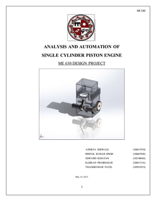
  • 1. ME 630 1 ANALYSIS AND AUTOMATION OF SINGLE CYLINDER PISTON ENGINE ME 630 DESIGN PROJECT AJINKYA SHEWALE (106617938) DEEPAK KUMAR SINGH (106667949) EDWARD KOJAYAN (102140686) KABILAN PRABHAKAR (106611516) TEJASHKUMAR PATEL (105919253) May 14, 2015
  • 2. ME 630 2 ACKNOWLEDGEMENT In this opportunity, we would like to express our sincere appreciation to our instructor Dr. Stewart Prince for the excellence of supervision, unreserved guidance, thought provoking discussion and continuous encouragement throughout this study. This Design project is all about sincere work, thoughtful research and strong belief. For this happen I would like to thank all my group members. Without support from all this project may not be as successful.I appreciate work of each and every person for this and I am grateful more than they might know.
  • 3. ME 630 3 ABSTRACT The accompanying undertaking is automation of single cylinder internal combustion engine, where the principle parts to be examined are engine block, crank shaft, connecting rod, piston. This engine parts and assembly are made on SolidworksTM. The motion study, static and dynamic investigation is done to decrease the factor of safety alongside changing of connecting rod diameters. The fundamental objective is to make the methodology at the snap of the mouse and getting the outcomes just by entering the associating pole measurement qualities utilizing the control alternatives. We have done the outlining and macros alongside alternate examinations on SolidworksTM 2014. Changing the diameters, Mass properties, Part recovery, Static study, loading are finished. We studied how to design, dissect the loads, computerize and control the Solidworks part report in the Final task.
  • 4. ME 630 4 INTRODUCTION The fundamental point of the task is to outline the connecting rod and camshaft in such a path, to the point that their primary highlights are effortlessly controlled, to perform a motion study consider on the assembly to yield force and motion data, to perform an anxiety recreation think about so as to legitimately estimate segments in light of a sought variable of security, to perform a design study to enhance component weight and to mechanize this procedure.
  • 5. ME 630 5 In our problem, all the dimensional parameters for various components were already given but for other mechanism analyses; synthesis must be initially preformed in order to verify the mechanism movement. Once graphical or modeled synthesis has been performed and we are satisfied with the results of the mechanism movement, we can now preform analysis. In order to complete analysis, all the dimensional parameter for the linkages has to be obtained from the synthesis stage. The following stages will consist of position, velocity and acceleration. After these three things have been completed, we now preform force analysis and mass balancing from the equivalent mass equations as seen in the appendix. Firstly the assembly is modeled as a four bar slider crank mechanism. As the crank shaft rotates, the piston reciprocates and the connecting rod connects the two together, while the connecting rod is actually an assembly of its own. The block acts as a ground link. It is assumed that the crank shaft rotates at constant angular velocity while the piston is subjected to gas forces via cylinder pressure due to combustion and that a constant speed. To limit the factor of safety and to change the connecting rod parameters we need to figure Von Misses stresses, Shear stresses, Maximum Principle stress, motion study, Fatigue Analysis and Optimization in the current Connecting bar. On the off chance that the current outline demonstrates the higher FOS, then recommend the base configuration changes in the current Connecting bar. A ton has been done and still a considerable measure must be done in this field. In this Project the static and element FEA is finished by Solidworks, shaking strengths and balancing is finished by Matlab, Automation is finished by exceed expectations and visual nuts and bolts.
  • 6. ME 630 6 ASSUMPTIONS 1. Solidworks assembly has been created, consisting of block, crankshaft, piston wrist pin, head, valves, cam, and connecting rod parts. 2. Piston and head material is 6061 aluminum alloy, crank, valves, valve springs, wrist pin and connecting rod are 1020 CD steel, block is cast iron. 3. Any part of the engine can be added and altered to make a more “realistic” engine design. 4. Crankshaft has crank pin diameter “Dia_Cpin.” 5. Starting dimensions are taken directly off of solid models; both stroke and bore are fixed. 6. All static FOS are 2.5 based on Von Mises.
  • 7. ME 630 7 DEFINING THE MATERIAL AND MASS PROPERTIES The cylinder piston material is to be chosen as aluminum, crank and connecting rod are 1020 CD steel and block is of cast iron. While doing this, the macro is recorded. Presently the macro scale is altered for the mass properties and properties of the pole, for example, Description, Part No., Material, Cost and Weight. The yield ought to be given as the qualities are gone into the interface. It is demonstrated macro appended. DISCUSSION Design of connecting rod I. The connecting rod.prt is made utilizing SolidworksTM. II. The SolidworksTM is opened and another part is chosen from the File tab. III. A circle of distance across manager of 3 inch width with balance separation of dia_cpin of 1.58 inch in front plane. IV. This manager is Bose expelled with 1.9 inches. From focus purpose of this manager at 8.5 inch another circle of wrist pin breadth 2 inch is made with the counterbalance of .787 inch. V. This wrist pin is bose expelled with 1.9 inch. VI. After that both the external elements are changed over and the cross lines are made. VII. Every other line and external elements are trimmed. VIII. The Line from supervisor to wrist pin is reflected regarding focus line and it is expelled with width of 1.7 inch. IX. Finally the balance is taken as 0.3 inch to evacuate the material and all the measurements are specified utilizing savvy measurement apparatus.
  • 8. ME 630 8 Assembly of Engine Block, Connecting Rod, Piston, Crank Shaft In the new assembly file all the parts are open and must be mate at each section to rotate the engine properly. The selected mates are mentioned below which gives the motion of the engine • Concentric3 (Piston, Engine Block) The engine block inner curve and piston outer surface are concentric3 which moves only upward and downward. It will not move in any other direction • Distance11 (Crankshaft, Engine Block) The crank shaft center axis and engine block are fixed with the distance so they cannot move at any distance. • Coincident33 (Piston, Engine Block) The piston front face and engine block’s front face of side are coincident33 from which the piston moves only for that part. • Distance12 (Crankshaft, Engine block) The Engine block’s top edge to the Crankshaft’s axis1 distance is fixed so it cannot make any changes in motion. • Parallel20 (Engine Block, Crank Shaft) The Engine Block’s front face and crank shafts right plane are parallel so that the engine motion can start at zero degree. • Concentric4 (Crankshaft, Connecting rod) The Connecting rods dia_cpin and crankshaft pin are concentric4 so that they can fix it at one axis place. • Coincident34 (Crankshaft, Connecting Rod) The crankshaft’s front plane and Connecting rods front planes are taken to coincide both the parts.
  • 9. ME 630 9 • Concentric5 (Piston, Connecting rod) The piston pin diameter and connecting rods wrist pin are concentric5 to fix two parts on the same axis. Performance of Motion study at 2000 rpm & Gas pressure I. To open the motion study tab we have to first go to tools/add ins and check the box of solidworks Motion and solidworks Simulation. II. At the end of solidworks screen the motion study tab will popup. III. By clicking that we will get the new part above that to get the motion. IV. In this motion study we can get different types of motion with forces, torque, damper, spring, motor, gravity, contact. V. After putting this different constrains we can get the animation. First we have put the motor to the axis of crank shaft at 2000rpm with the reverse direction and which is for 0.06 second. We have put force on the top surface of the piston which is 1000lbf in the downward direction. After that the calculation made for the motion study which gives the motion analysis option to get the Motion Analysis. Motion Analysis In movement investigation we can get the von misses stress, deformity, factor of safety charts at distinctive part of the part. For that first we need to choose reenactment setup. In which we have chosen connecting rod as a part and include the time which is .06 sec. After that the estimation of reproduction results is done which ascertain the diagrams of the FOS, Stress and displacement. After computation we are taking the consequences of FOS is checked.
  • 10. ME 630 10 Static Study for connecting rod For static study we need to import the loads in the 360 degree cycle so we can get for the various frame study. For that following process is carried out: I. From the menu bar recreation tab we have chosen import movement loads. II. In that the choice of connecting rod is done and the frame is chosen as well. III. After that we have open the old connecting rod. IV. It opens two new tabs which is for single framing and multi frame. V. In multi frame we need to run the methodology which gives situation for diverse edge. VI. It gives the diagram for distinctive situation at anxiety level. VII. From which we can get the greatest stresses at diverse situation. VIII. After that we need to open the single edge study tab in which we need to run and study the outcomes. IX. This outcome issues us the variable of factor of safety at distinctive level. X. From this we can get the most extreme and least FOS of the part. XI. To limit the factor of safety we need to improve the associating pole.
  • 11. ME 630 11 OPTIMIZATION Target of the improvement assignment was to minimize the mass of the connecting rod under the impact of a load reach containing the two great loads, the crest compressive gas load, such that the most extreme, least, and the comparable stress adequacy are inside the cutoff points of the suitable hassles. The creation expense of the connecting rod was likewise to be minimized. Besides, the buckling load figure under the top gas burden must be passable. Mathematically stated, the optimization statement would appear as follows: Objective: Minimize Mass Subject to: Compressiveload = peak compressivegas load. Maximum stress < Allowable stress. Side constraints (Component dimensions). Manufacturing constraints. Buckling load > Factorof safety x the maximum gas load (Recommended FOS, 2-4) Optimization of connecting rod To enhance the connecting rod we need to open the new outline study tab. In design configuration study we need to first choose the distinctive parameters like measurement of diameter of boss, profundity of con rod, diameter across of pin. In compel we have taken von misses stress, and our objective is to decrease the mass.
  • 12. ME 630 12 Static study of crank shaft We have to do the same process for the crank shaft to get the static study. By opening the separate part we have to run the process in the multiple frames and from the graph we can get the maximum stress value of the crank shaft. After that open the new single frame in which we are getting the maximum and minimum Factor of Safety.
  • 13. ME 630 13 VBA CODING PROCEDURE I. First exported part material, weight and all the characteristics of the material to SolidworksTM. II. In SolidworksTM we did perform the material handling and exported to Excel. III. We automated the diameter of Crankpin using Excel VBA. IV. Then crank pin dia is coordinated with the connecting rod dia so that in the event that we change the crank pin dia , the dia of connecting rod changes naturally relating to the crank pin dia. V. Importing mass properties from solidworks to VBA. VI. By using MATLAb we did iterations. VII. We prformed motion analysis and compared it to Matlab output. VIII. The comparison states it all; we did perfect coding.
  • 14. ME 630 14 ANALYSIS Connecting Rod: I. Connecting rod with constraints: II. Connecting Rod displacement:
  • 15. ME 630 15 III. Connecting rod factor safety: IV. Connecting rod strain:
  • 16. ME 630 16 V. Connecting rod stress: Crankshaft: VI. Crankshaft with constraints:
  • 17. ME 630 17 VII. Crankshaft with displacement: VIII. Crankshaft Factor of safety:
  • 18. ME 630 18 IX. Crankshaft Strain: X. Crankshaft Stress:
  • 19. ME 630 19 Piston: XI. Piston Constraints: XII. Piston Displacement:
  • 20. ME 630 20 XIII. Piston Factor of Safety: XIV. Piston Strain:
  • 25. ME 630 25 GRAPH: a. Velocity vs Time: b. Acceleration vs Time : 0.000 0.006 0.012 0.018 0.024 0.030 0.036 0.042 0.048 0.054 0.060 Time (sec) -151 -76 -1 74 149 0.000 0.006 0.012 0.018 0.024 0.030 0.036 0.042 0.048 0.054 0.060 Time (sec) -38628 -23425 -8223 6980 22182 Acceleration1(inch/sec**2)
  • 26. ME 630 26 c. Angular Acceleration vs Time: 0.000 0.006 0.012 0.018 0.024 0.030 0.036 0.042 0.048 0.054 0.060 Time(sec) 44 862 1679 2496 3313
  • 27. ME 630 27 MOTION STUDY GRAPHS: FX VS FY:
  • 28. ME 630 28 FX VS FY: FX VS FY:
  • 29. ME 630 29 CONCLUSION This undertaking is about mechanizing the SolidworksTM assembly plan utilizing the API. This helps us to know the different systems utilized as a part of combining VBA coding, Matlab and Designing on a Popular Design programming. We have the capacity to get the static Factor of Safety as close to 2.5. These techniques are utilized these days as a part of each programming interface. We learned the fundamental ideas of making a computerization code. This can be the eventual fate of outline for 'standard parts' similar to the Single barrel motor which we made on perceived Design programming like Solidworks-TM. It's a decent opportunity to take such a class in graduate level and feel it as a group.
  • 30. ME 630 30 REFERENCES Machinery Design book by Robert Norton. Kinematics of machine By Robert Norton. Automating SolidworksTMusing Macros, MikeSpens. Solidworks Library for macros ME 630 CADMclass by Dr. Stewart Prince.
  • 31. ME 630 31 APPENDIX Calculations for Connecting Rod Equivalent Mass:
  • 33. ME 630 33 Equivalent mass approach: 𝑚3 = 𝑚3𝐴 + 𝑚3𝐵 𝑚3𝐵 ∙ 𝑙1 = 𝑚3𝐴 ∙ 𝑙2 𝑚3 = 𝑚3𝐵 ∙ 𝑙1 𝑙2 + 𝑚3𝐵 𝑚3 = 𝑚3𝐵 ( 𝑙1 𝑙2 + 1) Solving for m3B yields: 𝑚3𝐵 = 𝑚3 ( 𝑙1 𝑙2 + 1) Crank Equivalent Mass Equivalent mass approach: 𝑚2 = 𝑚2𝐴 + 𝑚2𝐵 𝑚2𝐵 ∙ 𝑙3 = 𝑚2𝐴 ∙ 𝑙4 𝑚2 = 𝑚2𝐵 ∙ 𝑙3 𝑙4 + 𝑚2𝐵 𝑚2 = 𝑚2𝐵 ( 𝑙3 𝑙4 + 1) Solving for m2B yields: 𝑚2𝐵 = 𝑚2 ( 𝑙3 𝑙4 +1)
  • 34. ME 630 34 θ2 (deg) θ2 (rad) θ3 (rad) θ3 (deg) R1 ω3 (rad/s) V1 (in/s) α3 (rad/s^2) A1 Description Value Units 0 0.000 0.000 0.000 3.190 -57.805 0.000 0.000 -21913.154 r2 (Crank Length): 0.69 in 5 0.087 -0.024 -1.378 3.187 -57.602 -16.059 975.638 -21917.707 r3 (Conrod Length): 2.5 in 10 0.175 -0.048 -2.747 3.177 -56.993 -31.923 1948.874 -21929.414 ω2: 2000 RPM 209.4395 rad/s 15 0.262 -0.071 -4.096 3.160 -55.979 -47.400 2917.054 -21942.405 α2: 0 rad/sec^2 20 0.349 -0.095 -5.417 3.137 -54.563 -62.303 3877.021 -21946.899 25 0.436 -0.117 -6.698 3.108 -52.749 -76.456 4824.895 -21929.214 30 0.524 -0.138 -7.932 3.074 -50.544 -89.694 5755.874 -21871.835 35 0.611 -0.159 -9.109 3.034 -47.956 -101.869 6664.089 -21753.573 40 0.698 -0.178 -10.219 2.989 -44.995 -112.848 7542.515 -21549.858 45 0.785 -0.196 -11.254 2.940 -41.676 -122.520 8382.963 -21233.222 50 0.873 -0.213 -12.206 2.887 -38.016 -130.798 9176.164 -20774.015 55 0.960 -0.228 -13.067 2.831 -34.037 -137.617 9911.961 -20141.392 60 1.047 -0.241 -13.829 2.773 -29.765 -142.939 10579.614 -19304.571 65 1.134 -0.253 -14.486 2.712 -25.232 -146.752 11168.204 -18234.360 70 1.222 -0.262 -15.032 2.650 -20.471 -149.071 11667.130 -16904.865 75 1.309 -0.270 -15.462 2.588 -15.523 -149.935 12066.660 -15295.315 80 1.396 -0.275 -15.772 2.526 -10.430 -149.405 12358.490 -13391.834 85 1.484 -0.279 -15.959 2.464 -5.240 -147.565 12536.261 -11189.029 90 1.571 -0.280 -16.022 2.403 0.000 -144.513 12595.972 -8691.221 95 1.658 -0.279 -15.959 2.344 5.240 -140.361 12536.261 -5913.181 100 1.745 -0.275 -15.772 2.286 10.430 -135.230 12358.490 -2880.289 105 1.833 -0.270 -15.462 2.231 15.523 -129.243 12066.660 371.927 110 1.920 -0.262 -15.032 2.178 20.471 -122.525 11667.130 3798.837 115 2.007 -0.253 -14.486 2.129 25.232 -115.195 11168.204 7348.234 120 2.094 -0.241 -13.829 2.083 29.765 -107.366 10579.614 10962.215 125 2.182 -0.228 -13.067 2.040 34.037 -99.140 9911.961 14579.240 130 2.269 -0.213 -12.206 2.000 38.016 -90.609 9176.164 18136.216 135 2.356 -0.196 -11.254 1.964 41.676 -81.852 8382.963 21570.479 140 2.443 -0.178 -10.219 1.932 44.995 -72.935 7542.515 24821.550 145 2.531 -0.159 -9.109 1.903 47.956 -63.910 6664.089 27832.628 150 2.618 -0.138 -7.932 1.879 50.544 -54.819 5755.874 30551.778 155 2.705 -0.117 -6.698 1.858 52.749 -45.692 4824.895 32932.836 160 2.793 -0.095 -5.417 1.840 54.563 -36.550 3877.021 34936.053 165 2.880 -0.071 -4.096 1.827 55.979 -27.406 2917.054 36528.537 170 2.967 -0.048 -2.747 1.818 56.993 -18.266 1948.874 37684.519 175 3.054 -0.024 -1.378 1.812 57.602 -9.131 975.638 38385.518 180 3.142 0.000 0.000 1.810 57.805 0.000 0.000 38620.420 185 3.229 0.024 1.378 1.812 57.602 9.131 -975.638 38385.518 190 3.316 0.048 2.747 1.818 56.993 18.266 -1948.874 37684.519 195 3.403 0.071 4.096 1.827 55.979 27.406 -2917.054 36528.537 200 3.491 0.095 5.417 1.840 54.563 36.550 -3877.021 34936.053 205 3.578 0.117 6.698 1.858 52.749 45.692 -4824.895 32932.836 210 3.665 0.138 7.932 1.879 50.544 54.819 -5755.874 30551.778 215 3.752 0.159 9.109 1.903 47.956 63.910 -6664.089 27832.628 220 3.840 0.178 10.219 1.932 44.995 72.935 -7542.515 24821.550 225 3.927 0.196 11.254 1.964 41.676 81.852 -8382.963 21570.479 230 4.014 0.213 12.206 2.000 38.016 90.609 -9176.164 18136.216 235 4.102 0.228 13.067 2.040 34.037 99.140 -9911.961 14579.240 240 4.189 0.241 13.829 2.083 29.765 107.366 -10579.614 10962.215 245 4.276 0.253 14.486 2.129 25.232 115.195 -11168.204 7348.234 250 4.363 0.262 15.032 2.178 20.471 122.525 -11667.130 3798.837 255 4.451 0.270 15.462 2.231 15.523 129.243 -12066.660 371.927 260 4.538 0.275 15.772 2.286 10.430 135.230 -12358.490 -2880.289 265 4.625 0.279 15.959 2.344 5.240 140.361 -12536.261 -5913.181 270 4.712 0.280 16.022 2.403 0.000 144.513 -12595.972 -8691.221 275 4.800 0.279 15.959 2.464 -5.240 147.565 -12536.261 -11189.029 280 4.887 0.275 15.772 2.526 -10.430 149.405 -12358.490 -13391.834 285 4.974 0.270 15.462 2.588 -15.523 149.935 -12066.660 -15295.315 290 5.061 0.262 15.032 2.650 -20.471 149.071 -11667.130 -16904.865 295 5.149 0.253 14.486 2.712 -25.232 146.752 -11168.204 -18234.360 300 5.236 0.241 13.829 2.773 -29.765 142.939 -10579.614 -19304.571 305 5.323 0.228 13.067 2.831 -34.037 137.617 -9911.961 -20141.392 310 5.411 0.213 12.206 2.887 -38.016 130.798 -9176.164 -20774.015 315 5.498 0.196 11.254 2.940 -41.676 122.520 -8382.963 -21233.222 320 5.585 0.178 10.219 2.989 -44.995 112.848 -7542.515 -21549.858 325 5.672 0.159 9.109 3.034 -47.956 101.869 -6664.089 -21753.573 330 5.760 0.138 7.932 3.074 -50.544 89.694 -5755.874 -21871.835 335 5.847 0.117 6.698 3.108 -52.749 76.456 -4824.895 -21929.214 340 5.934 0.095 5.417 3.137 -54.563 62.303 -3877.021 -21946.899 345 6.021 0.071 4.096 3.160 -55.979 47.400 -2917.054 -21942.405 350 6.109 0.048 2.747 3.177 -56.993 31.923 -1948.874 -21929.414 355 6.196 0.024 1.378 3.187 -57.602 16.059 -975.638 -21917.707 360 6.283 0.000 0.000 3.190 -57.805 0.000 0.000 -21913.154 Input Parameters Position Analysis Velocity Analysis Acceleration Analysis