Principles of rpd design
•Download as PPT, PDF•
18 likes•9,404 views

Principles of RPD designing

Recommended
More Related Content
What's hot
What's hot (20)
Similar to Principles of rpd design
Similar to Principles of rpd design (20)
More from Abhilash Mohapatra
Recently uploaded
Recently uploaded (20)
Principles of rpd design
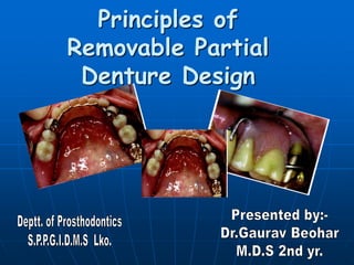
- 1. Principles of Removable Partial Denture Design
- 2. Introduction Removable partial dentures by design are intended to be placed into and removed from the mouth. The forces occurring with removable prosthesis function can be widely distributed and directed, and their effect can be minimized by appropriate design of the removable partial denture
- 3. The strategy of selecting component parts for a partial denture to help control the movement of the prosthesis under functional load has been highlighted as a method to consider for logical partial denture design. The requirements for movement control are generally functions of whether the prosthesis will be tooth supported or tooth-tissue Supported.
- 4. Colonel Arthur H. Schmidt (1953) introduced 5 basic principles in designing of Removable Partial Denture :- 1. Dentist must have a working knowledge of both the mechanical and biological factors included in R.P.D design and construction. 2. Any plan of restoration must be based on complete examination and diagnosis of individual patient. 3. The dentist not the technician should correlate the pertinent factors and recommend a proper plan of treatment. 4. A R.P.D should restore form and function without injury to the tissue. 5. A R.P.D is a form of treatment ,not a care.
- 5. Difference in Prosthesis support All forces against fixed partial denture are directed down long axis of abutment teeth (arrows). Tooth-supported, or Class III, removable partial denture, like fixed partial denture, is supported by abutments. Most forces against it are transmitted down long axis of abutment teeth (arrows). However, limited movement, including a tendency to lift in function, is possible.
- 6. Of all partial dentures, an all-tooth-supported, or Class III, partial denture can best resist forces because it, like the fixed partial denture, is supported by abutment teeth 1 A, Kennedy Class I partially edentulous arch. Major support for denture bases must come from residual ridges, tooth support from occlusal rests being effective only at anterior portion of each base. B, Kennedy Class III, mod 1, partially edentulous arch, which provides total tooth support for prosthesis. Removable partial denture made for this arch is totally supported by rests on properly prepared occlusal rest seats on four abutment teeth. Classes I, II, and IV removable partial dentures are subjected to greater stresses because their support is a combination of tooth and soft tissue
- 7. A removable partial denture in the mouth can perform the action of two simple machines, the lever and the inclined plane If the lever rests against its support and a weight is applied at another point, rotation or movement will occur around the support. The support is known as the fulcrum, and movement takes place around the fulcrum.
- 8. There are three types of levers, first-, second-, and third-class, and each magnifies or disguises the force to a different degree Top, first-class lever. Fulcrum is in center, resistance is at one end, and effort, or force, is at opposite end. This is most efficient and easily controlled lever. Center, second-class lever with fulcrum at one end, effort at opposite end, and resistance in center. This type is seen as indirect retention in removable partial dentures. Bottom, third-class lever with fulcrum at one end, resistance at opposite, and effort in center. This class is not encountered in partial dentures.
- 9. The inclined plane is the other simple machine to be concerned with. Forces against the inclined plane may result in deflection of that which is applying the force or may result in movement to the inclined plane. Neither of these results is desirable. It is in distal extension removable partial dentures that the type of prosthesis controlling stress is important. The all tooth-supported partial denture is rarely subjected to induced stresses, because leverage- type forces are not involved and there are no fulcrums around which the partial denture may rotate. Inclined planes are also not a factor when the partial denture is tooth supported.
- 10. The distal extension partial denture, on the other hand, is subjected to rotation around three principal fulcrums Horizontal fulcrum line passing between two principal abutment teeth controls rotational motion of denture toward or away from supporting ridge. Second rotational fulcrum extends from occlusal rest on terminal abutment posteriorly along crest of residual ridge. This fulcrum controls rocking, or side- to-side, movement that takes place over crest of ridge. In a Class I arch there are two such fulcrums.
- 11. Third fulcrum is vertical and is located in mid-line lingual to anterior teeth. It controls movement of denture in horizontal plane.
- 12. Robert B Potter , Ralph C Appleby, and Cliffton D Adams (1967) : Certain important biomechanical principles apply to the design of all R.P.D, these are :- A modified T bar or I bar engaging the distobuccal retentive area results in action similar to second class lever, when downward pressure is applied to partial denture, the clasp tip will also have downward movement thereby minimizing lateral stress on the abutment tooth. Extra coronal retainers change the contour of abutment teeth. Lingual and palatal major connectors must be rigid to transmit lateral stresses to other parts of the partial denture
- 13. Differentiation between two main types of Removable Partial Denture It is clear that two distinctly different types of removable partial dentures exist. Certain points of difference are present between the Kennedy Class I and Class II types of partial dentures on the one hand and the Class III type of partial denture on the other. 1. The first consideration is the manner in which each is supported. The Class I type and the distal extension side of the Class II type derive their primary support from the tissue underlying the base and secondary support from the abutment teeth The Class III type derives all of its support from the abutment teeth
- 14. 2- Second, for reasons directly related to the manner of support, the method of impression registration and jaw record required for each type will vary. 3- Third, the need for some kind of indirect retention exists in the distal extension type of partial denture, whereas in the tooth-supported, Class III type there is no extension base to lift away from the supporting tissue because of the action of sticky foods and movement of the tissue of the mouth against borders of the denture. 4- Fourth, the manner in which the distal extension type of partial denture is supported often necessitates the use of a base material that can be relined to compensate for tissue changes.
- 15. Differences in Support The distal extension partial denture derives its major support from the residual ridge with its fibrous connective tissue covering. The length and contour of the residual ridge notably influence the amount of available support and stability A, The longer the edentulous area covered by the denture base, the greater the potential lever action on the abutment teeth. B, Flat ridge will provide good support, poor stability. C, Sharp spiny ridge will provide poor support, poor to fair stability. D, Displaceable tissue on ridge will provide poor support and poor stability.
- 16. Impression Registration An impression registration for the fabrication of a partial denture must fulfill the following two requirements: The anatomic form and the relationship of the remaining teeth in the dental arch and the surrounding soft tissue must be recorded accurately so that the denture will not exert pressure on those structures beyond their physiological limits. The elastic impression materials,such as irreversible hydrocolloid (alginate), mercaptan rubber base (Thiokol), silicone impression materials (both condensation and addition reaction), and the polyethers
- 17. The supporting form of the soft tissue underlying the distal extension base of the partial denture should be recorded so that firm areas are used as primary stress-bearing areas and readily displaceable tissues are not overloaded. No single impression material can satisfactorily fulfill both of the previously mentioned requirements. Recording the anatomic form of both teeth and supporting tissue will result in inadequate support for the distal extension base. This is because the cast will not represent the optimum coordinating forms, which necessitates that the ridge be related to the teeth in a supportive form.
- 18. Differences in Clasp Design A fifth point of difference between the two main types of removable partial dentures lies in their requirements for direct retention
- 19. The tooth-supported partial denture, being totally supported by abutment teeth, is retained and stabilized by a clasp at each end of each edentulous space The only requirement of such clasps is that they flex sufficiently during placement and removal of the denture to pass over the height of contour of the teeth in approaching or escaping from an undercut area, Cast retentive arms are generally used for this purpose. These may be either of the circumferential type, arising from the body of the clasp and approaching the undercut from an occlusal direction, or of the bar type, arising from the base of the denture and approaching the undercut area from a gingival direction.
- 20. In the combination tooth- and tissue-supported removable partial dentures, because of this tissue ward movement, those elements of a clasp that lie in an undercut area mesial to the fulcrum for a distal extension (as is often seen with a distal rest) must be able to flex sufficiently to dissipate stresses that otherwise would be transmitted directly to the abutment tooth as leverage
- 21. SURVEY LINES A survey line is a line produced on a cast by a surveyor marking the greatest prominent of contour in relation to the planned path of placement of a restoration. (GPT 7) The survey line marks the height of contour of the tooth. Blatterfein divided the buccal and lingual surfaces in to two halves and described them as the near zone , the area which is closer to the edentulous space and the far zone , the area away from the edentulous space. The proximal surface can also be described in the same manner. Survey lines can be classified as: HIGH SURVEY LINE MEDIUM SURVEY LINE LOW SURVEY LINE DIAGONAL SURVEY LINE
- 22. HIGH SURVEY LINE PASSES FROM THE OCCLUSAL THIRD IN THE NEAR ZONE TO THE OCCLUSAL THIRD IN THE FAR ZONE.UNDERCUT WILL BE DEEP- A WROUGHT WIRE CLASP WHICH IS MORE FLEXIBLE SHOULD BE USED. MEDIUM SURVEY LINE PASSES FROM THE OCCLUSAL THIRD IN THE NEAR ZONE TO THE MIDDLE THIRD IN THE FAR ZONE. AKER’S OR ROACH CLASP IS USED. LOW SURVEY LINE IS CLOSER TO THE CERVICAL THIRD OF THE TOOTH IN BOTH NEAR AND FAR ZONE. A MODIFIED T- CLASP IS USED. DIAGONAL SURVEY LINE RUNS FROM OCCLUSAL THIRD IN THE NEAR ZONE TO CERVICAL THIRD OF FAR ZONE.A REVERSE CIRCLET CLASP IS USED.
- 23. Clasp Design Circumferential Cast Clasp The conventional circumferential cast clasp originating from a distal occlusal rest on the terminal abutment tooth and engaging a mesio buccal retentive undercut should not be used on a distal extension removable partial denture. The terminal of this clasp reacts to movement of the denture base toward the tissue by placing a distal tipping, or torquing, force on the abutment tooth This particular force is the most destructive force a retentive clasp can exert. This clasping concept must be avoided at all costs.
- 24. The reverse circlet, a cast circumferential clasp that approaches a distobuccal undercut from the mesial surface of a terminal abutment tooth, is acceptable The effect on the abutment tooth is reversed from that of the conventional circumferential clasp. As an occlusal load is applied to the denture base, the retentive terminal moves further gingivally into the undercut area and loses contact with the abutment tooth. In this manner torque is not transmitted to the abutment tooth A reverse circlet clasp, approaching a distobuccal undercut from mesial occlusal surface, may be acceptable for a distal extension partial denture. As denture base moves toward the tissue, retentive clasp tip will tend to move into an area of greater undercut (arrow). This action releases torquing forces that can damage an abutment tooth
- 25. Vertical Projection, or Bar, Clasp The vertical projection, or bar, clasp is used on the terminal abutment tooth on a distal extension partial denture when the retentive undercut is located on the distobuccal surface. It is never indicated when the tooth has a mesiobuccal undercut. The bar clasp functions in a manner similar to the reverse circumferential clasp. As the denture base is loaded toward the tissue, the retentive tip of the T clasp rotates gingivally to release the stress being transmitted to the abutment tooth The vertical projection T Clasp releases torsional stress on terminal abutment tooth. This releasing action is accomplished when retentive clasp tip rotates gingivally into a greater undercut as tissueward forces are applied to denture base (arrows). Rotation takes place around distal occlusal rest.
- 26. One school of thought on the philosophy of removable partial denture design has advocated omitting the distal occlusal rest from the terminal abutment in favor of a mesial rest when a bar clasp is used. advantage claimed for moving the occlusal rest more anteriorly is that the lever arm (the distance from the rest to the denture base) is increased, which causes the force directed toward the residual ridge to be more vertical and thus better tolerated by the ridge One advantage claimed for eliminating distal occlusal rest (A) and placing a mesial rest more anteriorly (B) is that lever arm, represented by distance from rest to denture base, is increased. This increase in length makes rotational action caused by up-and-down movement of denture base in function more vertical. A vertical force is better tolerated by ridge than is a horizontal oblique force.
- 27. Combination Clasp When a mesiobuccal undercut exists on an abutment tooth adjacent to a distal extension edentulous ridge, the combination clasp can be employed to reduce the stress transmitted to the abutment tooth. Wrought alloy wire, by virtue of its internal structure, is more flexible than a cast clasp. It can flex in any spatial plane, whereas a cast clasp flexes in the horizontal plane only. The wrought wire retentive arm has a stress-breaking action that can absorb torsional stress in both the vertical and horizontal planes.
- 28. ESSENTIALS OF PARTIAL DENTURE DESIGN To develop the design, it is first necessary to determine how the partial denture is to be supported In an entirely tooth-supported partial denture the potential support an abutment tooth can provide, consideration should be given to: (1) periodontal health (2) crown and root morphologies (3) crown-to-root ratio (4) bone index area (how the tooth has responded to previous stress) (5) location of the tooth in the arch (6) relationship of the tooth to other support units (length of edentulous span) (7) the opposing dentition.
- 29. In a tooth- and tissue-supported partial denture consideration must be given to: (1) the quality of the residual ridge, which includes contour, quality of the supporting bone and quality of the supporting mucosa (2) the extent to which the residual ridge will be covered by the denture base (3) the type and accuracy of the impression registration; (4) the accuracy of the denture base; (5) the design characteristics of the component parts of the partial denture framework (6) the anticipated occlusal load.
- 30. The second step in systematically developing the design for any removable partial denture is to connect the tooth and tissue support units Major connectors must be rigid so that forces applied to any portion of the denture can be effectively distributed to the supporting structures. Minor connectors arising from the major connector make it possible to transfer functional stress to each abutment tooth through its connection to the corresponding rest and also to transfer the effect of the retainers, rests, and stabilizing components to the remainder of the denture and throughout the dental arch
- 31. The third step is to determine how the removable partial denture is to be retained. Retention is accomplished by mechanical retaining elements (clasps), The key to selecting a successful clasp design for any given situation is to choose one that will: (1) avoid direct transmission of tipping or torquing forces to the abutment (2) accommodate the basic principles of clasp design (3) provide retention against reasonable dislodging forces (4) be compatible with undercut location, tissue contour, and esthetic desires of the patient.
- 32. The fourth step is to connect the retention units to the support units. If direct and indirect retainers are to function as designed, each must be rigidly attached to the major connector. The fifth and last step in this systematic approach to design is to outline and join the edentulous area to the already established design components.
- 33. Controlling Stress by Design Considerations Forces of Adhesion and Cohesion To secure the maximum possible retention through the use of the forces of adhesion and cohesion, the denture base should cover the maximum area of available support and must be accurately adapted to the underlying mucosa To enhance quality of retention through adhesion and cohesion, denture base (arrows] must fit edentulous ridge accurately and must cover maximum area of available support
- 34. Frictional Control The partial denture should be designed so that guide planes are created on as many teeth as possible Term guiding plane is defined as two or more parallel, vertical surfaces of abutment teeth, so shaped to direct a prosthesis during placement and removal. . Development of guide planes on proximal surfaces of teeth adjacent to edentulous spaces will increase retention of partial denture by frictional contact. These guide planes may be created in enamel surfaces
- 35. Quadrilateral Configuration The quadrilateral configuration is indicated most often for Class III arches particularly when there is a modification space on the opposite side of the arch. A retentive clasp should be positioned on each abutment tooth adjacent to the edentulous spaces. This results in the denture being confined within the outline of the four clasps, and leverage on the denture is effectively neutralized.
- 36. Tripod Configuration Tripod clasping is used primarily for Class II arches. If there is a modification space on the dentulous side, the teeth anterior and posterior to the space are clasped to bring about the tripod configuration. This design is not as effective as the quadrilateral configuration, but is most effective in neutralizing leverage in the Class II situation.
- 37. Bilateral Configuration most removable partial dentures fall into the bilateral distal extension group, or Class I the single retentive clasp on each side of the arch should be located near the center of the dental arch or denture bearing area. In the bilateral configuration the clasps exert little neutralizing effect on the leverage-induced stresses generated by the denture base.
- 38. MAJOR AND MINOR CONNECTORS Major connectors : The part of the partial removable denture prosthesis that joins the components of one side of the arch to those on the opposite side.(GPT7) Major connectors should be rigid necessary to provide proper distribution of forces to and from the supporting components Minor connectors : The connecting link between the major connector or base of a partial removable denture prosthesis and the other units of the prosthesis such as the clasp assembly , indirect retainers ,occlusal rests or cingulum rests. (GPT 7)
- 39. Major Connector In the mandibular arch the lingual plate major connector that is properly supported by rests can aid in the distribution of functional stresses to the remaining teeth Major connector, in this case anterior lingual plate, can help control functional stresses on remaining teeth. By contacting a number of teeth, major connector reduces amount of force transmitted to each tooth. Major connector must be supported by rests at each end of anterior span In the maxillary arch the use of a broad palatal major connector that contacts several of the remaining natural teeth through lingual plating can distribute stress over a large area
- 40. Minor Connector The most intimate tooth-to-partial denture contact takes place between the minor connector joining the clasp assembly to the major connector and the guiding planes on the abutment tooth surfaces This close metal-to-enamel contact serves two purposes:- 1. First, it offers horizontal stability to the partial denture against lateral forces on the prosthesis. The tooth with its supporting bone helps dissipate these displacing stresses, 2. Second, through the contact of the minor connector and the abutment tooth, the tooth receives stabilization against lateral stresses.
- 41. DIRECT RETAINERS FOR TOOTH- SUPPORTED PARTIAL DENTURES DIRECT RETAINER : is that component of a partial removable dental prosthesis used to retain and prevent dislodgement, consisting of a clasp assemble and precision attachment. (GPT 7) Clasp assembly: The part of the removable dental prosthesis that acts as a direct retainer and or a stabilizer for a prosthesis by partially encompassing or contacting an abutment tooth.(GPT 7) Precision attachment : An interlocking device ,one component of which is fixed to an abutment or abutments and the other is integrated to a removable dental prosthesis in order to stabilize and/or to retain it. (GPT 7) KEY AND KEYWAYS
- 42. functions: A. To retain the prosthesis against reasonable dislodging forces without damage to the abutment teeth and B. To aid in resisting any tendency of the denture to be displaced in a horizontal plane. The prosthesis cannot move tissueward as the rest supports the retentive components of the clasp assembly. There should be no movement away from the tissue and therefore no rotation about a fulcrum because a direct retainer secures the retentive component. Intracoronal (frictional) retainers are ideal for tooth-supported restorations and offer esthetic advantages that are not possible with extracoronal (clasp) retainers. DALBO EXTRACORONAL ATTACHMENT
- 43. The clasp retainer must not impinge on gingival tissue and must not exert excessive torque on the abutment tooth during placement and removal. It must be located the least distance into the tooth undercut for adequate retention, and it must be designed with a minimum of bulk and tooth contact. The bar clasp arm should be used only when the area for retention lies close to the gingival margin of the tooth. With an excessive tissue undercut, re contouring the abutment and using some type of circumferential direct retainer is advisable. Circumferential clasp Occlusal view of bar clasp
- 44. DIRECT RETAINERS FOR DISTAL EXTENSION PARTIAL DENTURES The retainer should retain the prosthesis, and also be able to flex or disengage when the denture base moves tissueward under function. Thus the retainer may act as a stress-breaker. The clasp arm must be freely flexible in any direction, as dictated by the stresses applied. Round, tapered clasp forms offer advantages of greater and more universal flexibility, less tooth contact, and better esthetics.
- 45. Allison. G. James (1955) :- Explained stress breakers which automatically return the saddle to rest position following displacement. Basic principle involved is that portion of appliance directly attached to the abutment teeth, the anterior part of palatal casting shall be rigid, and with minimum motion possible allowed between it and the abutment. The saddles will be attached to this rigid portion by a narrow isthmus in the saddle casting as close as feasible to the midline of the palatal appliance.
- 46. INDIRECT RETAINERS Indirect retainers :are the components of the partial removable dental prosthesis that assists the direct retainers in preventing displacement of the distal extension denture by functioning through lever action on the opposite side of the fulcrum line when the denture base moves away from the tissues in pure rotation around the fulcrum line. (GPT 7) It must be placed as far anterior from the fulcrum line. It must be placed on a rest seat prepared on an abutment tooth that is capable of withstanding the forces placed on it.
- 47. PLACEMENT OF INDIRECT RETAINERS IN A PARTIALLY EDENTULOUS ARCH A C E G B D F H
- 48. Indirect retainer cannot function effectively on an inclined tooth surface, nor on a single weak incisor tooth ,either a canine or premolar tooth should be used for the support of an indirect retainer. Function : A. Restrict movement of a distal extension base away from the basal seat tissue. B. Support for major connectors.
- 49. ADDITIONAL CONSIDERATIONS INFLUENCING DESIGN Use of a Splint Bar for Denture Support when the edentulous span is too large to ensure adequate support from the adjacent teeth, An anterior splint bar may be attached to the adjacent abutment teeth in such a manner that fixed splinting of the abutment teeth results, with a smooth, contoured bar resting lightly on the gingival tissue to support the removable partial denture A, Splint bar attached to double abutments on either side of arch. . B and C, Denture framework designed to fit and be supported by splint bar.
- 50. Lower canines and lateral incisors splinted together with splint bar. Longevity of these teeth is greatly enhanced by splinting, and enhanced stability of the removable partial denture is provided. Tissue surfaces are minimally contacted by rounded form of lower portion of bar. Anterior and posterior slopes of splint bar must be compatible with path of placement of denture.
- 51. Internal Clip Attachment The internal clip attachment differs from the splint bar in that the internal clip attachment provides both support and retention from the connecting bar Canines have been endodontically treated and are splinted together with round, straight connecting bar, slightly elevated from residual ridge. Retaining left molar as abutment will immeasurably contribute to stability of removable partial denture. B, Tissue surface of completed mandibular restoration containing internal clip attachment.
- 52. Overlay Abutment as Support for a Denture Base Every consideration should be directed to preventing the need for a distal extension removable partial denture. In many instances it is possible to salvage the roots and a portion of the crown of a badly broken-down molar through endodontic treatment.
- 53. Use of a Component Partial to Gain Support A component partial is a removable partial denture in which the framework is designed and fabricated in separate parts. The tooth support and tissue supported components are individually fabricated, and the two are joined with a high impact acrylic resin to become a single, rigid functioning unit A, Design of component part removable partial denture. B, Tooth support component individually fabricated and fit to the master cast. C, Tissue support component individually fabricated and fit to the master cast. D, Tooth and tissue support components assembled on cast. E, Components joined with high-impact resin.
- 54. EXAMPLES OF SYSTEMATIC APPROACH TO DESIGN Class III Removable Partial Denture Removable partial denture in maxillary Class III, Mod 1 arch. Design consists of single palatal connecting a single tooth space to a 2-tooth space. The impression for such modification spaces does not require tissues to be captured in a supportive form. A palatal strap major connector is less bulky and for most patients would be more comfortable than a thicker bar design.
- 55. Kennedy Class II Removable Partial Dentures The Kennedy Class II partial denture actually may be a combination of both tissue-supported and tooth supported restorations. The distal extension base must have adequate tissue support, whereas tooth-supported bases elsewhere in the arch may be made to fit the anatomic form of the underlying ridge
- 56. Bibliography Stewart : Clinical Removable Partial Prosthodontics,second edition ,Ishiyaku European American publishers. Carr, McGivney, Brown: McCracken’s Removable Partial Prosthodontics, eleventh edition ,Mosby publishers. Applegate : Essentials of Removable Partial Denture Prosthesis., saunders Company.