
Recommended
More Related Content
What's hot
What's hot (20)
Similar to Aero engine system john
Similar to Aero engine system john (20)
Recently uploaded
Recently uploaded (20)
Aero engine system john
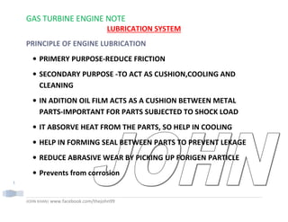
- 1. GAS TURBINE ENGINE NOTE JOHN KHAN| www.facebook.com/thejohn99 1 LUBRICATION SYSTEM PRINCIPLE OF ENGINE LUBRICATION • PRIMERY PURPOSE-REDUCE FRICTION • SECONDARY PURPOSE -TO ACT AS CUSHION,COOLING AND CLEANING • IN ADITION OIL FILM ACTS AS A CUSHION BETWEEN METAL PARTS-IMPORTANT FOR PARTS SUBJECTED TO SHOCK LOAD • IT ABSORVE HEAT FROM THE PARTS, SO HELP IN COOLING • HELP IN FORMING SEAL BETWEEN PARTS TO PREVENT LEKAGE • REDUCE ABRASIVE WEAR BY PICKING UP FORIGEN PARTICLE • Prevents from corrosion
- 2. GAS TURBINE ENGINE NOTE JOHN KHAN| www.facebook.com/thejohn99 2 PROPERTIES OF LUBRICATING OIL VISCOSITY- • MOST IMPORTANT PROPERTIES.THE RESISTANCE OF THE OIL TO FLOW IS KNOWN AS VISCOSITY. • IF FLOW FREELY-LOW VISCOSITY,IF FLOW SLOWELY-HIGH VISCOSITY • VISCOSITY OF OIL IS AFFECTED BY TEMP.VISCOSITY SHOULD BE CHANGE MINIMUM WITH CHANGE IN TEMPERATURE. • OIL SELECTED FOR ENGINE MUST BE LIGHT ENOUGH TO CIRCULATE FREELY,YET HEAVY ENOUGH TO PROVIDE PROPER OIL FILM AT ENGINE OPERATING TEMP. • OIL USED IN PISTION ENGINE SHOULD BE OF HIGH VISCOSITY
- 3. GAS TURBINE ENGINE NOTE JOHN KHAN| www.facebook.com/thejohn99 3 BECAUSE OF LARGE OPERATING CLEARANCE, HIGH OPERATING TEMP,HIGH BEARING PRESSURE. • AN SAE (SOCIETY OF AUTOMOTIVE ENGINEER) RATING FOR PETROLIUM BASED OIL IS DETERMNED BY HEATING 60ML (CC)OF OIL TO ONE SPECIFIC TEMP AND MEASURING THE FLOW TIME AS THE OIL IS POURED THROUGH A CALIBRATED ORIFICE.ONE SUCH DEVICE FOR CALCULATING THIS IS SAYBOLT -UNIVERSAL SECOND(S.U.S) VISCOSIMETER. • LETTER W OCCASIONALY INCLUDED IN THE SAE NUMBER.THIS INDICATES OIL IS ALSO SUITABLE FOR USE IN WINTER...SUCH AS SAE 20W • SAE NO ONLY INDICATE GRADE OF OIL.IT DON'T SHOW OIL QUALITIES. • SYNTHETIC OIL DO NOT HAVE SAE RATING.IT HAS A KINAMATIC
- 4. GAS TURBINE ENGINE NOTE JOHN KHAN| www.facebook.com/thejohn99 4 VISCOSITY RATING IN CENTISTROKE. VISCOSITY INDEX- • IT SHOULD BE HIGH.IT IS AN INDICATION OF HOW WELL THE OIL WILL TENDS TO RETAIN ITS VISCOSITY WHEN HEATED TO ITS OPERATING TEMPERATURE. LOW VOLATILITY- • EASE WITH WHICH LIQUID IS CONVERTED TO VAPOUR STATE.VOLATILITY SHOULD BE LOW TO MINIMIZE EVAPORATION AT HIGH ALTITUDE ANTI FOAMING QUALITY- • OIL FOAMING IS THE MEASURE OF THE RESISTANCE OF THE OIL TO SEPARATE FROM ENTRAINED AIR.FOAMING SHOULD BE LOW FOR MORE POSITIVE LUBRICATION.
- 5. GAS TURBINE ENGINE NOTE JOHN KHAN| www.facebook.com/thejohn99 5 LOW LACQUER AND COKE DIPOSITE- • KEEP SOLID PARTICLE FORMATION TO MINIMUM FILM STRENGTH- • EXCLLENT QUALITY OF COHESION AND ADHESION,A CHARACTERISTICS OF OIL MOLECULES ALLOWING THEM TO STICK TOGETHER UNDER COMPRESSION LOAD AND STICK TO SURFACE UNDER CENTRIFUGAL LOAD WIDE TEMPERATURE RANGE- • APP.-60 DEGREE F TO +400 DEG F. SPECIFIC GRAVITY- • IS ACOMPARISON OF THE WT. OF THE SUBSTANCE TO THE WT. OF
- 6. GAS TURBINE ENGINE NOTE JOHN KHAN| www.facebook.com/thejohn99 6 AN EQUAL VOLUME OF DISTILLED WATER AT SPECIFIED TEMP. HIGH FLASH POINT- • THE TEMP AT WHICH LIQUID WILL BEGIN TO GIVE OFF INGNITABLE VAPOURS(FLASH). HIGH FIRE POINT- • THE TEMP AT WHICH THERE ARE SUFFICIENT VAPOURS TO SUPPORT THE FLAME(FIRE) CLOUD POINT-low • THE TEMP AT WHICH IT WAX CONTAINED ,NORAMALLY HELD IN SOLN, BEGINES TO SOLIDIFY AND SEPARATE INTO TINY CRYSTALS,CAUSING OIL TO APPEAR CLOUDY OR HAZY.CLOUD POINT TEMP IS SLIGHTLY ABOVE SOLIDIFICATION POINT.
- 7. GAS TURBINE ENGINE NOTE JOHN KHAN| www.facebook.com/thejohn99 7 POUR POINT- • THE LOWEST TEMP AT WHICH OIL FLOW OR CAN BE POURED. OILINESS- • DIFFERENCE IN REDUCING FRICTION WHEN OIL HAVING SAME VISCOSITY BUT DIFFERENT OILINESSS ARE COMPARED UNDER THE SAME CONDITION OF TEMP AND PRESSURE.IT IS THE WETTING AFFECT THAT REDUCE FRICTION, DRAG AND WEAR. ACIDITY • IT IS THE CORROSIVE TENDENCY OF THE OIL CORROSION RESISTANCE- • OIL SHOULD BE OF CORROSION RESISTANCE NATURE,NON CORROSIVE TO METAL.
- 8. GAS TURBINE ENGINE NOTE JOHN KHAN| www.facebook.com/thejohn99 8 CHEMICAL AND PHYSICAL STABILITY- • SHOULD HAVE CHAMICAL STABILITY AGAINST OXIDATION,THERMAL CRACKING AND COKING AND IT MUST HAVE PHYSICAL STABILITY WITH REGARDS TO PR AND TEMP. TYPES OF OIL ANIMAL BASE-THIS TYPE OF OIL IS HIGHELY STABLE AT NORMAL TEMPERATURE.USED IN FIREARMS,SEWING MACHINE,CLOCK AND OTHER LIGHT MACHINE.CANNOT BE USED FOR ENGINE BECAUSE IT PRODUCE FATTY ACID AT HIGH TEMP. EX-TALLOW OIL,LARD OIL,NEAT'S FOOT OIL,SPERM OIL VEGITABLE BASE-(MIL-H-7644) COMPOSED OF CASTER OIL AND ALCOHOL.IT HAS PUNGENT ALCOHOLIC ODOR AND IS GENERALLY DYED BLUE.USED IN OLDER AIRCRAFT.NATURAL RUBBER SEAL IS USED
- 9. GAS TURBINE ENGINE NOTE JOHN KHAN| www.facebook.com/thejohn99 9 WITH IT.FLAMMABLE IN NATURE. MINIRAL BASE(MIL-H-5606)PROCESSED FROM PETROLEUM.ODOR SIMILAR TO PENETRATING OIL AND DYED RED.SYNTHETIC RUBBER IS SUITABLE WITH MINIRAL OIL.FLAMMABLE IN NATURE • SOLID TYPE-MICA,SOAPSTONE AND GRAPHITE.DO NOT DISSIPATE HEAR RAPIDELY ENOUGH FOR HIGH SPEED MACHINE.USED IN POWDER FORM. • SEMI-SOLID TYPE-GREASE IS EXAMPLE OF THIS TYPE OF LUBRICANTS.IT IS A MIXTURE OF OIL AND SOAP. • LIQUIED OR FLUID TYPE-USED IN INTERNAL COMBUSTION ENGINE SYNTHATIC BASE OR PHOSPHATE ESTER BASE(SKYDROL) FIRE RESISTANCE IN NATURE MEANS IT DOES NOT SUPPORT COMBUSTION AND RETAIN THEIR CHARECTARISTICS AT HIGH TEMP.
- 10. GAS TURBINE ENGINE NOTE JOHN KHAN| www.facebook.com/thejohn99 10 THAT CAUSE PETROLEUM OIL TO EVAPORATE AND BREAK DOWN INTO HEAVY HYDROCARBON. HYGROSCOPIC IN NATURE. 1.TYPE I,ALKYL DIESTER OIL(MIL-L-7808) 2.TYPE II,POLYSTER OIL(MIL-L-23699) 3.TYPE III LUBRICATING SYSTEMS: THE LUBRICATION SYSTEM SUPPLIES OIL TO THE VARIOUS MOVING PARTS WITHIN THE ENGINE WHICH ARE SUBJECTED TO FRICTION LOADS AND HEATING FROM THE GAS PATH.
- 11. GAS TURBINE ENGINE NOTE JOHN KHAN| www.facebook.com/thejohn99 11 THE OIL IS SUPPLIED UNDER PRESSURE ALONG THE MAIN ROTOR SHAFT AND TO THE GEARBOXES TO REDUCE FRICTION, TO COOL, AND TO CLEAN. IT IS THEN RETURNED BY A SCAVENGING SYSTEM TO THE OIL STORAGE TANK TO BE USED AGAIN AND AGAIN. OIL CONSUMPTION IS LOW IN GAS TURBINE ENGINES AS COMPARED TO PISTON ENGINES, THEY CAN BE AS SMALL AS 3 TO 5 QUART CAPACITY ON BUSINESS JET SIZE ENGINES AND 20 TO 30 QUARTS ON LARGE COMMERCIAL TYPE ENGINES. TYPES OF LUBRICATION SYSTEM WET-SUMP LUBRICATION SYSTEM AN AIRCRAFT ENGINE THAT CARRIES ITS SUPPLY OF LUBRICATING OIL IN A SUMP, OR COMPARTMENT, WHICH IS PART OF THE ENGINE
- 12. GAS TURBINE ENGINE NOTE JOHN KHAN| www.facebook.com/thejohn99 12 ITSELF. AFTER SERVING ITS LUBRICATING FUNCTIONS, THE OIL DRAINS BACK INTO THE SUMP BY GRAVITY. THE WET SUMP SYSTEM IS THE OLDEST DESIGN, AND IT IS STILL SEEN IN AUXILIARY POWER UNITS AND GROUND POWER UNITS BUT RARELY SEEN IN MODERN FLIGHT ENGINES. COMPONENTS OF A WET SUMP SYSTEM ARE SIMILAR TO A DRY SUMP SYSTEM, EXCEPT FOR THE LOCATION OF THE OIL SUPPLY.
- 13. GAS TURBINE ENGINE NOTE JOHN KHAN| www.facebook.com/thejohn99 13 FIGURE SHOWS AN ENGINE WITH A WET SUMP LUBRICATION SYSTEM AND THE OIL CONTAINED IN ITS ACCESSORY GEARBOX. THE BEARINGS AND DRIVE GEARS WITHIN THE SUMP ARE LUBRICATED BY A SPLASH SYSTEM. THE REMAINING POINTS OF LUBRICATION RECEIVE OIL FROM A GEAR TYPE PRESSURE PUMP, WHICH DIRECTS OIL TO OIL JETS AT VARIOUS LOCATIONS IN THE ENGINE.
- 14. GAS TURBINE ENGINE NOTE JOHN KHAN| www.facebook.com/thejohn99 14 MOST WET SUMP ENGINES DO NOT INCORPORATE A PRESSURE RELIEF VALVE AND ARE KNOWN AS VARIABLE PRESSURE SYSTEMS. WITH THIS SYSTEM THE PUMP OUTPUT PRESSURE DEPENDS DIRECTLY ON ENGINE REVOLUTIONS PER MINUTE. SCAVENGED OIL IS RETURNED TO THE SUMP BY A COMBINATION OF GRAVITY FLOW FROM THE BEARINGS AND ALSO SUCTION CREATED BY A GEAR TYPE SCAVENGE PUMP LOCATED WITHIN THE PUMP HOUSING. THE VENT LINE IS PRESENT TO PREVENT OVER PRESSURIZATION OF THE GEARBOX. GAS PATH AIR SEEPING PAST MAIN BEARING SEALS FINDS ITS WAY TO THE GEARBOX VIA THE SCAVENGE SYSTEM AND THE VENT LINE RETURNS THIS AIR TO THE ATMOSPHERE. DRY-SUMP SYSTEM (ENGINE LUBRICATION SYSTEM)
- 15. GAS TURBINE ENGINE NOTE JOHN KHAN| www.facebook.com/thejohn99 15 THE OIL IS HELD IN AN EXTERNAL TANK, DRAWN FROM THE TANK AND CIRCULATED THROUGH THE ENGINE BY AN ENGINE-DRIVEN PRESSURE PUMP. AFTER LUBRICATING THE ENGINE, THE OIL DRAINS INTO A INTEGRAL SUMP FROM WHICH IT IS PICKED UP AND RETURNED TO THE OIL TANK BY A SCAVENGER PUMP.MOST GAS TURBINE ENGINES UTILIZE A DRY SUMP LUBRICATION SYSTEM CONSISTING OF PRESSURE, SCAVENGE, AND BREATHER VENT SUBSYSTEMS.
- 16. GAS TURBINE ENGINE NOTE JOHN KHAN| www.facebook.com/thejohn99 16 THE MAIN OIL SUPPLY IS CARRIED IN A TANK MOUNTED EITHER INTEGRALLY WITHIN THE ENGINE OR EXTERNALLY ON THE ENGINE OR IN THE AIRCRAFT. A SMALLER SUPPLY IS CONTAINED IN A GEARBOX SUMP WHICH ALSO HOUSES THE OIL PRESSURE PUMP. OIL SCAVENGES PUMP, OIL FILTER, AND OTHER LUBE SYSTEMS COMPONENTS. ANOTHER SMALL AMOUNT OF ILL IS RESIDUAL WITHIN THE OIL SYSTEM LINES, SUMPS AND COMPONENTS. HOT-TANK LUBRICATION SYSTEM A LUBRICATION SYSTEM OF A GAS TURBINE ENGINE IN WHICH THE OIL COOLER IS IN THE PRESSURE PORTION OF THE SYSTEM. HOT OIL RETURNS DIRECTLY FROM THE ENGINE INTO THE TANK WITHOUT BEING COOLED. AN ADVANTAGE OF THIS IS THAT A MAXIMUM HEAT EXCHANGE OCCURS BECAUSE OIL HAS LESS ENTRAINED AIR IN THE PRESSURE SIDE OF THE LUBRICATION SYSTEM. THIS FACTOR ALLOWS
- 17. GAS TURBINE ENGINE NOTE JOHN KHAN| www.facebook.com/thejohn99 17 FOR SMALLER OIL COOLER TO BE USED, AND A WEIGHT SAVINGS OCCURS. COLD-TANK LUBRICATION SYSTEM IN THE COLD TANK SYSTEM THE OIL COOLER IS LOCATED IN THE SCAVENGE SUBSYSTEM, WHICH ALLOWS THE OIL TO RETURN TO THE SUPPLY TANK IN A COOLED CONDITION. THE OIL IS STILL AERATED FROM THE ACTION OF ROTATING PARTS WITHIN THE ENGINE AND A REDUCED HEAT EXCHANGE IS SAID TO OCCUR. THIS IS TURN CREATES NEED FOR THE USE OF A HIGH VOLUME OIL COOLER. ALSO, SOME ENGINES HAVE NORMALLY HIGHER OIL TEMPERATURES THAN OTHER. THIS HIGH OIL TEMPERATURE IN THE OIL TANK CAN AFFECT OIL SERVICE LIFE, SINCE THE BULK OIL STORAGE
- 18. GAS TURBINE ENGINE NOTE JOHN KHAN| www.facebook.com/thejohn99 18 IS AT A HIGHER TEMPERATURE FOR A LONGER TIME. IF THIS IS THE CASE, A COLD TANK SYSTEM WILL MOST LIKELY TO BE USED. OIL – SYSTEM COMPONENTS: THE OIL-SYSTEM COMPONENTS USED ON GAS TURBINE ENGINES ARE AS FOLLOWS: • TANK(S) • PRESSURE PUMP(S) • SCAVENGER PUMPS • FILTERS • OIL COOLERS • RELIEF VALVES
- 19. GAS TURBINE ENGINE NOTE JOHN KHAN| www.facebook.com/thejohn99 19 • BREATHERS AND PRESSURIZING COMPONENTS • PRESSURE AND TEMPERATURE GAGES • TEMPERATURE REGULATING VALVES • OIL JET NOZZLES • FITTINGS, VALVES AND PLUMBING • SEALS. OIL TANK: THE OIL SUPPLY RESERVOIR IS USUALLY CONSTRUCTED OF SHEET ALUMINUM OR STAINLESS STEEL AND IS DESIGNED TO FURNISH A CONSTANT SUPPLY OF OIL TO THE ENGINE DURING ALL AUTHORIZED FLIGHT ATTITUDES. IN MOST TANKS, A PRESSURE BUILD- UP IS DESIRED TO ASSURE A POSITIVE FLOW OF OIL TO THE OIL PUMP INLET AND TO SUPPRESS FOAMING IN THE TANK WHICH IN TURN PREVENTS PUMP
- 20. GAS TURBINE ENGINE NOTE JOHN KHAN| www.facebook.com/thejohn99 20 CAVITATIONS. THE BUILDUP IS ACCOMPLISHED BY RUNNING THE TANK OVERBOARD VENT LINE THROUGH A RELIEF VALVE TO MAINTAIN A POSITIVE PRESSURE OF APPROXIMATELY THREE TO SIX POUNDS PER SQUARE INCH GAUGE (PSIG). THAT IS, THE TANK VENT RELIEF VALVE WILL RELEASE EXCESS AIR AT A PRESSURE DIFFERENTIAL OF THREE TO SIX POUNDS PER SQUARE INCH- DIFFERENTIAL (PSID) BETWEEN THE TANK AND AMBIENT OR TANK AND VENT SUB-SYSTEM. AFTER SHUT DOWN A SMALL BLEED ORIFICE IN THE RELIEF VALVE ALLOWS FOR DEPRESSURIZATION OF THE TANK.
- 21. GAS TURBINE ENGINE NOTE JOHN KHAN| www.facebook.com/thejohn99 21 SOME DRY SUMP OIL TANKS ARE THE INTEGRAL TYPE. WHILE THE EXTERNAL SHEET METAL TYPE IS A SEPARATE ASSEMBLY LOCATED OUTSIDE THE ENGINE, THE INTEGRAL OIL TANK IS FORMED BY SPACE
- 22. GAS TURBINE ENGINE NOTE JOHN KHAN| www.facebook.com/thejohn99 22 PROVIDED WITHIN THE ENGINE. IT CAN BE A PROPELLER REDUCTION GEARBOX THAT HOUSES THE OIL OR SOMETIMES A CAVITY BETWEEN MAJOR ENGINE CASES. THE DISTINCTION BETWEEN THE WET SUMP AND DRY SUMP IS THAT THE WET SUMP IS LOCATED IN THE MAIN GEAR BOX AT THE LOWEST POINT WITHIN THE ENGINE, FACILITATING SPLASH LUBRICATION. THE DRY SUMP IS SELDOM LOCATED AT THE LOW POINT ON THE ENGINE. IT MAY OR MAY NOT GRAVITY FLOW OIL TO THE MAIN OIL PUMP INLET. TODAY, SOME OIL TANKS ARE CONFIGURED WITH A REMOTE PRESSURE FILL CAPACITY. AN OIL PUMPING CART CAN BE ATTACHED TO THE TANK AND THE OIL HAND PUMPED INTO THE TANK UNTIL IT IS AT THE PROPER LEVEL, AT WHICH TIME OIL STARTS TO FLOW FROM THE
- 23. GAS TURBINE ENGINE NOTE JOHN KHAN| www.facebook.com/thejohn99 23 OVERFLOW. THE OIL FILLER CAP IS USUALLY REMOVED DURING THIS OPERATION TO PREVENT OVER-SERVICING IN CASE THE OIL OVERFLOW IS NOT PROPERLY CONNECTED. THE HAND GRAVITY OIL TANK FILLING METHOD IS, HOWEVER, STILL THE MOST COMMON. THE SCUPPER SHOWN ON THE ILLUSTRATION IS PRESENT TO CATCH OIL THAT IS SPILLED DURING SERVICING OR DURING CAP BLOW OFF AND TO ROUTE THIS SPILLAGE THROUGH A DRAIN POINT LOCATION AT THE BOTTOM OF THE ENGINE. DUE TO THE POSITION OF THE FILLER CAP, IT IS NOT POSSIBLE TO OVER SERVICE BY THE HAND GRAVITY METHOD. MANY OF THE NEW FILLER OPENINGS ARE FITTED WITH A FLAPPER SEAL, IN THE EVENT THE OIL FILLER CAN IS INADVERTENTLY LEFT OFF. IN PLACE OF A DIPSTICK, SOME OIL TANKS INCORPORATE A SIGHT GAUGE TO SATISFY THE REQUIREMENT FOR A VISUAL MEANS OF CHECKING OIL LEVEL. HOWEVER, THESE GLASS INDICATORS TEND TO CLOUD OVER AFTER PROLONGED USE AND MANY OPERATORS HAVE
- 24. GAS TURBINE ENGINE NOTE JOHN KHAN| www.facebook.com/thejohn99 24 GONE BACK TO THE DIPSTICK. PRESSURE PUMPS: THE FUNCTION OF THE OIL PRESSURE PUMP IS TO SUPPLY OIL UNDER PRESSURE TO THE PARTS OF THE ENGINE THAT REQUIRE LUBRICATION. MANY OIL PUMPS CONSIST OF NOT ONLY OF A PRESSURE LUBE ELEMENT BUT ONE OR MORE SCAVENGE ELEMENTS AS WELL ALL IN ONE HOUSING.BOTH THE GEAR AND GEROTOR TYPE PUMPS ARE USES IN THE LUBRICATING SYSTEM OF THE TURBINE ENGINE. SCAVENGER PUMPS: SCAVENGER PUMPS ARE SIMILAR TO THE PRESSURE PUMPS BUT ARE OF MUCH LARGER TOTAL CAPACITY. AN ENGINE IS GENERALLY PROVIDED WITH SEVERAL SCAVENGER PUMPS TO DRAIN OIL FROM VARIOUS PARTS OF THE ENGINE. OFTEN ONE OR MORE OF THE SCAVENGER ELEMENTS ARE INCORPORATED IN THE SAME HOUSING AS
- 25. GAS TURBINE ENGINE NOTE JOHN KHAN| www.facebook.com/thejohn99 25 THE PRESSURE PUMP. DIFFERENT CAPACITIES CAN BE PROVIDED FOR EACH SYSTEM, DESPITE THE COMMON DRIVING SHAFT SPEED, BY VARYING THE DIAMETER OR THICKNESS OF THE GEARS TO VARY THE VOLUME OF THE TOOTH CHAMBER. A VANE-TYPE PUMP MAY SOMETIMES BE USED. THE THREE MOST COMMON OIL PUMPS ARE: • GEAR TYPES. • GEROTOR TYPE • THE VANE TYPE, ALL ARE CLASSED AS POSITIVE DISPLACEMENT PUMPS BECAUSE THEY DEPOSIT A FIXED QUANTITY OF OIL IN THE PUMP OUTLET PER REVOLUTION. THESE CATEGORY PUMPS ARE ALSO REFERRED TO AS CONSTANT DISPLACEMENT TYPES BECAUSE THEY DISPLACE A
- 26. GAS TURBINE ENGINE NOTE JOHN KHAN| www.facebook.com/thejohn99 26 CONSTANT VOLUME PER REVOLUTION. • GEAR PUMP THE GEAR TYPE PUMP CONSISTS OF A DRIVING AND DRIVEN GEAR. THE ROTATION OF THE PUMP WHICH IS DRIVEN FROM THE ENGINE ACCESSORY SECTION, CAUSES THE OIL TO PASS AROUND THE OUTSIDE OF THE GEARS IN POCKET FORMED BY THE GEAR TEETH AND THE PUMP
- 27. GAS TURBINE ENGINE NOTE JOHN KHAN| www.facebook.com/thejohn99 27 CASING. THE PRESSURE DEVELOPED IN PROPORTIONAL TO ENGINE RPM UP TO THE TIME THE RELIEF VALVE OPENS, AFTER WHICH ANY FURTHER INCREASE IN ENGINE SPEED WILL NOT RESULT IN AN OIL PRESSURE INCREASE. • GEROTOR PUMP: THE GEROTOR PUMP HAS TWO MOVING PARTS, AN INNER TOOTHED ELEMENT MESHING WITH AN OUTER TOOTHED ELEMENT. THE INNER ELEMENT HAS ONE LESS BOTH THAT THE OUTER AND THE
- 28. GAS TURBINE ENGINE NOTE JOHN KHAN| www.facebook.com/thejohn99 28 “MISSING TOOTH” PROVIDES A CHAMBER TO MOVE THE FLUID FROM THE INTAKE TO THE DISCHARGE PORT. BOTH ELEMENTS ARE MOUNTED ECCENTRICALLY TO EACH OTHER ON THE SAME SHAFT. THE GEROTOR PUMP, SOMETIMES, REFERRED TO AS GEAR-ROTOR, UTILIZES A PRINCIPLE SIMILAR TO THE VANE PUMP. THE GEROTOR USES A LOBE-SHAPED DRIVE GEAR WITHIN AN ELLIPTICALLY SHAPED IDLER GEAR TO DISPLACE OIL FROM AN INLET TO AN OUTLET PORT. NOTICE THAT THE INNER DRIVING GEAR HAS FOUR LOBES (TEETH) AND THAT THE OUTER IDLING GEAR HAS FIVE OPENINGS. THIS ARRANGEMENT ALLOWS OIL TO FILL THE ONE OPEN POCKET AND MOVE INLET OIL THROUGH THE PUMP AS IT ROTATES UNTIL A ZERO CLEARANCE FORCES THE OIL FROM THE DISCHARGE PORT. THE
- 29. GAS TURBINE ENGINE NOTE JOHN KHAN| www.facebook.com/thejohn99 29 PRINCIPLE OF OPERATION IS THAT THE VOLUME OF THE MISSING TOOTH MULTIPLIED BY THE NUMBER OF LOBES IN THE OUTER GEAR DETERMINES THE VOLUME OF OIL PUMPED PER REVOLUTION OF THE OUTER GEAR. • VANE TYPE PUMP
- 30. GAS TURBINE ENGINE NOTE JOHN KHAN| www.facebook.com/thejohn99 30 THE PUMP COULD BE A SINGLE ELEMENT TYPE OR ONE ELEMENT OF A MULTIPLE PUMP. MULTIPLE PUMPS OF THIS TYPE GENERALLY CONTAIN ONE PRESSURE ELEMENT AND ONE OR MORE SCAVENGE ELEMENTS, ALL OF WHICH ARE MOUNTED ON A COMMON SHAFT. THE DRIVE SHAFT MOUNTS TO AN ACCESSORY GEAR BOX DRIVE PAD AND ALL PUMPING ELEMENT ROTATE TOGETHER. PUMPING ACTION TAKES PLACE AS ROTOR DRIVE SHAFT AND ECCENTRIC ROTOR, WHICH ACT AS ONE ROTATING PIECE DRIVE THE SLIDING VANES AROUND. THE SPACE BETWEEN EACH VANE AND PAIR FLOODS WITH OIL AS IT PASSES, THE OLD INLET OPENING AND CARRIES THIS OIL TO THE OIL OUTLET. AS THE SPACES DIMINISH TO A ZERO CLEARANCE, THE OIL IS FORCED TO LEAVE THE PUMP. THE DOWNSTREAM RESISTANCE TO FLOW WILL DETERMINE THE PUMP
- 31. GAS TURBINE ENGINE NOTE JOHN KHAN| www.facebook.com/thejohn99 31 OUTPUT PRESSURE UNLESS A RELIEF VALVE IS PRESENT TO REGULATE PRESSURE. VANE PUMPS ARE CONSIDERED TO BE MORE TOLERANT OF DEBRIS IN THE SCAVENGE OIL. THEY ARE ALSO LIGHTER IN WEIGHT THAN THE GEROTOR OR GEAR PUMPS AND OFFER A SLIMMER PROFILE. THEY MAY NOT HOWEVER, HAVE THE MECHANICAL STRENGTH OR OTHER TYPE PUMPS. FILTERS: THE THREE BASIC TYPES OF OIL FILTER FOR THE JET ENGINE ARE THE CARTRIDGE OR PAPER TYPE
- 32. GAS TURBINE ENGINE NOTE JOHN KHAN| www.facebook.com/thejohn99 32 SCREEN TYPE SCREEN-DISK TYPES (CUNO FITER)
- 33. GAS TURBINE ENGINE NOTE JOHN KHAN| www.facebook.com/thejohn99 33 THE SCREEN, AND SPACER TYPE FILTER, ALSO KNOWN AS AN EDGE TYPE FILTER THE CARTRIDGE FILTER MUST BE REPLACED PERIODICALLY WHILE THE OTHER TWO CAN BE CLEANED AND REUSED. IN THE SCREEN DISK FILTER THERE ARE A SERIES OF CIRCULAR SCREEN TYPE FILTER, WITH EACH FILTER BEING COMPOSED OF TWO LAYERS OF MESH TO FORM A CHAMBER BETWEEN THE MESH LAYERS. THE FILTERS ARE MOUNTED ON A COMMON TUBE AND ARRANGED IN A MANNER
- 34. GAS TURBINE ENGINE NOTE JOHN KHAN| www.facebook.com/thejohn99 34 TO PROVIDE A SPACE BETWEEN EACH CIRCULAR ELEMENT. LUBE OIL PASSES THROUGH THE CIRCULAR MESH ELEMENTS AND INTO THE CHAMBER BETWEEN THE TWO LAYERS OF MESH. THIS CHAMBER IS PORTED TO THE CENTER OF A COMMON TUBE THAT DIRECTS OIL OUT OF THE FILTER.
- 35. GAS TURBINE ENGINE NOTE JOHN KHAN| www.facebook.com/thejohn99 35 ALL OF THE VARIOUS TYPES OF FILTERS WILL INCORPORATE A BYPASS OR RELIEF VALVE, EITHER AS IN INTEGRAL PART OF THE FILTER OR IN THE OIL PASSAGES OF THE SYSTEM, TO ALLOW A FLOW OF OIL IN THE EVENT OF FILTER BLOCKAGE, WHEN THE PRESSURE DIFFERENTIAL or delta-p rating REACHES A SPECIFIED VALVE (ABOUT 15 TO 20 PSI, THE VALVE WILL OPEN AND ALLOW OIL TO BYPASS THE FILTER. SOME FILTERS INCORPORATE A CHECK VALVE THAT WILL PREVENT EITHER REVERSE FLOW OR FLOW THROUGH THE SYSTEM WHEN THE ENGINE IS STOPPED. FILTERING CHARACTERISTICS VARY BUT MOST FILTERS WILL STOP PARTICLES OF APPROXIMATELY 50 µ. HOW THE FILTER ASSEMBLY FUNCTIONS: AN OBSERVATION OF THE PAPER DISPOSABLE AND SCREEN MESH FILTERS WOULD REVEAL THAT MOST ARE HEAVILY PLEATED OR, IN THE
- 36. GAS TURBINE ENGINE NOTE JOHN KHAN| www.facebook.com/thejohn99 36 CASE OF STACKED FILTER, THEY CONSIST OF MANY TWIN SCREENS. THIS IS TO PROVIDE A MAXIMUM SURFACE AREA FOR FILTRATION. THE SCREEN TYPES HAVE AN ACTUAL MICRONIC SIZE, MEASURABLE IN MICRONS. THE FIBER TYPE FILTERS HAVE AN EQUIVALENT MICRONIC RATING. IN-LINE BOWL TYPE FILTER WHICH COULD BE EITHER DISPOSABLE OR CLEANABLE. A TYPICAL RATING FOR THIS FILTER IS 40 MICRONS. THIS MEANS IT WILL FILTER OUT PARTICLE LARGER THAN 40 MICRONS IN DIAMETER. OBSERVE THAT OIL FILLS THE BOWL (SUMP) THEN FORCES ITS WAY THROUGH THE FILTERING ELEMENT TO THE CORE, EXISTING AT THE PORT NEAR THE SPRING SIDE OF THE BYPASS RELIEF VALVE. ON A COLD MORNING WHEN OIL IS HIGHLY VISCOUS, OR, IF FILTER CLOGGING RESTRICTS OIL FLOW THROUGH THE ELEMENT, THE DIFFERENTIAL
- 37. GAS TURBINE ENGINE NOTE JOHN KHAN| www.facebook.com/thejohn99 37 BY-PASS VALVE WILL OPEN, ALLOWING UNFILTERED OIL TO FLOW OUT TO THE ENGINE. DURING A BYPASS CONDITION, THE AMOUNT OF OIL IS REDUCED FROM THAT WHICH WOULD FLOW NORMALLY THROUGH THE FILTER SCREEN, BUT IT WILL PROVIDE INITIAL LUBRICATION DURING STARTING OR SUFFICIENT LUBRICATION FOR AT LEAST REDUCED POWER OPERATION IN FLIGHT. If SYSTEM PRESSURE IN WHICH THIS FILTER IS LOCATED IS REGULATED TO 45 POUNDS PER SQUARE INCH GAUGE (OIL-IN PRESSURE), AND THE NORMAL PRESSURE DROP ACROSS A CLEAN FILTER IS FIVE POUNDS PER SQUARE INCH GAUGE, THEN 40 POUNDS PER SQUARE INCH GAUGE OIL OUT PRESSURE IS ASSISTING THE 25 POUNDS PER SQUARE INCH SPRING IN HOLDING THE BYPASS VALVE CLOSED. AS FILTERS BECOME BLOCKED BY DEBRIS OR IF OIL IS CONGEALED DURING A COLD WEATHER START, THE PRESSURE DROP ACROSS THE FILTERING ELEMENT WILL INCREASE. WHEN THE PRESSURE
- 38. GAS TURBINE ENGINE NOTE JOHN KHAN| www.facebook.com/thejohn99 38 DROP EXCEEDS THE RATING OF THE BYPASS VALVE SPRING, THE VALVE WILL OPEN BYPASSING UNFILTERED OIL DIRECTLY FROM THE INLET TO THE OUTLET. WHEN THE BYPASS VALVE OPENS, THE PRESSURE DOWNSTREAM OF THE FILTER DOES NOT RETURN TO NORMAL. THE DOWNSTREAM PRESSURE REMAINS AT THE SAME VALUE, LOWER THAN THE UPSTREAM PRESSURE BY THE PSID RATING OF THE BYPASS VALVE. IF THE PRESSURE WERE TO RETURN TO NORMAL, THE PRESSURE DROP WOULD NO LONGER EXIST WHICH IS NEEDED TO HOLD THE BYPASS VALVE OPEN. PRESSURE REGULATING VALVES (RELIEF VALVES) PRESSURE REGUATING VALVES, OR RELIEF VALVES ARE DESIGNED TO EITHER MAINTAIN THE PRESSURE AT A PRESCRIBED VALUE OR TO KEEP THE PRESSURE FROM GOING BEYOND SOME LIMIT. AS SUCH, THESE VALVES CAN BE DESCRIED AS EITHER AN OPERATING TYPE OR A
- 39. GAS TURBINE ENGINE NOTE JOHN KHAN| www.facebook.com/thejohn99 39 SAFETY TYPE. THE OPERATING TYPE IS TYPICALLY OFF ITS SEAT BY THE TIME THE ENGINE REACHES IDLE, MAINTAINING A SET PRESSURE EVEN AS THE ENGINE IS ACCELERATED TO TAKE OFF THRUST. THE SAFETY TYPE IS TYPICALLY ON ITS SEAT, AND WOULD ONLY OPEN AND LIMIT THE PRESSURE IN A CIRCUMSTANCES WHEN IT WOULD NOT BE SAFE TO LET IS GO ANY HIGHER. ON ENGINES WITH OPERATING TYPE RELIEF VALVES, THE LOCATION OF THE VALVE CAN BE EITHER UPSTREAM OR DOWNSTREAM OF THE MAIN OIL FILTER. THE LOCATION OF THE VALVE WILL PLAY A SIGNIFICANT ROLE IN WHAT HAPPENS DURING AN OIL FILTER BYPASS CONDITION. FOR EXAMPLE, IF THE VALVE IS DOWNSTREAM OF THE FILTER AND THE FILTER CLOGS, THE PRESSURE AT THIS POINT WILL NOT CHANGE. THE PRESSURE THAT WILL CHANGE IS THE VALUE UPSTREAM OF THE FILTER AND THAT IS
- 40. GAS TURBINE ENGINE NOTE JOHN KHAN| www.facebook.com/thejohn99 40 WHAT WILL CREATE THE "PSID" THAT CAUSES THE FILTER TO BYPASS. IF THE RELIEF VLAVE IN UPSTREAM OF THE FILTER, THE UPSTEAM PRESSURE WILL REMAIN CONSTANT DURING A BYPASS CONDITION AND THE DOWNSTREAM PRESSURE WILL DROP. OIL COOLERS:
- 41. GAS TURBINE ENGINE NOTE JOHN KHAN| www.facebook.com/thejohn99 41
- 42. GAS TURBINE ENGINE NOTE JOHN KHAN| www.facebook.com/thejohn99 42 THE OIL COOLERS IS USED TO REDUCE THE TEMPERATURE OF THE OIL BY TRANSMITTING HEAT FROM THE OIL TO ANOTHER FLUID. SINCE THE FUEL FLOW THROUGH THE COOLER IS MUCH GREATER THAT THE OIL FLOW, THE FUEL IS ABLE TO ABSORB A CONSIDERABLE AMOUNT OF HEAT FROM THE OIL, THUS REDUCING THE SIZE OF THE COOLER GREATLY, AS SHOWN IN FIG 15-8(B), AS WELL AS THE WEIGHT. THERMOSTATIC OR PRESSURE SENSITIVE VALVE CONTROL THE TEMPERATURE OF THE OIL BY DETERMINING WHETHER THE OIL SHALL
- 43. GAS TURBINE ENGINE NOTE JOHN KHAN| www.facebook.com/thejohn99 43 PASS THROUGH OR BY PASS THE COOLER. Low Pressure Warning Light: The cockpit pressure gauge will more likely tap into the oil system, downstream (output side) of the main oil filter, to indicate the actual oil pressure being delivered to the engine.
- 44. GAS TURBINE ENGINE NOTE JOHN KHAN| www.facebook.com/thejohn99 44 Many aircraft are also configured with a low pressure warning light. When power is turned on in the aircraft, this light will illuminate. Then as oil pressure builds in the system during starting, the light will go out at a preset value equal to the low or “red line” limit for the cockpit oil pressure gauge. If the warning light does not go out after start-up or if it comes back on during operation, the operator will look at the pressure gauge to confirm the extent of the low oil pressure condition and then take the appropriate action by reducing power or by shutting the engine down. If the filter clogs during engine operation, the “low pressure”
- 45. GAS TURBINE ENGINE NOTE JOHN KHAN| www.facebook.com/thejohn99 45 warning light acts as a bypass warning light. Its micro-switch is set so that the cockpit light will come on at the pressure at which the filter will start to bypass oil. Filter Pop-Out Warning Some filters which do not have pressure drop indicators or warning lights are configured with a warning pop-out button on the filter bowl. Figure shows a filter bowl with an impending bypass button. The button will pop out when filter inlet pressure reaches a preset value to provide a visual warning that the filter is about to bypass or that it has already bypassed. Once the problem is resolved, the button is reset by hand.
- 46. GAS TURBINE ENGINE NOTE JOHN KHAN| www.facebook.com/thejohn99 46 During cold weather starting, high oil pressure may cause the oil filter differential pressure bypass valve to open. This however will not cause the impending bypass button to pop out. The pop-out assembly contains a thermal low temperature lockout to prevent it from tripping. As the oil warms up to approximately 100o F the thermal lockout is disengaged and the indicator is ready to warn of filter contamination. Last Chance Filters: Quite often, last change filters are installed in oil lines to prevent plugging of the oil jets. Because of their remote location within the engine, last change filters are accessible for cleaning only during engine overhaul. Magnetic Chip Detectors: Many scavenge systems contain permanent magnet chip detectors which attract and hold ferrous metal particles which would otherwise circulate back to the oil tank and the engine pressure subsystem, possible causing Wear or damage. Chip detectors are a point of frequent inspection to detect early signs of main bearing failure.
- 47. GAS TURBINE ENGINE NOTE JOHN KHAN| www.facebook.com/thejohn99 47 As a general rule, the presence of small fuzzy particles or gray metallic paste is considered satisfactory and the results of normal wear. Metallic chips or flakes are an indication of serious internal wear or malfunction. indicating type magnetic chip detector-It has a warning circuit feature. When debris bridges the gap between the magnetic positive electrode in the center and the ground electrode (shell), a warning light is activated in the cockpit. When the light
- 48. GAS TURBINE ENGINE NOTE JOHN KHAN| www.facebook.com/thejohn99 48 illuminates, the flight crew will take whatever action is warranted, such as in-flight shut down, continued operation at flight idle, or continued operation at normal cruise, depending on the other engine instruments readings. Rotary air Oil Separator(DE-AERATOR) De-Aerator provides a means of separating entrained air from the scavenge oil. The rotary separator is an impeller, or centrifuge- like device, located in the main gearbox near the vent outlet. as the oil-laden vent air enters the rotating slinger chamber, centrifugal action throws the oil outward to drain back into
- 49. GAS TURBINE ENGINE NOTE JOHN KHAN| www.facebook.com/thejohn99 49 the sump, while clean vent air is routed out of the engine or to a pressurizing and vent valve and then overboard. SEALS: DYNAMIC (RUNNING) SEALS USED IN GAS-TURBINE ENGINES CAN BASICALLY BY DIVIDED INTO TWO GROUPS: • RUBBING OR CONTACT SEALS : RUBBING OR CONTACT SEALS ARE USED IN APPLICATIONS WHERE A MINIMUM AMOUNT OF LEAKAGE IS ALLOWED AND A HIGH DEGREE OF SEALING IS REQUIRED. FOR EXAMPLE, THEY ARE USED TO SEAL ACCESSORY DRIVE SHAFT WHERE THE SHAFT EXISTS FROM THE ACCESSORY GEAR CASE, AND FOR VARIABLE-STATOR-VANE BEARING IN THE COMPRESSOR CASE. CARBON RUBBING SEALS ARE OFTEN USED FOR, BUT NOT LIMITED TO SEALING THE MAIN INTERNAL
- 50. GAS TURBINE ENGINE NOTE JOHN KHAN| www.facebook.com/thejohn99 50 BEARING AREAS, ESPECIALLY IN THE ENGINE’S HOT SECTION. • NONRUBBING LABYRINTH OR CLEARANCE SEALS : NON-RUBBING CLEARANCE OR LABYRINTH TYPE SEALS ARE, AS THE NAMES IMPLY, DEVICES THROUGH WHICH A SPECIFIC AMOUNT OR LEAKAGES CAN TAKE PLACE BECAUSE THERE IS NO ACTUAL CONTACT BETWEEN THE ROTATING AND STATIONARY PART OF THE SEAL. THE UNIT CONSISTS ESSENTIALLY OF ONE OR MORE THIN STRIPS OF METAL ATTACHED TO A HOUSING THROUGH WHICH THE SHAFT ROTATES. THIS ARRANGEMENT MAY OCCASIONALLY BE REVERSED, WITH THE THIN METAL STRIPS ATTACHED TO THE ROTATING SHAFT. BY ESTABLISHING THE CORRECT PRESSURE DIFFERENTIAL ACROSS THE SEAL THE DESIGNED AMOUNT OF LEAKAGE CAN OCCUR IN THE DESIRED DIRECTION. BREATHERS AND PRESSURIZING SYSTEMS:
- 51. GAS TURBINE ENGINE NOTE JOHN KHAN| www.facebook.com/thejohn99 51 IN MANY MODERN ENGINES INTERNAL OIL LEAKAGE IS KEPT TO A MINIMUM BY PRESSURIZING THE BEARING SUMP AREAS WITH AIR THAT IS BLED OFF THE COMPRESSOR. THE AIRFLOW INTO THE SUMPS MINIMIZES OIL LEAKAGES ACROSS THE SEALS IN THE REVERSE DIRECTION. TO PREVENT LARGE QUANTITIES OF AIR TO DELIVERED IN THE OIL TANK FROM SCAVENGE PMP, SUMP AND TANK PRESSURES ARE MAINTAINED CLOSE TO EACH OTHER BY A LINE CONNECTING THE TWO. IF THE SUMP PRESSURE EXCEEDS THE TANK PRESSURE, THE SUMP VENT CHECK VALVE OPENS, ALLOWING THE EXCESS SUMP AIR TO ENTER THE OIL TANK. THE VALVE ALLOWS FLOW ONLY INTO THE TANK, SO OIL OR TANK VAPORS CANNOT BACK UP INTO THE SUMP AREAS. TANK PRESSURE IS MAINTAINED A SMALL AMOUNT ABOVE AMBIENT.
- 52. GAS TURBINE ENGINE NOTE JOHN KHAN| www.facebook.com/thejohn99 52 Fuel system Gas Turbine Fuels Jet fuels are liquid hydrocarbons similar to kerosene, some blended with gasoline. Hydrocarbon fuel is a compound of hydrogen and carbon found in coal, natural gas, and crude oil.. Jet fuels are not color coded as are reciprocating engine fuels, but they do have a natural straw color. The following jet fuels are most commonly utilized in commercial general aviation.
- 53. GAS TURBINE ENGINE NOTE JOHN KHAN| www.facebook.com/thejohn99 53 Turbo fuel A: Commonly called Jet A or “civil aviation Kerosene”, it essentially contains no gasoline blend and is the primary fuel for commercial and general aviation use in the United States. Newer military fuel JP-8 is similar to Jet A. Turbo Fuel A-1: commonly called Jet A-1, it is designed as a low temperature fuel with a lower freezing point that Jet-A, it is used by most international airlines. Turbo Fuel B: Commonly called Jet B, it is blend of approximately 30 percent kerosene and 70 percent gasoline and described as a wide – cut fuel. It has a very low freezing point and low flash point. It is primarily used by the military and similar to military fuel JP-4.
- 54. GAS TURBINE ENGINE NOTE JOHN KHAN| www.facebook.com/thejohn99 54 • Jet A, Jet A1 and Jet B commercial fuels are interchangeable for use in most gas turbine engines • Military JP-8, JP-5 and JP-4 are generally suitable alternate fuels, • aviation grades 80-145 octane reciprocating engine fuels are often emergency alternate fuels for turbine engines, When comparing the BTU value of fuels such as Jet-A and Aviation gasoline, it is interesting to note that Jet-A has more BTU’s per gallons, but aviation gasoline has more BTU’s per pound. The numbers are as follows: Jet A 6.74 lb/gal (18,660 BTU/lb) = 125.364 BTU’s per gallon
- 55. GAS TURBINE ENGINE NOTE JOHN KHAN| www.facebook.com/thejohn99 55 AV Gas5.87 lb/gal (18,900 BTU/lb) = 110.943 BTU’s per gallon FUEL REQUIREMENTS: 1. Be pumpable and flow easily under all operating conditions. 2. Permit engine starting under all ground conditions and give satisfactory flight relighting characteristics. 3. Give efficient combustion under all conditions. 4. Have as high a calorifice (heat) value as possible. 5. Produce minimal harmful effects on the combustion system or turbine blades. 6. Produce minimal corrosive effects on fuel system components
- 56. GAS TURBINE ENGINE NOTE JOHN KHAN| www.facebook.com/thejohn99 56 7. Provide adequate lubrication for the moving parts of the fuel system 8. Reduce fire hazards to a minimum. Fuel Handling And Safety: • The normal handling cautions exist for jet fuels as for any other flammable or explosive liquid. Especially important is the requirement during refueling that the grounding probe must be in place before the refueling nozzle contacts the filler opening. This must be done to avoid having any static sparks. • Jet fuel in tanks is often more dangerous than gasoline. Gasoline usually maintains a vapor–to-air mixture so rich
- 57. GAS TURBINE ENGINE NOTE JOHN KHAN| www.facebook.com/thejohn99 57 that ignition is less likely to occur. This is not the case with jet fuel, as it is often at its best mixture to ignite. • Personnel handling aviation fuels should observe a number of practical and precautionary measures that reduce the undesirable contact with fuel products. These measures include the following: 1. Avoid all unnecessary contact and use protective equipment to prevent contact. 2. Remove promptly any fuel product that gets on the skin 3. Do not use fuels or similar solvents to remove oil or grease from the skin
- 58. GAS TURBINE ENGINE NOTE JOHN KHAN| www.facebook.com/thejohn99 58 4. Never wear fuel soaked clothing. Remove immediately and clean before re-use. 5. Avoid breathing fuel vapors. Maintain well ventilated work areas. 6. Clean up spilled products immediately. Keep spills out of sewers, streams and waterways. 7. Be familiar with proper first aid techniques for handling unexpected/gross contracts and contact proper medical authorities immediately for assistance. Fuel Additives:
- 59. GAS TURBINE ENGINE NOTE JOHN KHAN| www.facebook.com/thejohn99 59 The most common fuel additives are the anti-icing and anti- microbiocidal agents. Anti-icing additives keep entrained water from freeze up without the use of fuel heat, except at very low temperature. Microbiocidal agent kills microbes, fungi, and bacteria which form a slime, and in some cases a matted waste in fuels system. A popular brand of hand-servicing type anti-icing and anti biocidal mixture is called PRIST ®. It is designed to be added during servicing and is capable of reducing the freezing temperature of the fuel by 25° F. Water detection In Turbine Fuel: All aviation fuels contain some dissolved water and free water. Dissolved water is like humidity in the air in that it cannot be seen.
- 60. GAS TURBINE ENGINE NOTE JOHN KHAN| www.facebook.com/thejohn99 60 It is not a problem as long as it remains dissolved. Free water, also called entrained water, is present in tiny droplets and is visible. It is water in excess of the water that dissolves. Large quantities of free water (over 30 parts per million) can cause engine performance loss or even flame out. One of the principal concerns during fuel servicing is to deliver fuel into the aircraft that is free of un-dissolved (free) water. It is desirable; therefore, to test the fuel as it enters the aircraft to ensure that free water has been effectively removed by the clean-up system. A HYDROKIT (Exxon trade name) is a quick, go/no-go test for detecting the presence of minute quantities of un-dissolved water in turbine fuel. The HYDROKIT indicator powder, packaged in a ten milliliter evacuated test tube, gives a distinct pink/red color
- 61. GAS TURBINE ENGINE NOTE JOHN KHAN| www.facebook.com/thejohn99 61 change in the presence of 30 parts per million or more of un-dissolved water in fuel. An important consideration for fuel handlers is to realize that the Specific Gravity of jet fuel is closer to water than is the Specific Gravity of Avgas. Therefore, jet fuel can hold more water in suspension that avgas without showing it. Thrust Specific Fuel Consumption ( TSFC): TSFC is a ratio of fuel consumption to engine thrust. This ratio is usually included in any set of engine. it is the amount of fuel in pounds consumed by an engine while producing one pound to thrust during one hour of operation. TSFC =
- 62. GAS TURBINE ENGINE NOTE JOHN KHAN| www.facebook.com/thejohn99 62 Turbofans And TSFC One of the reasons for turbofan efficiency over the turbojet was discussed previously in terms of Kinetic Energy loss in the hot exhaust. Another reason for the TSFC advantage of the turbofan lies in the fact that, if more power is required more fuel flow is required. In the turbofan engine, the turbine wheel can be designed to absorb more energy to drive a larger fan and give the engine more total thrust. In this way, the hot exhaust velocity need not be increased to affect an increase in thrust. In the turbofan, Propulsive Efficiency will remain relatively unchanged, but in the turbojet an increase in exhaust velocity will cause a loss of Propulsive Efficiency.
- 63. GAS TURBINE ENGINE NOTE JOHN KHAN| www.facebook.com/thejohn99 63 TSFC In Flight : The reason TSFC is higher at operating altitude than at ground operating condition is that, in order to keep engine power up when inlet density is dropping, more RPM (by way of increased fuel flow) is needed to maintain correct mass airflow. The increase in fuel flow per pound of thrust results in a higher TSFC. thrust is remaining fairly constant as airspeed increases, therefore, in terms of the TSFC formula (TSfC = Wf ÷ fn) as fuel flow increases for a given thrust the TSFC value increases.
- 64. GAS TURBINE ENGINE NOTE JOHN KHAN| www.facebook.com/thejohn99 64
- 65. GAS TURBINE ENGINE NOTE JOHN KHAN| www.facebook.com/thejohn99 65 When considering a flight speed increase and an altitude increase, TSFC also increases for a comparable sea level power setting. Consider the following points: 1) Wf decreases to about 40percent of its sea level value when going to altitude (A) 2) Flight thrust (Fn ) drops to about 20 percent of its sea level value (B) 3) TSFC increases as a result of the relationship of fuel flow remaining higher than thrust when applied to the TSFC formula © TYPES OF CONTROLS: Modern fuel and engine control can be divided into three basic groups:
- 66. GAS TURBINE ENGINE NOTE JOHN KHAN| www.facebook.com/thejohn99 66 1.Hydro-mechanical 2.hybrid 3.electronic engine control The first two may sense some or all of the following engine variables: • Pilot’s demands • Compressor-inlet temperature • Compressor- discharge pressure • Burner pressure • Rpm • Turbine temperature The electronic controls, especially the full authority digital electronic control (FADEC), which may be part of a sophisticated engine electronic control (EEC) system, will sense many more operating parameters. Electronic system may also use fiber optics instead of wire to provide immunity from electromagnetic (EM) effects. Fiber optic systems are
- 67. GAS TURBINE ENGINE NOTE JOHN KHAN| www.facebook.com/thejohn99 67 safer (no fire hazard), have fewer components, and require less maintenance.
- 68. GAS TURBINE ENGINE NOTE JOHN KHAN| www.facebook.com/thejohn99 68
- 69. GAS TURBINE ENGINE NOTE JOHN KHAN| www.facebook.com/thejohn99 69
- 70. GAS TURBINE ENGINE NOTE JOHN KHAN| www.facebook.com/thejohn99 70
- 71. GAS TURBINE ENGINE NOTE JOHN KHAN| www.facebook.com/thejohn99 71
- 72. GAS TURBINE ENGINE NOTE JOHN KHAN| www.facebook.com/thejohn99 72
- 73. GAS TURBINE ENGINE NOTE JOHN KHAN| www.facebook.com/thejohn99 73 Electronic Engine Control (EEC) / Full Authority Digital Electronic Control (FADEC) • It is actually a basic of hydro mechanical control with addition of an electronic sensor circuit, which is powered by a/c bus or by alternator. • The FADEC is the primary interface between the engine and the aircraft. It is located on the fan case. • It takes complete control of engine system in response to command input from a/c. provide information to the a/c for flight deck indication, engine condition monitoring, maintenance reporting and troubleshooting. • Much more is accomplished by this control that simply sending a signal to the fuel metering unit to establish a fuel flow to the nozzles. • The FADEC accomplish the following
- 74. GAS TURBINE ENGINE NOTE JOHN KHAN| www.facebook.com/thejohn99 74 1. Perform fuel scheduling and provides limit protection for N1 AND N2 2. Control engine parameter during starting and prevent EGT limit to exceed 3. Manage thrust according to 2 mode ,manual and auto thrust 4. Provides optimal engine operation by controlling comp. airflow and turbine clearance 5. Control 2 thrust leaver interlock solenoids FADEC COMPONENT • EEC Containing two identical computer designated channels “A” and “B”. Each time the engine starts, alternate channels will automatically be selected. The channels are linked together by an internal mating connector for crosstalk data transmission.
- 75. GAS TURBINE ENGINE NOTE JOHN KHAN| www.facebook.com/thejohn99 75 • HMU, convert electrical signal from EEC to hydraulic pr to drive engine v/v, actuator. • Peripheral components such as v/v, actuators and sensor used to control and monitoring The FADEC affects the engine in the following manner: 1.Efficiency of the engine is improved by controlling the following: a.Anti-surge bleed valves. b.Variable –stator vanes c.Cooling airflows d.Engine oil cooling e.Integrated drive generator (IDG) oil cooling (over ride only) f. Nacelle cooling g.Fuel heating.
- 76. GAS TURBINE ENGINE NOTE JOHN KHAN| www.facebook.com/thejohn99 76 2.Basic engine-control functions are enhanced, such as the following a.Starting b.Idle c.Acceleration d.Deceleration e.Stability f. Thrust control 3.The engine is protected by limiting a.Critical speeds and pressures b.Thrust c.Over boost. 4.Operational reliability of the engine is improved by using a.A two-channel control b.An automatic fault detection circuitry and fault logic system c.An automatic fault-compensation system
- 77. GAS TURBINE ENGINE NOTE JOHN KHAN| www.facebook.com/thejohn99 77 d.Redundant inputs and outputs. 5.Engine maintenance is made easier by the incorporation of systems for a.Engine monitoring b.Self-testing c.Fault isolation 6.Interface between the flight deck and the engine is improved through a.Automatic engine pressure ratio (EPR) control b.Limit protection c.Automatic agreement between the throttle-lever position and engine thrust. FADEC INTERFACE
- 78. GAS TURBINE ENGINE NOTE JOHN KHAN| www.facebook.com/thejohn99 78 FADEC system is a BITE system means it is able to detect its own internal and external fault. To perform its task FADEC communicates with a/c computer via EEC. EEC receive operational command from common display sys.(CDS),display electronic unit(DEU)which is an interface between EEC and a/c sys. Both CDS – DEU 1 and 2 provide the following data from the two Air Data ad Inertial Reference Units ( ADIRU ) and the flight Management Computer (FMC). • Air data parameters (altitude, total air temperature, total pressure and Mach number) for thrust calculation. • The position of the Throttle Resolver Angle (TRA).
- 79. GAS TURBINE ENGINE NOTE JOHN KHAN| www.facebook.com/thejohn99 79 FADEC Design The FADEC system is fully redundant and built around the two-channel EEC. The valves and actuators are fitted with dual sensors to provide the EEC with feedback signals. All control inputs are dual, but some parameters, used for monitoring and indicating, are single. To enhance system reliability, all inputs to one channel are made available to the other, through a Cross channel data Link (CCDL). This allows both channels to remain operational even if important inputs to one of them fail. The two channels, A and B are identical and permanently operational, but they operate independently from each other. Both channels always receive inputs and process them, but only the channel
- 80. GAS TURBINE ENGINE NOTE JOHN KHAN| www.facebook.com/thejohn99 80 in control, called the Active channel, delivers output commands. The other is called the Stand-by channel. Active and Stand-by channel selection is performed at EEC power-up and during operation. The BITE system detects and isolates failures, or combinations of failures, in order to determine the health status of the channels and to transmit maintenance data to the aircraft. Active and stand-by selection is based upon the health of the channels, and each channel determines its own health status. The healthiest is selected as the Active channel. When both channels have an equal health status, Active/Stand-by channel selection alternates with every engine start as soon as N2 is greater than 10,900 RPM. If a channel is faulty and the Active channel is unable to ensure an engine control function, this function is moved
- 81. GAS TURBINE ENGINE NOTE JOHN KHAN| www.facebook.com/thejohn99 81 to a position which protects the engine and is known as the fail safe position. Closed Loop Control Operation In order to properly control the various engine systems, the EEC uses an operation known as closed loop control. The EEC calculates a position for a system component, known as the command. The EEC then compares the Command with the actual position of the component, known as the Feedback and calculates a position difference, which is known as the demand. The EEC, through the Electro-Hydraulic Servo valve (EHSV) of the Hydro-Mechanical Unit (HMU), sends a signal to a component (valve, actuator) which causes it to move. With the Movement of the system valve or actuator, the EEC is provided with a feedback of the
- 82. GAS TURBINE ENGINE NOTE JOHN KHAN| www.facebook.com/thejohn99 82 component’s position. The process is repeated until there is no longer a position difference. Input Parameters All sensors are dual, except few that are not installed on every engine. To perform its calculations, each channel of the EEC receives a local value and a cross channel value, through the cross Channel data Link (CCDL). Both values pass through a validation test program in each EEC channel. The right value to be used is selected depending on the assessed validity of each reading, or an average of both values might be used. In case of a dual sensor failure, a model value, computed from the other available parameters, is selected. This is the case for the following parameters.
- 83. GAS TURBINE ENGINE NOTE JOHN KHAN| www.facebook.com/thejohn99 83 • The fan speed (N1) • The high pressure compressor speed (N2) • Compressor discharge static air pressure (Ps3) • The high pressure compressor inlet air temperature (T25) • The position of the fuel metering valve (FMV) • The position of the variable bleed valves (VBV) • The position of the variable stator vanes (VSV) For all other parameters, if the EEC is not able to select a valid value, failsafe values are selected. EEC Location: The EEC is a dual channel computer housed in an aluminum chassis, which is secured on the right hand side of the fan case at the 2’o clock position. Four mounting bolts, with shock absorbers, provide isolation from shocks and vibrations.
- 84. GAS TURBINE ENGINE NOTE JOHN KHAN| www.facebook.com/thejohn99 84 To operate correctly, the EEC requires cooling to maintain internal temperatures, within acceptable limits. Ambient air is picked up by an air scope, located on the right hand side of the fan inlet cowl. This cooling air is routed up to the EEC internal chamber, around channel A and B compartment, and then exist through a cooling air outlet. EEC Reprogramming Each EEC can be reprogrammed with a Portable data Loader (PDL). This PDL connects to the EEC at three of the cannon plug locations, and then both are powered up to allow the latest software to be downloaded. After the downloaded, a display on the PDL will show either “Load complete” or “Transfer Fail” Engine Rating Identification Plug: The engine rating/identification plug provides the EEC with engine configuration information for proper engine operation. It is plugged
- 85. GAS TURBINE ENGINE NOTE JOHN KHAN| www.facebook.com/thejohn99 85 into one of the connectors on the EEC and attached to the fan case by a metal strap. It remains with the engine even after EEC replacement. The plug includes a coding circuit, soldered to the plug, which the EEC interprets and uses to determine how much thrust the engine will be able to produce. The EEC stores schedules, in its non-volatile memory, for all available engine configurations. During initialization, it reads the plug by looking for voltages on certain pins. Depending on the location and voltage present at specific pins, the EEC will select a particular schedule. In case of missing or invalid ID plug, the EEC uses the value stored in the non-volatile memory for the previous plug configuration. The ID plug is equipped with fuse and push-pull links. The fuse links provide the EEC with thrust information at power up. They are made by metallization of an area between two contacts on the plug.
- 86. GAS TURBINE ENGINE NOTE JOHN KHAN| www.facebook.com/thejohn99 86 These links can only be opened by burning them out, thus their reconfiguration is not possible. Bump is an option provided to achieve power levels greater than the normal take off levels within specific limitations. Specific bump rating capabilities may be set by the engine ID plug. The bump rating does not influence power levels which are at, or below Max. Continuous thrust. For any available bump, the redline value for N1 N2 and EGT remain identical to the baseline rating. When new engine are built, a small variation may exist in the amount of thrust they will create at a certain N1 speed. To account for this, the ID plug may include a modifier to slightly after the N1 speed and made an engine identical to what is considered the “norm”. Even though the modifier may cause an engine to have a lower N1 speed the
- 87. GAS TURBINE ENGINE NOTE JOHN KHAN| www.facebook.com/thejohn99 87 signal sent to the flight desk gage will not show this reduction. In a twin engine airplane, both N1 tachometers will show the same RPM. Interface with Aircraft: The inputs to the FADEC come from the following: 1.The power levers position in term of electric resolver angle. Two analog signals come from each power-lever resolver,which is mechanically linked to power or thrust lever on flight deck. (the resolver is an electromechanical device to measure angular movement) 2.The air data computers ( ADC) provide information in the form of : a.Total pressure b.Pressure altitude c.Total air temperature
- 88. GAS TURBINE ENGINE NOTE JOHN KHAN| www.facebook.com/thejohn99 88 3.The flight-control computer for adjusting the engine pressure ratio (EPR) for all the engines as a part of the engine thrust trim system (ETTS). The ETTS logic starts when the engine pressure ratio (EPR) on any two engines is above 1.2 there are two modes of ETTS operation. a.In the master mode, the high EPR and the low EPR engines are adjusted to the middle EPR engine b.In the target mode, a target EPR from the flight management system ( FMS) is used to set all three engines. 4.Seven discrete (electrical signals) inputs : a.Pt2/Tt2 probe heat. b.Fire c.Alternate mode select d.External reset ( fuel-control switch) e.Bump rate selector
- 89. GAS TURBINE ENGINE NOTE JOHN KHAN| www.facebook.com/thejohn99 89 f. Maintenance (data retrieval) g.Engine location identification 5.Two sources of 28 VDC power (dc bus and ground test power) Outputs from the FADEC are as follows: • Engine pressure ratio • Low-speed (N1). There is a back up N1speed output from channel “B” • Exhaust gas temperature (EGT) • High-speed spool (N2) Flap/slat position and weight on wheels status is also sent to the FADEC. The flight control computer (FCC) acts as a backup for the air data computer (ADC) FADEC Interface with engine:
- 90. GAS TURBINE ENGINE NOTE JOHN KHAN| www.facebook.com/thejohn99 90 All data input to the FADEC is validated through a series of comparisons and checks. For example, compressor rotor speeds are compared to each other and checked to ensure the proper range (0-120 percent) Inputs to the FADEC from the engine are as follows: • N2 rpm, Power comes from the FADEC alternator and is used for limiting scheduling systems and setting engine speeds. • N1 rpm, which comes from the FADEC speed transducer (a transducer is a device used to transform a pneumatic signal to an electrical one) and is used for limiting and scheduling system. It is also used as an alternate mode. • Compressor exit temperature (Tt3 ) which comes from the diffuser case, is used to calculate starting fuel flow.
- 91. GAS TURBINE ENGINE NOTE JOHN KHAN| www.facebook.com/thejohn99 91 • Exhaust-gas temperature (Tt4.95 ) which comes from the exhaust case, is used for indication. • Fuel temperature (Tfuel), which comes from the fuel pump, is used to schedule the fuel heat-management system. • Oil temperature ( Toil) which comes from the main gear-box, is used to schedule the fuel heat-management system and to schedule the integrated drive generator (IDG) oil-cooing system. • Inlet total temperature ( Tt2), which comes from the inlet cowl on the wing engines and the bell mouth on the tail engine. It is used to calculate fuel flow and rotor speed. • Inlet total pressure (Pt2), which comes from the same sources as Tt2, is used to calculate EPR. • Exhaust gas pressure (Pt4.95), which comes from the exhaust case, is also used to calculate EPR.
- 92. GAS TURBINE ENGINE NOTE JOHN KHAN| www.facebook.com/thejohn99 92 • The engines electronic control (EEC) programming plug is used to determine the engine thrust rating and EPR correction. • Burner pressure (Pb), which comes from the diffuser case, is used for limiting and surge detection. • Ambient pressure (Pamb), which comes from the inlet cowl, is used to validate altitude and Pt2 FADEC Fault Definition Logic. The purpose of the FADEC fault-reporting system is to identify the types of failures in the control system and to display these fault messages on the engine and alert display (EAD). Several tests that can be made under varying conditions include circuit checks in one or both channels, position checks, and sensor checks. Cross checks will indicate if a channel parametric or position input differs from the other channel’s input by more than the permitted amount.
- 93. GAS TURBINE ENGINE NOTE JOHN KHAN| www.facebook.com/thejohn99 93 Both channels are tested to determine their health, and if both channels are good, one channel is in command. On the next engine start, the other channel is in command. A channel switch-over may occur based on the ability of a channel to control. Channel control, capability is determined by assigning a weight to a fault. Both channels compare their weights, and the channel with the least weight will be chosen to control the engine. Weight is determined by assigning a priority to the inability to command a function and giving that priority a number. Each FADEC channel can use only its own drivers. The healthiest channel is always in command and is known as the local channel. The other channel is known as the remote channel. Fig. shows which units are critical and which are noncritical. It also shows which torque motors (TM) receive voltage from the FADEC.
- 94. GAS TURBINE ENGINE NOTE JOHN KHAN| www.facebook.com/thejohn99 94 Engine Control in Idle and Normal Power Range Idle speed: Minimum (ground) idle speed is selected by potting the power lever in the idle position. When this is accomplished, the FADEC will select the idle speed that will satisfy all of the following parameters. • N2 to prevent IDG output. • N2c2 for constant approach or taxi thrust (N2c2 is the corrected high pressure rotor speed, derived from Tt2 .The N2c2 schedule biased by altitude and Tt2 ensures go-around/take off power within Federal Aviation regulations) • N1 for engine-icing protection. • Pb to support service or anti-ice air bleeds. • Wf/Pb ratios to prevent burner blowout. • Minimum W1 for safe operation.
- 95. GAS TURBINE ENGINE NOTE JOHN KHAN| www.facebook.com/thejohn99 95 Normal or Engine Control Modes: The FADEC has two modes for setting the power of the engine. The EPR mode is the rated or normal mode, while the N1 mode is the alternate or fault mode. Normal mode: When a thrust-level request is made through the thrust lever, the thrust-lever resolver angle, or throttle-resolver angle (TRA), input causes an EPR command calculation using rating curves biased by Mach number, Tt2, Pt2, and aircraft bleed status. The FADEC will then adjust fuel flow so that EPR actual equals EPR command. The normal or rated power levels are: • Maximumn power available ( take off or maximum continuous) • Maximum climb.
- 96. GAS TURBINE ENGINE NOTE JOHN KHAN| www.facebook.com/thejohn99 96 At approximately 78 degrees TRA maximum power available is calculated by the FADEC. If the altitude is less than approximately 14,100 ft, the FADEC calculates a takeoff power rating. But if the altitude is greater than 14,100 ft, the FADEC calculates a rating for maximum continuous power. At approximately 68 degrees TRA, the FADEC calculates the maximum climb-power rating. To get all other power levels, except idle, it is necessary to set the thrust lever. Alternate or N1 Mode: If the FADEC cannot control in the EPR or normal mode, it will go to the N1 mode and a fault is enunciated on the engine and alert display (EAD). In the N1 mode, the FADEC schedules fuel flow as a function of the thrust-lever position and the /TRA input will cause the FADEC to calculate an N1 command biased by Mach number, altitude, and Tt2. In reverse thrust, the FADEC goes to the N1 mode, and N1 is biased by Tt2
- 97. GAS TURBINE ENGINE NOTE JOHN KHAN| www.facebook.com/thejohn99 97 Control in the N1mode is similar to that of a hydro mechanical fuel control system. Moving the thrust lever fully forward will cause an over boost of the engine. Thrust is set using lap charts and the TRA versus thrust will vary over the flight envelope. Using the FADEC control panel shown in figure, the N1 mode may manually selected, but the lock up logic that keeps the thrust at the same level as it would be in the EPR mode is removed. The mode select switch on the FADEC control panel may be used to return to the EPR mode if the fault is cleared. EEC Programming Plug:
- 98. GAS TURBINE ENGINE NOTE JOHN KHAN| www.facebook.com/thejohn99 98 The EEC programming plus located on the FADEC “A” channel housing, selects the applicable schedules with the FADEC for the following: • Engine thrust rating • EPR modification data • Engine performance package • Variable- stator-vane schedule. • 2.9 bleed-valve thermocouple selection. The EEC programming plug data is input to the FADEC “A” channel, while the “B” channel EEC programming-plug input is cross-wired and cross-talked from the “A” channel. During test-cell operation, the EPR/thrust relationship is compared, and the engine gets a correct EEC programming plug. If the FADEC must be replaced, the EEC programming plug must remain with the engine.
- 99. GAS TURBINE ENGINE NOTE JOHN KHAN| www.facebook.com/thejohn99 99 If the engine is stated without the EEC programming plug installed, the FADEC goes to the N1 mode. But nothing will happen with the FADEC operation if the EEC programming plug disconnects in flight. Interface Components: Fuel Temperature Probe: A dual element, alumelchromel thermocouple, located on the top right side of the fuel pump, provides the FADEC with information relating to fuel heating and engine oil cooling. Oil Temperature Probes: Two other similar devices inform the FADEC about scavenge oil temperature and no. 3 bearing-oil temperature, and provide input for engine oil cooling-system control, oil-temperature warning indication and IDG oil-cooling override.
- 100. GAS TURBINE ENGINE NOTE JOHN KHAN| www.facebook.com/thejohn99 100 Tt2Temperature Probe This dual-element probe is located on the diffuser case and provides the FADEC with information for heat-soaked engine start logic. Tt4.95 Temperature Probes Four thermocouples measure EGT and send their signal to the thermocouple junction box and then to the FADEC. The temperature sense is used only for input to the indication system. There is no EGT limiting function in the FADEC. Exhaust Gas Pressure Probes The two probes measure Pt4.95 pressure, are manifolded together, and send their averaged pressure to the FADEC. Alternator
- 101. GAS TURBINE ENGINE NOTE JOHN KHAN| www.facebook.com/thejohn99 101 The alternator provides the FADEC with power and N2 speed signal. It also sends N2 information to the flight deck. Speed Transducer The speed transducer supplies the FADEC “A” and “B” channels with the N1 signal by sensing the frequency at which the 60 teeth on the low pressure compressor/low-pressure turbine (LPC/LPT) coupling pass by them. Pt2 /Tt2 Probe The inlet pressure/temperature probe supplies the FADEC with engine-inlet pressure and temperature information. The pressure sensor is a total pressure probe that sends its signal to both FADEC channels. The temperature sensor is a dual-element resistance type. One element sends its signal to the “A” channel, while the other sends
- 102. GAS TURBINE ENGINE NOTE JOHN KHAN| www.facebook.com/thejohn99 102 its signal to the “B” channel. The probe is continuously electrically heated. Fuel Nozzles: Fuel Nozzles, also called fuel distributors, are the terminating point of the fuel system. They are located in the inlet of the combustion liner to deliver fuel in a defined quantity. Fuel cannot be burned in a liquid state. It must first be mixed with air in
- 103. GAS TURBINE ENGINE NOTE JOHN KHAN| www.facebook.com/thejohn99 103 correct proportions by atomization or vaporization. There are five types of spray nozzles: the Simplex nozzle, the variable port (Lubbock) nozzle, the Duplex nozzle, the spill-type nozzle, and the air spray nozzle. a. Fuel Nozzles (Pressure-Atomizing Type) The pressure-atomizing type of nozzle receives fuel under high pressure from a manifold and delivers it to the combustor in a highly atomized precisely patterned spray. The cone shaped, atomized spray pattern provides a large fuel surface area of very fine fuel droplets. This optimizes fuel-air mixing and ensures the highest heat release from the fuel. The most desirable flame pattern occurs at higher compressor pressure ratios.
- 104. GAS TURBINE ENGINE NOTE JOHN KHAN| www.facebook.com/thejohn99 104 Consequently, during starting and other off-design speeds, the lack of compression allows the flame length to increase.
- 105. GAS TURBINE ENGINE NOTE JOHN KHAN| www.facebook.com/thejohn99 105
- 106. GAS TURBINE ENGINE NOTE JOHN KHAN| www.facebook.com/thejohn99 106 It the spray pattern is also slightly distorted, the flame rather than being held centered in the liner, can touch the liner surface and cause a hot spot, or even burn through. Another problem that distorts the spray pattern is contaminant particles within the nozzle, or carbon buildup outside the nozzle, orifice. This can cause hot streaking, which is an un-atomized stream of fuel which forms and tends to cut through the cooling air blanket and impinge on the liner or on downstream components such as the turbine nozzle. Fuel pressures sufficient for good atomization are very high. Small to medium sized engines will have a fuel pressure at the fuel nozzle of 800 to 900 pounds per square inch- gauge and large engines up to 1,500 pounds per square inch gauge.
- 107. GAS TURBINE ENGINE NOTE JOHN KHAN| www.facebook.com/thejohn99 107 Some fuel nozzles are mounted on pads external to the engine to facilitate removal for inspection. Others are mounted internally and are only accessible when the combustion outer case is removed. The duplex nozzle shown in figure is an externally mounted design. The duplex nozzle shown in figure is an integrally mounted type. Simplex fuel Nozzle:
- 108. GAS TURBINE ENGINE NOTE JOHN KHAN| www.facebook.com/thejohn99 108
- 109. GAS TURBINE ENGINE NOTE JOHN KHAN| www.facebook.com/thejohn99 109 The simplex design is basically a small round orifice which provides a single spray pattern and incorporates an internally fluted spin chamber to impart a swirling motion and reduce axial velocity of the fuel to provide atomization as it exists the orifice. The internal check valve, present in the simplex nozzle shown, is
- 110. GAS TURBINE ENGINE NOTE JOHN KHAN| www.facebook.com/thejohn99 110 there to prevent dribbling of fuel from the fuel manifold into the combustor after shutdown. Some fuel systems with simplex nozzles as their main fuel distributors incorporate a second smaller simple nozzle, called a primer or starting nozzle, which spray a very fine atomized mist for improved light off. After light- off start/primer systems are generally turned off. Another configuration with simplex nozzles is called “sector burning”. The engine is started on one-half or more of the fuel nozzles and operated in that manner up to ground idle speed. Then, at approximately flight idle speed, fuel pressure is sufficiently high to overcome a check, valve, which allows the remaining fuel nozzles to flow.
- 111. GAS TURBINE ENGINE NOTE JOHN KHAN| www.facebook.com/thejohn99 111 Duplex fuel Nozzles
- 112. GAS TURBINE ENGINE NOTE JOHN KHAN| www.facebook.com/thejohn99 112
- 113. GAS TURBINE ENGINE NOTE JOHN KHAN| www.facebook.com/thejohn99 113 There are two common types of duplex fuel nozzles the single line and the dual line type. 1) Single Line duplex Fuel Nozzles.
- 114. GAS TURBINE ENGINE NOTE JOHN KHAN| www.facebook.com/thejohn99 114
- 115. GAS TURBINE ENGINE NOTE JOHN KHAN| www.facebook.com/thejohn99 115 The duplex nozzle referred to as a single line duplex type, receives its fuel at one inlet port and becomes a flow divider to distribute fuel through two spray orifices. Often, as shown the round center orifice, called the pilot, or primary fuel, sprays at a wide angle during engine start and acceleration to idle. The annular outer orifice, referred to as main or secondary fuel, opens at a preset fuel pressure to flow along with the pilot fuel. Fuel of much higher volume and pressure flowing from this outer orifice causes the spray pattern to narrow so that the fuel will not impinge on the combustion liner at higher power settings. There are engines with single line (or dual line) duplex nozzles that have flow angles which are different from what is identified
- 116. GAS TURBINE ENGINE NOTE JOHN KHAN| www.facebook.com/thejohn99 116 in the preceding paragraph. The CFM56 turbofan has single-line duplex nozzles which have the widest flow angle coming from the secondary, and a narrower angle from the primary. With advancements that have taken place in combustor design, to include better control of airflow and the flame zone within the combustor, engines today are able to have secondary fuel flow at a wider angle and still keep the flame away from the metal. The duplex nozzles also utilize spin chamber for each orifice. This arrangement provides an efficient fuel atomization and fuel air mixture residence time, as it is called over a wide range of fuel pressure. The high pressure supplied to create the spray pattern generally 800-1500 pounds per square inch-gauge, also gives good resistance to fouling of the orifices from entrained contaminants.
- 117. GAS TURBINE ENGINE NOTE JOHN KHAN| www.facebook.com/thejohn99 117 The head of the fuel nozzle is generally also configures with air holes which provides some primary air for combustion but are mainly used for cooling and cleaning the nozzle head and spray orifices. At times of starting fuel flow only, the cooling airflow is also designed to prevent primary fuel from back flowing into the secondary orifice and carbonizing. Airflow in the direction of the fuel nozzle orifice results from the pressure differential that exists between high pressure secondary air outside the liner and the lower pressure primary air within the liner, these cooling air holes must be kept clean, or carbon build up and heat erosion will be accelerated. A distortion of the orifice flow area by carbon buildup around the head of the nozzle can distort the spray pattern. This buildup
- 118. GAS TURBINE ENGINE NOTE JOHN KHAN| www.facebook.com/thejohn99 118 can be seen on a bore-scope check on some engines and if, severe enough, could required removal of the nozzles for cleaning. This could in some installations, even require an engine tear-down to remove the carbon buildup. However, a recent development in decarbonizing allows he engine to be flushed with a special solution through the fuel manifold. This purging under pressure loosens and removes the carbon and is a routine line maintenance procedure on some newer aircraft. 2) Dual-line Duplex Fuel Nozzles :
- 119. GAS TURBINE ENGINE NOTE JOHN KHAN| www.facebook.com/thejohn99 119 A second type or duplex nozzle, called a dual line duplex type is quite similar to the single line except that it contains no flow divider check valve to separate primary and secondary fuel. The check valve in this system is located in the Pressurizing and Dump
- 120. GAS TURBINE ENGINE NOTE JOHN KHAN| www.facebook.com/thejohn99 120 Valve and is labeled “Pressurizing Valve”. The pressurizing valve acts as a single, main flow divider for all of the fuel nozzles, whereas in the single line duplex nozzle, each has its own flow divider in the form of its check valve. variable-port or Lubbock nozzle
- 121. GAS TURBINE ENGINE NOTE JOHN KHAN| www.facebook.com/thejohn99 121 The variable-port or Lubbock nozzle, made use of a spring loaded piston to control the area of the inlet ports to the swirl
- 122. GAS TURBINE ENGINE NOTE JOHN KHAN| www.facebook.com/thejohn99 122 chamber. At low fuel flows, the ports sere partly uncovered by the movement of the piston; at high flows, they were fully open. By this method, the square-law pressure relationship was mainly overcome, and good atomization was maintained over a wide range of fuel flows. The matching of sets of spray nozzles and the sticking of the sliding piston due to the dirt particles were, however, difficulties inherent in the design and this type was eventually replaced by the duplex fuel spray nozzles. Spill-type nozzle The spill-type nozzle can be described as being a Simplex spray nozzle with a passage from the swirl chamber for spilling fuel away. With this arrangement it is possible to supply fuel to the swirl chamber at a high pressure at all times. As the fuel demand
- 123. GAS TURBINE ENGINE NOTE JOHN KHAN| www.facebook.com/thejohn99 123 decreases with altitude or reduction in engine speed, more fuel is spilled away from the swirl chamber, leaving less to pass through the atomizing orifice. Constant use of a relatively high pressure by the spill spray nozzle means that even at the extremely low fuel flows that occur at high altitudes there is adequate swirl to provide constant and efficient atomization of the fuel. The spill spray nozzle system, however, involves somewhat modified types of fuel supply and control system. A means has to be provided for removing the spill and for controlling the amount of spill flow at various engines operating condition. A disadvantage of this system is that excess heat may generated when a large volume of fuel is being recirculated to the inlet. Such heat may eventually lead to a deterioration of the fuel.
- 124. GAS TURBINE ENGINE NOTE JOHN KHAN| www.facebook.com/thejohn99 124 Air Blast or spray Fuel Nozzles :
- 125. GAS TURBINE ENGINE NOTE JOHN KHAN| www.facebook.com/thejohn99 125
- 126. GAS TURBINE ENGINE NOTE JOHN KHAN| www.facebook.com/thejohn99 126 The air blast fuel nozzle is a newer design and is being more widely used in various sized engines because it enhances the atomization process and produces finer fuel droplets. This nozzle is said to be more effective during starting when low fuel pressure causes atomization problems. By using a high velocity airflow, air blast nozzles more completely atomize the fuel than can be accomplished with fuel under pressure along. This nozzle also has an advantage in that it utilizes a lower system working pressure than the basic atomizing types of nozzles. Fuel Nozzles (Vaporizing type)
- 127. GAS TURBINE ENGINE NOTE JOHN KHAN| www.facebook.com/thejohn99 127 The vaporizing fuel nozzles connect to a fuel manifold in an arrangement similar to the atomizing type. Instead of delivering the fuel directly into the primary air of the combustor, as the atomizing type does, the vaporizing tube premixes the primary air
- 128. GAS TURBINE ENGINE NOTE JOHN KHAN| www.facebook.com/thejohn99 128 and fuel. Combustor heat surrounding the nozzle causes the mixture to vaporize before exiting into the combustor flame zone. Whereas the atomizer nozzle discharges in the downstream direction, the vaporizer discharges in the upstream direction and the mixture then makes a 180 turn to move downstream. This arrangement provides a slow moving fine spray over a wide range of fuel flows and is said to produce more stable combustion in some engines than can be achieved by atomizing nozzles, especially at low revolutions per minutes. Some vaporizers have only one outlet and are referred to as cane shaped vaporizers.
- 129. GAS TURBINE ENGINE NOTE JOHN KHAN| www.facebook.com/thejohn99 129 The tee-shaped vaporizer, is one of a set of eleven utilized in some models of the Lycoming T-53 turbo-shaft engines. Because vaporizing nozzles do not provide an effective spray pattern for starting the T-53 incorporates an additional set of small atomizing type spray nozzles which spray into the combustor during starting. After light-off, start fuel is terminated on spool-up to idle. This
- 130. GAS TURBINE ENGINE NOTE JOHN KHAN| www.facebook.com/thejohn99 130 system is generally referred to as a primer or starting fuel system. The Rolls Royce Olympus engines in the Concorde SST, and several other engines, utilize the vaporizing fuel nozzles and primer fuel nozzles systems, but these systems are not in wide use throughout the industry. Fuel Pressurizing and Dump Valve:
- 131. GAS TURBINE ENGINE NOTE JOHN KHAN| www.facebook.com/thejohn99 131
- 132. GAS TURBINE ENGINE NOTE JOHN KHAN| www.facebook.com/thejohn99 132 A pressurizing and dump valve (P & D valve) is used along with a duplex fuel nozzle of the dual inlet line type. Rather than providing a flow divider in each nozzle, as with the single line duplex fuel nozzles, this arrangement allows for one central flow divider, called pressurizing and dump valve. The term “Pressurizing” refers to the fact that at a pre-set pressure, a pressurizing valve within the P & D valve opens and fuel flows into the main manifold as well as through the pilot manifold.
- 133. GAS TURBINE ENGINE NOTE JOHN KHAN| www.facebook.com/thejohn99 133 The term dump refers to a second internal valve which has the capability of dumping the entire fuel manifold after shut down. Manifold dumping is a procedure which sharply cuts off combustion and also prevents fuel boiling as a result of residual
- 134. GAS TURBINE ENGINE NOTE JOHN KHAN| www.facebook.com/thejohn99 134 engine heat. This boiling would tend to leave solid deposits in the manifold which could clog the finely calibrated passage ways. A pressure signal from the fuel control arrives at the P & D valve when the power lever is opened for engine start. This pressure signal shifts the dump valve to the left, closing the dump port and opening the passage way to the manifolds. Metered fuel pressure builds at the inlet check valve until the spring tension is overcome and fuel is allowed to flow through the filter to the pilot manifold. At a speed slightly above ground idle, fuel pressure will be sufficient to overcome the pressurizing valve spring force and fuel will also flow to the main manifold. The tension on the pressurizing valve spring is normally adjustable as a line maintenance task. A valve opening too early can give an improper fuel spray pattern and create hot starts or
- 135. GAS TURBINE ENGINE NOTE JOHN KHAN| www.facebook.com/thejohn99 135 off idle stall. A late opening valve can cause slow-acceleration problems. To delay the opening of the secondary manifold and eliminate hot start or off idle stalls, the adjusting screw would be turned in to increase tension on the pressurizing valve spring. Conversely, to cause early fuel flow to the secondary manifold and enhance acceleration, the adjuster would be termed outward. To shut off the engine, the fuel lever in the cockpit is moved to off. The fuel control pressure signal is then lost and spring pressure will shift the dump valve back to the right opening the dump valve port. At the same time, the inlet check valve will close, keeping the metered line flooded and ready for use on the next engine start. Drain Tanks:
- 136. GAS TURBINE ENGINE NOTE JOHN KHAN| www.facebook.com/thejohn99 136
- 137. GAS TURBINE ENGINE NOTE JOHN KHAN| www.facebook.com/thejohn99 137 Dump fuel, in years past, had been allowed to spill onto the ground or siphon from a drain tank in flight. Current FAA regulations, however, prohibit this form of environment pollution and now the drain tank fuel must be captured, perhaps by hand draining. To prevent hand-draining, several types of recycling systems have recently evolved. One such system returns fuel to the aircraft fuel supply. Another type of system pushes fuel, which formerly would have been dumped out of the fuel nozzles by introducing bleed air into the dump port. This prolongs combustion slightly until fuel starvation occurs. In the system shown in figure, a full tank causes a float valve to actuate and drain the tank via an educator type flow system. Dump Valve:
- 138. GAS TURBINE ENGINE NOTE JOHN KHAN| www.facebook.com/thejohn99 138 The dump valve, sometimes, called a drip valve, is incorporated in the low point of fuel manifold which utilize the simplex and the single line duplex types of fuel nozzles. Its sole purpose is to drain the fuel manifold after engine shutdown. It is
- 139. GAS TURBINE ENGINE NOTE JOHN KHAN| www.facebook.com/thejohn99 139 subject to the same environmental restrictions discussed for the P & D valve. The function of its dump valve is identical to the dump valve in the P & D valve. Combustor Drain Valve:
- 140. GAS TURBINE ENGINE NOTE JOHN KHAN| www.facebook.com/thejohn99 140 The combustor drain valve is a mechanical device located in the low point of a combustion case. It is closed by gas pressure
- 141. GAS TURBINE ENGINE NOTE JOHN KHAN| www.facebook.com/thejohn99 141 within the combustor during engine operation and is opened by spring pressure when the engine is not in operation. This valve prevents fuel accumulation in the combustor after a false start or any other time fuel might tend to puddle at the low point. A false start in this case is a no-start condition or hung start condition which results in a fuel soaked combustor and tail pipe. Draining of fuel in this manner prevents such safety hazards as after-fires and hot starts. This drain also removes un-atomized fuel which could ignite near the lower turbine stator vanes causing serious local overheating during starting, when cooling airflow is at the lowest flow rate. As mentioned in the P & D valve discussi0on, if the dump line is capped off as an ecology control, the fuel manifolds will drain
- 142. GAS TURBINE ENGINE NOTE JOHN KHAN| www.facebook.com/thejohn99 142 through the lower nozzles and fuel will evaporate in the combustor or exit the combustor via the mechanical drain valve into an aircraft drain receptacle. Maintenance personnel will periodically drain this tank as a pollution control measures before it spills over onto the ramp.
- 143. GAS TURBINE ENGINE NOTE JOHN KHAN| www.facebook.com/thejohn99 143