SlideShare a Scribd company logo
1 of 113
Download to read offline
7 
- - 
MOOU GP U S OOVERNMENT & TON, 4 WHEEL DRIVE, 80' WHEELBASE RECONNAISSANCE CAR 
Identification Plate and Caution Plate Located on Instrumart Panel
0-3 2 FORD TRUCK WTON 4 x 4 
hginc Oiling System - Fig. 7 
LUBRICATIW 
Batore considering the details in con-nection 
with lubrication of modern motor 
vehiclea, i t is ~saential to underatand 
h#we of the canditiaw which are enowrntered 
in such vthiclea, In the first place moet 
of the moving parta are manufactured to a 
high degree of prcciaian and are fitted to 
very cloae limits. Lubricants for audr 
parta must be capable of penetrating be-tween 
these closely fitted parts quickly 
and maintain their lubricating qualities 
under high operating teaperaturea. D i f - 
rerent qualities in lubricants are re-quired 
Tor different parta of the car due 
t o the mrying degree8 of pressure, he8t 
qr friction. 
Engineers have made a careful study to 
qetermlne what type of lubricant will mst 
effectively cdmt frictian and reduce heat 
i n each of the various unit8 of which a 
motor vehicle is -riaad and the impart-ance 
of adhering closely to the factory 
recommendations as to lubricant cannot be 
over emphasized. To f u l l y appreciate the 
importance bf using the sight lubricant in 
the right place, a ~lotor.vJliclca hould be 
camidercd aa a group of .=tirely differaat 
mechanical units, many qf Mich perform a 
differcnt'function. For t h i s reaaon they 
must b l lubricateb with a lubricant sa-pecially 
deeigned t o combat a degree of 
heat, friction or pr,eaaure encountered in 
that oarticular d t . 
The particular t y p e o f lubricant for 
each point is covered in the Lubrication 
Chart.
TRUCK 
As illustrated in Figure 7, the engine 
is lubricated by pressure feed to the main 
connecting rod and camshaft bearings and 
by splash t o other p a r t s . The gear-type 
Oil Pump Housing is cast i n t ~ g r a lw ith the 
f r o n t Main Bearing cap and is driven from 
the crankshaft gear of the timing gear set. 
The oil pressure re1 ief and segulat ing valve 
illustrated in Figvre 8 lifts at 30 pound 
pressure which will show a gauge pressure 
f ran 15 to 30 pounris on the inst mat panel 
depading on the temperatures of the oil and 
speed of t h e engine. The oil in. the agine 
when shipped from the factory is sat isfactory 
for the f i r s t 300 miles. Arter this period 
of operation, t h e engine o i l should be drained 
and replaced with new oil of the correct 
viscosity as shown below: 
1 
Oil Relief Valve - F i g . 8 
PREVAILING TEMPERATURE RANGE: S.A.E. 
viscosity 
No. 
precautionary measure toward preventing 
accumulation of sludge or foreign mattes 
on the screen, it is suggested that this 
screen be cleaned i n gasoline before the 
plug is replaced. 
OTL CHANGES 
Under normal driving conditions, t h e 
engine oil should be changed every 2,000 
miles. By normal d r i v i n g conditions we 
mean within temperatures ranging from 32 
degrees Fahrenheit t o approximately 80 de-grees,~ 
m edium road speed and average dust 
conditions. In extremely cold weather when 
condensation and crankcase dilution might 
cause the formation of sludge in the crank-case, 
the oil should be changed more fre-quently. 
This procedure should also be followed 
with units which are operated infrequently 
and f o r short periods during cold wather. 
This type of operation promotes the accum-ulation 
of water in the crankcase result-ing 
from condensation and products of com-bustion 
within the engine. Such moisture 
and other contaminants are largely evaporated 
after the engine becomes thoroughly warmed 
up but under conditions such as those men-tioned 
above, they can be a source of cm-siderable 
trouble i f precautionary measures 
a r e not taken. 
Temperatures above 32 degrees 30 
Fahrenheit Sectional View of O i l Bath Air Cleaner 
Fig. 9 
Temperatures below 32 1 0 or 10-W WSTV TERl?ZTORY 
degrees Fahrenheit * Not withstanding the fact that the Ford 
engine is equipped with an Oil F i l t e r , as 
well as an Oil Bath Type Air Cleaner, the 
OIL, PAN DRAIN PWIG oil should be changed more freqV-znt lyw hen 
t h e units are operated under extremely 
It will be observed that the oil pump dusty conditions. The Oil Bath Air Cleaner 
screen is an integral part of the'oil pan should b e cleaned out as often as is neces-drain 
plua. Part 6730, Figure 82. As a sary t o keep the sump free from excessive
FORD TRUCK 
accumulations of dirt. Under the most se-vere 
conditions t h i s might be necessary 
every day although such extreme conditions 
are very infrequently encountered. The 
engine ventilator screen in the oil filler 
cap should also bc checked to see that i t 
does not become obstructed with dust. 
ADDING OIL 
Thc o i l Icvel should bc 
kept in the "safe driving 
r s n g e 1 f s s m a r k e d o n t h e oil 
l e v e l bayonet gouge shown in 
Figure 10. The five quarts 
of oil placed in the crank-case 
when the oi l is changed, 
brings tthe l e v e l slightly 
above the full mark on the 
measuring stick. It is not 
necessary to maintain the 
level at this point and oil 
should not necessarily be 
added u n t i l the level is down 
toward the lower part of the 
Nsafe driving rangen indi-cated 
on the gauge. 1 I t is advisable t o wait 
several minutes a f t e r the 
engine has been stopped be-z 
fore checking the o i l l e v e l , 
F*I 
= A considerable quantity of 
rml = oil rcmains in the circu-l 
a t ing system f o r . a sdort 
Oil Level p e r i o d after the engine is 
Gauge stopped <and the oil level 
Fig, 10 gauge w i l l not register ac-curately 
until this o i l has 
had s u f f i c i e n t time to drninnback i n t o 
the o i l pan. 
OIL FILTER 
The oil f i l t e r unit should be changed 
a f t e r 8,000 t o 10,000 miles of operation. 
The cleaner elcrnent and case are manufac-tured 
as a complete unit and the entire 
element must he changed (See Figure 11). 
To changc t h e o i l f l l t c r , disconncct 
the o i l l i n e a t both top and bottom of the 
liltcr unit. Remove the oil gauge unit 
which is screwed i n t o the top of the oil 
f i l t e r . Loosen t h e two cap screws which 
hold the filter bracket to the cylinder 
block and r h e clamp screw loca'ted between 
the f i l t e r and thc cylinder block. 
The f i l t e r unit can 
then be pulled upward 
out of the bracket. 
Install the new fitter 
unit i n t o t h e bracket 
on the engine and tighten 
the clamp screw. Then 
install the o i l gauge 
unit in the new filter 
and connect both the - r - 
O l r l l t l 
top and hot tom o i l 1 ines Sectional View of 
to the connections on Oil Filter Unit 
the filter unit. Fig. 11 
TRANSMISSION AND TRANSFER CASE 
b t h the transmission and transfer case 
should be lubricated with SAIZ 90-EF gear 
o i l if such lubricant is available. Since 
the s e l e c t i o n of lubricants is necessarily 
restricted in field operations, alternative 
lubricants which may be used in t h e trans-mission 
are SAE 70 oil or lubricants con-formlng 
to Quartermaster Corp s p e c i f i c a - 
tion W-L-761 Class No. 2, For the Trans-f 
e r Case, SAE 70 oil may be used. 
The same type of lubricant should be used 
for both m r and winter operation and the 
level should be maintained even with the 
filler plug. It is suggested that the lubri-cant 
be changed every 5000 miles or eqeh 
fall or spring, whichever should occur first. 
FRONT AXLE AND W E . 
Wypoid gears are used i n both the front 
and rear axle and it is, therefore, neces-sary 
to use a lrHypoid Extreme Pressuren 
type of lubricant. Gear lubricant con-forming 
to Quartermaster Corp spccifica-tion 
W-L-761 Class No. 2 is of this type 
and should be SAE 90 viscosity. 
Avoid mixing various brands of Hypoid 
lubricants. I f the brand is changed, it 
is e s s e n t i a l that the rear axle housings 
b e drained and flushed with l i g h t engine 
o i l before installing the new lubricant. 
7 
FRONT AXLE UNIVERSAL JOINTS 
massis Lubricant conforming to Quarter-master 
Corp specifications ES-444 Type No, 
1--Grade No. 1, should be used to lubricate 
these parts. Approximately 1/2 lb. (112 
pt.) is required in each teer ring knuckle 
joint housing. Remove the plug shown in 
Figure 6 to inject the lubricant.
FORD TRUCK 
PERMANENTLY LUBRICATED PARTS WHEELS AND TIRES 
The following parts arc packed with 
lubricant at the factory and will not re- Pressed steel, drop center rim wheels 
quire the addition of any lubricant unless which were especially designed for this 
disasscmbl y of the parts t)ecomcs necessary uni t , are used on the Ford Reconnaissance 
for some other reasons. and Command Car. The wheels are 16'1 in 
diameter, have a 4" rim, 5-1/21! bolt circle 
Front and rear propeller shaft and five bolt holes. They are fitted with 
Universal joints either 550 x 16 tires or 600 x 16 tires. 
Clutch throw-out bearing In cithcr case the correct inflation pres- Clutch pilot bearing sure is 24 pounds. 
Water pump 
Themost important factor controlling tire 
life is the air pressure in the tire. Tire 
In even' the flyvlleeli s inflation should, therefore, be checked at least once each week and every precaution f ram the a-~infeo r any reason, it will, of taken to prevent operati on of the vehicle course, be necessary to re-pack the pilot with tire pressures less than 20 pounds. bearing with a lubricant having a high Under-inflation not only decreases tire melting point, such as ES-444> 'ype J' life but also adds to the possibility of Grade 2. a rim bruise. 
STEERING GEAR 
The level of the lubricant in the steer-ing 
gear should be checked each 1000 miles 
and ifnecessary, addGear Lubricant W-L-761, 
Class No. 2. This will apply to either 
summer or winter operations. 
SHOCK ABSORBERS 
The shock absorbers should be refilled 
every 5,000 miles with Ford Shock Absorber 
Fluid. When refilling an instrument, clean 
i t thoroughly around the filler plug be-fore 
removing the plug, An extremely small 
particle of dirt inside the instrument 
might cause i t to become inoperative. 
Rim bruises are causedbythe tire hitting 
a curb or some other object with sufficient 
force to pinch the tire between the object 
struck and the rim. Several cords may be 
broken in the second or third layer of fabric 
but the tire will not show any outward signs 
of an injury. These cords will gradually 
wear on other cords until a bre'ak occurs. 
One of the most important reasons for close 
at tent ion to inflat ion pressures is the 
fact that this vehicle has four wheel drive. 
When both front and rear axles are driving, 
the rolling radius of all wheels must be 
equal in order to avoid prematute or ex-cessive 
wear in the axle differentials. 
CHASSIS FITTINGS CHANGING WHEEL AND TIRE 
The Lubrication Chart, Figure 6, clearly 
indicates the various fittings to which To change a whccl and t i re asseml~ly, the 
chassis lubr icarlt should be applied. A proceclure outlined below should be followed: 
semi-fluid lubricant intended for use in Y 
a pressure gun should be injected into these articular fittings. Every fitting should 1. ~pply the emergency brake. 
be wiped clean before the pressure gun is 
applied so as to avoid forcing particles 
of dirt or abrasive into the parts which 2. Block one of the wheels resting on the 
are to be lubricated. ground with a large stone or block of wood.
FORD TRUCK 
3. Place jack under a x l e close to the 
spring seat of the wheel which Is to be 
removed, and jack up car until wheel is a t 
lea'st 1 " clear of the ground, 
4 . Remove t h e f i v e nuts holding the wheel 
t o the hub. See Figure 12. The wheel can 
then be removed. 
REMOVING TIRE EROM WEEL 
Deflate the tube 
completely. Loosen 
both beads from bead 
seats on, rim, Force 
the outside bead from 
the bead seat i n t o 
the rim w e l l at a 
point apposite ihe 
valve. Be sure the 
,,, bead is in the rim 
well, then with two 
Fig. 11 t i r e tools placed 
approximately 4" on each side of the valve, 
l i f t the bead closest to you over the rim 
f l a n g e . (See Figure 1 3 . ) Follow around 
t h e flange with the tire tools until the 
outside bead is free from the rim. Then 
force t h e laaide bead into the rim well at 
until the entire bead is replaced. Always 
keep as much of t h e bead as possible in 
the rim well while installing the tire. 
Before inflating t h e tube, push t h e 
valve stem i n t o the casing as far as pos-s 
i b l e t o makc sure that the tube is not 
the top and pull Out the bottom the tire pinched under the t i r e beads. Do not let 
until i t as in Figure 13* go of the valve stem while doing this. , 
MOUNTING TIRE ON WIm: 
Inflate the tube until i t is f a i r l y 
rounded out and i n s e r t i t i n the tire. 
The tube must be placed in the t i r e with 
t h e valve stem a t the balance mark. Push 
t h e inaide bead of the t i r e into the rim 
well at the point next to the valve. Force 
the remaining portion of the bead over the 
outside flange of the rim. Do not attempt 
t o force t o o l a r g e a portion o v e r the 
flange a t one time. L i f t up on the tire, 
placing the outside bead i n rim well at 
t h e valve. Starting at e i t h e r side of the 
valve, force short length of the bead over 
t h e flange, continuing around t h e wheel 
I n f l a t e the tube to not more,than 2 
pounds pressure, working casing back and 
forth. Proper f i t t i n g of t h e t i r e is in-dicated 
by the molded l i n e on the s i d e of 
the t i r e being equally spaced from the rim 
at a l l points, 
SPARE TIRE: 
The spare t i r e and wheel assembly i s 
mounted on the back o f t h e body and held 
i n place by three nuts. The bottom of t h e 
t i r e r e s t s on a support p l a t e which is 
bolted to the bumper. T h i s support plate 
has slotted holes so that it can be adjust-ed 
up o r down to provide adequate support 
for eitheq 5.50 or 6.00 size t i r e s .
FORD TRUCK '&TON 4 x 4 1000-1 
BRAKE SYSTEM 
, Brake System - Fig, 14 
The system consists of a master cylinder The brake pedal, when depressed, moves 
in which hydraulic pressure is b u i l t up the piston within tho master cylinder; thus, 
by pressure on the brake pedal, 4 wheel sending the brake f l u i d from t h e master 
cylinders operating brake shoes against cylinder through the tubing and flexible 
each wheel drum when Pressure is applied, hose to each of the four wheeE cylinders. 
and the l i n e s msist ing of tubing, flexible 
hose, brackets and unions, interconnecting Brake f l u i d is plac'ed under pressure 
the master cylinder and wheel cylinders. each of wheel 
See Figure 14. the pistons t o move outward against the 
The master cylinder is fitted w i t h a brake shoes, bringing the shoes into con-piston, 
and the wheel cylinders are each tact with the See Figure 16= A s b 
f i t t e d w i t h two opposed pistons, a l l of PreSSUre on the brake pedal is increased, 
which are provided with cup packings, which greater hydraulic Pressure is buff t UP 
act as seals t o maintain pressure a d pre- within ,the wheel cylinders and cms.equently 
vent loss of brake f l u j d , greater force is exerted against the brake 
shoes. The ,system is self equal k i n g since 
a l l pressure is transmftted to the brake 
shoes by the column of f l u i d and no pres-sure 
can b e developed in any of the wheel 
cylinders or brake lines until the pres-sure 
is equally distributed at a11 points. 
# 
When the pressure on the foot pedal is 
. released, the retracting springs on t h e 
brake shoes return wheel cylinder pistons 
to their normal or nofffl position thereby. 
forcing the brake fluid back through . 
flexible hose and tubing into the mas. 
Brake Master Cylinder - Fig. 15 cylinder . 
- - 
the 
ter
FORD TRUCK %-TON 4 x 4 
THE MASTER CYLINDE3 
Thc compensating-type master cylinder 
Fig. 15 performs two functions: 
1. By means of the supply reservoir in 
the upper part of the housing, it maintafns 
a constant volume of f l u i d in the system 
at a l l times regardless of expansion, "heat-ing, 
n or contraction, "cooling." It also 
acts as a pump during the "bleeding1 operation. 
dust shield assembly or support plate, two 
brake shoes, the wheel cylinder assembly 
and brake shoe contracting spring. Figure 
18 shows all parts of the rear wheel cyl-inder 
in their relative assembling positions. 
The wheel cylinders, are of the straight 
bore construction, being 1" diameter on the 
front wheels and 7/8" on the sear wheels. 
Exploded View of Wheel Cylinder-- Fig. 18 
TO REMOVE THE WHEEL CYLINDER 
Should i t become necessary to remove 
t h e wheel cylinder for inspection, t h e 
following. operation should be performed: 
Disconnect the cylinder from the system 
by removing the inlet fitting and the bolts 
which hold t h e cylinder to the brake plate. 
Tt~e shoe travel is sufficient to permit the 
cylinder to be withdrawn without removing 
the brakc shoes, after the retracting spring 
has been disconnected. 
Wheel Brake Assembly - Fig. 16 lNSPECTION OF WEEt CYLINDER 
2 . I t permits a d d i t i o n a l f l u i d to cnter 
the system to counterbala~ce any loss due After removing the wheel cylinder, from 
t o g r a v i t y seepage. the brake assembly, remove the baots,"Part 
No. 2206. from both ends of the cylinder.' 
piston and mp return to release position ~ h , Part No. 2196 and cups, Part 
much faster than the f l u i d in the lines. A 2201, a r e forced out of the b a r i e l by 
mmentarY vacuum is created in the cylinder the return spring pressure, Part No. 2204. 
barrel and additionel fluid is drawn i n t o Inspect t h e cups for ragged ends and the 
l f lc system from thc s ~ l > p l yrc scrvoir through bore for smoothness. 
the drilled holes in piston and past the 
l i p of cup. 
A f t e r fluid returns from the wheel 
cylinders, any excess of f l u i d in the system 
is passed through port into the reservoir; 
thus the cylinder is always full of fluid 
for the next brake application. 
WkEJL BRAKE ASSEMBLIES 
The wheel brake units are composed of a 
Should the bore be scratched or pitted, 
i t will be necessary to replace the cylin-der, 
to prevent lass of fluid or excessive 
cup wear . 
When re-assembling the wheel cylinder, 
all p a r t s must be f i r s t washed i n clean 
a l c o h o l , then dipped i n Brake Fluid for 
lubrication. Re-assemble t h e cup, Part 
Exploded View of Brake Master Cylinder - Fig. 17
FORD TRUCK ',&TON 4 x 4 2000-3 
2201, p i s t o n , Part 2196, and boor, Part 
2206, in one end of the casting. The re-turn 
spring, Part 2204,and other cup, 2201, 
piston, 2196, and boot, 2206, are then in-stalled 
i n the other end of the wheel cyl-inder. 
The unit is now ready for instal-l 
a t i o n . N e w inlet fitting gaskets must 
be used when connecting t h e cylinder to 
the system. 
During this operation t h e master cylin-der 
must be kept filled with Hydraulic Brake 
Fluid, A master cylinder r e f i l l e r such a s 
the one illustrated i n Figure 20 should be 
secured in the event a large, a i r pressure 
refiller is not available. 
Fluid wi thdram in "bleedinglt operat ion 
-should not be used again. 
I BLEElINGHYDRAULICtINES I PEDAL ADJUSTmT 
Whenever a tubing Pine has becndia- Pedal adjustment is made as follows: 
connected a t t h e master c y l i n d e r , i t is 
necessary t o "bleedtj the hydraulic system 
I + a t a l l lour whccls t o expel g l l a i r . When-e 
v e r a l i n e is d i s c o n ~ ~ e c t efdro m any in-dividual 
wheel, that wheel cylinder only 
must be "bled.I1 
Loosen the bleeder hose fitting, Part 
2208, and s l i p on hose, Figure 19. Allow 
bleeder hose tohang i n 
clean container, such as 
p i n t jar. 
Depress the foot 
pedal slowly by hand; 
I allow return spring to 
return pedal "slowly" 
to I1offf'position. This 
produces a pumping ac-tion 
which forces f l u i d 
through the tubing and 
out at the wheel cyl-inder, 
carrying with 
i t any a i r that may be 
It is important that the link, Part 2143, 
Figure 17, be adjusted for clearance where 
i t seats in the piston. See sectional view, 
Figure 15. Should the link, Part 2143, be 
adjusted ti&tly against the piston, by-pass 
port may be blocked by the cup, Part 2173, 
and compensating action of the master c y l - 
inder will be destroyed. The primary cup, 
Part 2173, must be c l e a r of by-pass p o r t 
when p i s t o n is in its noffbT wr released 
p o s i t i o n . T h i s way b e determined by as-certaining 
i f there i s I/4" to 1/21' free 
movement of t h e brake pedal before t h e 
piston s t a r t s to move. 
Secondary cup (on 2169 assembly) pre-vents 
fluid from l e a k i n g out of the master 
cylinder into the boot. 
present. 
CAUTION: BEFORE REMOVING SUPPLY TANK 
Bleeding Wheel FILLER CAP, EXTREME CARE MUST BE USED TD 
Cylinder - Fig. 19 PREVEXVT DIRT FROM ENTERING THE MASTER CY-LINDER. 
DIRT GETTING LODGED BETWEEN TIE 
PISTONS IN THE SYSTEM AND THE CYLINDER 
Watch the flow of WALLS MAY CAUSE SPASMODIC BRAKE FAILURE. 
fluid f r o m h m , the 
end of which should 
be kept below the 
surface of f l u i d . 
Whenall a i r bubbles The use of other than an approved Brake 
cease t o appear and Fluid or the introduction of oil w i t h a 
when f l u i d stream mineral base or any unsuitable liquid will 
is a solid mass, cause the rubber parts to swell and become 
close bleeder con- * 
inoperative. Grit and abrasive substances 
nect ion. permitted t o enter :he fluid reservoir will 
T cause the cylhder barrel to become. scratched 
Ref i 111 ing Master and pitted. Wen either of these conditims 
Cylinder during occur, i t becomes necessary to remove t h ~ 
Bleeding Operation master cylinder for inspection and recon. 
Fig. 20 d l t ioning.
ADJUSTMnVT FOR WEAR PRIPARING PARTS FOR MJ0R BRAKE mJUmT 
Brakes should be adjusted when the l i n - men major brake 'adjustmen t is required 
fngs have been worn to the extent that the or brake parts renewed, i t is recomntended 
pedal pad travels to within 1" of t h e toe that a l l brake d r m be removed and cleaned 
board on a hard brake application. and brake shoes and par.ts removed, cleaned 
and inspected as to condition of lining, 
CONNEGSION shoe return springs, hydraulic wheel cyl in-d 
e r s , e t c . 
' During this inspection or disassembly 
of brakes, the hydraulic portion of the 
system should be left intact so that bleed-ing 
of the lines will not be required. 
This is readily accomplished by disconnect-ing 
the brake shoes from t h e cylinder a t 
t h e connecting l i n k s , without disturbing 
the hydraulic connections. The brake pedal 
must NOT be depressed at any time when 
brake drums are not in place. 
Brake Shoe Adjustments - F i g . 2 1 
Brake drums should be approximately at 
room temperature when making adjustments. 
If brakes are a d j u s t e d when drums are hot 
or expanded, t h e shoes may drag when the 
drums cool and contract.. 
. . 
1. ' Jack up a l l four wheels. 
2 . Er,d play in wheel bearing should be 
taken up. 
REPLACING BRAKE: SHOES 
1. Remove wheel and drum assemblies. 
2 . Remove brake shoe retracting spring, 
Part 2061, Figure 22, Remove lock nut and 
washers from eccentric anchor bolts, Part 
2037. Remove anchor bolts, Grasp brake 
shoes at the battom and pull sidewise t o 
release them from the brake shoe locating 
lugs and then remove the upper ends from 
the wheel cylinder. 
3. Remove the rubber cups and pistons from 
the wheel cylinder. 
3. Check pedal adjustment to make sure 
that pedal pad travels approximately 1/41' 
before master cylinder link end play has 
been taken up and master c y l i n d e r p i s t o n 
s t a r t s t o move. 
Repeat the following operations a t each 
wheel. 
. . 
4 . Adjustment is made by turning t h e 
cam lrhn and "8" (Figure 21) with a wrench, 
in the direction of arrows, until the s h m s 
come in cantact'with t h e drum, then back 
off the adjustment slightly until the wheel Exploded View of Wheel Brake Assembly - 
rotates freely in either direction of ro- Fig. 2 2 
t a t i o n . Proceed in a like manner on the 
btaFe shoes of a l l wheels.
FORD TRUCK '&TON 4 x 4 2000-5 
Examine all parts in the wheel cylin-ders 
and reassemble the units as outlined 
on page 20. 
Install the new brake shoes on the brake 
plate. Be careful that the upper end of 
the brake shoes are properly placed in the 
slots in the cylinder pistons. Install 
the brake shoe anchor bolts, Part 2027, 
eccentrics, Part 2028, lock washers and 
nuts. Leave the anchor bolt lock nuts 
sufficiently loose so the anchor bolts can 
be turned. Each anchor bolt is provided 
with a mark on the tang which indicates 
the high side of the eccentric, Set these 
two marks toward each other before instal-ling 
the brake drum. Reinstall brake shoe 
retracting spring, Part 2035. 
The above operation should be performed 
at all four wheels before proceedinq wit11 
the work of adjusting the brakes. 
After reinstalling the hub and brake 
drum assembl ies and wheels, bleed the brak-ing 
system at all 4 wheels, as described 
on page 21. 
Apply from 25 to 35 lbs. pressure to 
the brake pedal. This pressure should be 
maintained while making the brake adjust-ment. 
Applying pressure to the brake pedal 
expands the brake shoes out to the brake 
drum. Using a small open end wrench, turn 
the anchor bolts C&D in the direction of 
the arrows on Figure 21 until each shoe 
barely touches the brake drum. Tighten 
the lock nut on each anchor bolt, making 
sure that the anchor bolt is held securely 
while the nut is being tightened, so as not 
to change the setting. 
Remove the pressure from the brake pedal 
and turn each wheel by hand to make sure 
that the shoes are not dragging. If there 
is any indication that a shoe is dragging, 
repeat the above operation more carefully. 
The above operation should be performed* 
for each shoe at all 4 wheels. 
After making sure that the eccentric 
anchor bolts are properly adjusted, as 
outlined above, the upper ends of the brake 
shoes should be adjusted to the correct 
clearance by turning the adjusting cams flAff 
and llBf1, Figure 21, in the direct ions indica-ted 
by the arrows until the shoes touch 
the drums. Then back them off very slightly 
so there is clearance between the shoes 
and the drum. This clearance should be 
approximately .008". 
BRAKE MAINTENANCE HINTS 
1. Pedal goes to floor board. 
Cause : 
a. Normal wear of lining. 
b. Leak in system. 
c. Air in system, 
d. No fluid in supply tank. 
Remedy : 
a. When brake linings become worn, 
it is necessary to set the shoes into closer 
relation to brake drums. This condition 
i s usually accompanied by the remark from 
the driver that it is necessa.ry to PUMP 
the pedal several times before a brake is 
obtained. Shoes should be set as close to 
brake drums as possible wi thou) drag. Do 
not disturb anchor pins when making this 
adjustment. Adjustment must be made while 
drums are cool. 
b. A connection leak in the system 
will allow the pedal, under pressure, to 
go to the toe board gradually. A cup leak 
does not necessarily result in loss of pedal 
travel, but will be indicated by a loss of 
fluid in the supply tank. If no leaks are 
found at wheels or connect ions, remove master 
cylinder and check bore of barrel for score 
or scratches. 
c. Air in the system will cause a 
springy, rubbery actionof the pedal. Should 
a sufficient quantity be introduced into 
the system, the pedal will go to the toe 
board under normal pressure. System should 
be bled. 
2. All Brakes Drag.
FORD TRUCK 
Cause : 
a. Mineral oil in system. 
b. Port hole closed. 
Remedy: 
a. The introduction into the system 
of any oil of a mineral base, such as engine 
oil, kerosene, or the like, will cause the 
cups to swell and distort, making i t neces-sary 
to replace all rubber parts. Flush 
system with alcohol and refill with Ap-proved 
Rrakc Fluid. 
b. Directly ahead of the master 
cylinder piston cup, Part 2173, (when in 
normal release position) is a relief port. 
It is imperative that this port be open 
when the brakes are released. Should this 
port, Figure 15, be blocked by piston cup 
not returning to its proper release posi-tion, 
the pressure in the system will gradu-ally 
build up and cause brakes to drag. 
Opening a bleeder screw will allow built-up 
pressure to escape and give temporary 
relief. Bleeder screw must be tight be-fore 
car is driven. 
3. One Wheel Drags 
Cause-a. 
Weak brake shoe return spring. 
b. Brakeshoeset tooclose todrum. 
c. Cups distorted. 
Remedy : 
a. Springs sometimes lose their 
contracting power and take a set. Replace 
spring. 
b. Readjust shoes to proper clear: 
ance. 
c. If in repairing wheel cylinders, 
kerosene, gasoline and other fluids are 
used as a cleaner instead of alcohol, the 
cups will swell and distort. The return 
action of the shoes will be retarded and 
the brake drum will heat. Replace cups 
and wash unit in alcohol and dip all parts 
in fluid before reassembling. 
4. Car pulls to one side. 
Cause : 
a. Oil-soaked lining. 
b. Shoes improperly set. 
c. Backing plate loose on axle" 
d. Different makes of lining. 
e. Tires not properly inflated. 
f. Incorrect caster angle. 
Remedy: 
a. Replace with new Ford lined 
brake shoes. Grease-soaked linings cannot 
be salvaged by washing or cleaning. 
b. The construction of the brake 
is such as to cause a slight pull or drift 
if shoes are improperly set on the front 
wheels. On the rear wheels there will be 
no drift noticed, but one wheel will slide 
before the other. Re-adjust the shoes to 
proper clearance. 
c. Loose brake support permits the 
brake assembly to shift on the locating 
bolts. This shifting changes the pre-determined 
centers and causes unequal ef-ficiency. 
Tighten backing plates and re-ad 
j ust shoes. 
d. Different makes of linings have 
different braking efficiency. Two dif-ferent 
makes, one with high efficiency and , 
one with low efficiency, would cause car 
to pull to one side. Use Genuine. Ford 
brake lining. 
e, All tires should be properly 
inflated. 
f. Check front axle. 
5. Springy, Spongy Pedal 
Cause : 
a. Brake shoes not properly ad-justed. 
b. Air in system. 
Remedy : 
a. Adjust brakes. 
b. Bleed brake system. 
6. Excessive Pressure on Pedal, Poor Stop.
FORD TRUCK %-TON 4 x 4 2000-7 
Cause: The various adjustments on the emergency 
a. Drake shocs n o t properly nrI- Ijrake are c l e a r l y sltown i n t h e illustra-j 
u s t e d . tion, Figure 24. The procedure outlined 
b. Improper lining. below should be followed in making t h e 
c . Oil on lining. adjustments: 
Remedy : 
a. Adjust brakes, 
b. Replace withnewshoes and linings 
recommended type, as improper grades of 
brake 1 inings lose their gripping qua1 i t ies 
a f t e r a few thousand miles. 
c. Install new brake shoes and 
. 1 in inas. 
ADJUSTING THE EMERGENCY BRAKE 
The emergency ,brake is an external band 
1. Set the hand brake lever in full re-lease 
position. 
2. Wake sure the f l a t portion of the cam 
nFV, Part No. 2632, is resting on the ear 
of the brake band as shown in the illustra-t 
i a , Figure 24. If not, remove pin ltGgt so 
the cam will be free, 
3 . Turn anchor adjusting screw "C" clock-wise" 
t o move the bqnd in toward the drum 
u n t i l a clearance ef .OIO+f is established 
a t t h i s point. Replace the locking wire. 
type mounted a t the rear of the transfer 
4. Loosen the lock nut Wfi and a d j ust 
case which operates on a drum fastened to 
screw "D" to establish ,010" clearance for 
the rear shaft* parts Of upper half af shoe. T i g h t e n the lock nut. 
t h e brake a r e shown in t h e i r relative as-sembling 
position in Figure 23. 5. Tighten adjusting nut "Blf until a clear-ance 
of .010n is likewise established for 
the lower half of the brake shoe. 
Fig. 23 
F i g . 24 
6 . Adjust t h e clevis on rod "En, Part No. 
9 2826, so that it is exactly t h e ri&t length 
with hand lever in f u l l release position 
and t h e flat of the cam lrF1f resting on t h e 
ear of t h e brake band as pointed out in 
Operation No. 2. 
7. Replace pin "Gfl and cotter p i p .
3000-1 FORD TRUCK %-TON 4 x 4 
Exploded View of Steering Gear Assembly 
Fig,, 25 
3507 Clamp - Steering Column 
3509 Tube Assembly - Steering Column 
3517 Bushing - Steering Shaft 
3524 Shaft and Worm Assembly 
3538 Plug 
3539 Nut - Sector Lock 
3548 Housing - Steering Gear 
3 5 5 2 Cup - Steering Gear Bearing 
3553 Cup - Steering Gear Bearing 
357 1 Rol Zer Assembly 
3575 Shaft Assembly - Steering 
3576 Bushing - Steering Sector Shaft 
3577 Screw - Adjusting 
3579 Washer - Thrust 
3580 Cover - Housing 
3581 Gasket - Housing 
3586 Shim - Sector 
3590 Arm - Steering Gear 
3591 Seal - Steering Sector 
3593 Cover Plate Shim 
3597 Worm Cover Plate 
3598 Retainer - Oil Seal 
3600 Wheel - Assembly 
*3618 Plate 
3618 P l a t s 
3626 Spring - Horn Butt on 
3627 Button - Horn 
3678 Bracket - Steering Column 
3682 Shim - Steering Column 
f: 
9( 
0: 
v : 
wl 
a!' 
tl 
e: 
S1 - 
w: 
b4 
f I
FORD TRUCK %-TON 4 x 4 3000-2 
1 STEERING GEAR 
The steering gear isthe worm androller 
type and has a reduction ratio of 18.2 to 
1 All parts of the steering gear are 
shown in Figure 25 in their relative as-sembling 
positions and are marked with Part 
numbers so the parts can be readily identi-fied 
when referred to in the following in-struct 
ions. 
It is important the drag link be removed 
from steering gear Pitman arm, Part 3590, in 
order to effect a satisfactory inspection of 
other adjustments and a1 ignment of gear 
incar. Now revolvehandwheel todetermine 
if any stiffness exists. If so, too many 
shims have been removed or gear is mis-aligned 
in car. 
Means for mechanically eliminating all 
play within the mechanism have been pro- CORRmION OF MISALIGNMENT 
vided. 
In this type of gear, the major ad-justments 
are accomplished with the use 
of shims. The need for adjustment, how-ever, 
should present itself only after 
considerable usage. 
Before altering any adjustments, jack 
up front wheels of car and make sure that 
cause of complaint is not from some other 
looseness such as ball sockets, and so 
forth. Then make the following test. 
I INSPECTION FOR PROPD WORM 
EEARING ADJUSTMENT: 
Turn hand wheel about one turn toright 
from straight ahead driving posit ion. Hold 
securely in this position to prevent any 
oscillation when front wheels are shaken 
violently. Now have helper shake front 
wheels hard sidewise. This will enable 
any end play in worm bearings, Part 3571, 
to be felt at wheel hub. If any end play 
exists, worm bearings need adjusting. Be 
sure end play is felt, and not be confused 
with play or give in jacket bushing. Worm 
bearing adjustment should be correct before 
further inspection of gear is made. 
WORM BEARING ADJUSTMENT: 
Loosen four screws which secure worm, 
cover, Part 3597, 1/8 inch. Use a knife 
to separate the top shim, Part 3593, passing 
blade all the way around between shims,* 
and taking care not to multilatc the re-maining 
shims. Remove only one shim at a 
) time between inspect ions, to remove end 
play. Care should be taken not to set up 
stiffness in worm bearings. 
Loosen the frame bracket bolts just 
enoygh to allow gear to shift in frame to 
line up at angle determined by height set-ting 
of instrument board gear bracket and 
retighten framebracket bolts. Now loosen 
instrument board gear bracket, Part 3678, 
and allow it to shift to match gear column 
position, and retighten. This will correct 
any possible misalignment of gear column. 
INSPECTION FOR END PLAY OF ROLLER SHAFT 
Turn hand wheel to either extreme and 
back an eighth of turn. Gripping Pitman 
arm, Part 3590, at hub, roller shaft should 
rotate freely without particle of end play. 
If any end play exists, adjust as required 
by means of roller shaft adjustment screw, 
Part No. 3577, Figure 25, at back of hous-ing. 
Be sure to lock SECUREZY with lock 
nut, Part No. 3539, at back of housing, 
and reinspect for end play and free rota-tion 
throughout whole gear movement. 
INSPECTION FOR PROPER MESH OF SHAFT 
ROLLER IN WORM 
(Never make inspection for proper mesh, 
without first correcting roller shaft and 
column adjustments described above. ) Turn 
hand wheel to the mid-position of its com-plete 
travel or turning limits (drag link 
previously disconnected), and shake Pi tman 
arm, Part 3590, to determine amount of lost 
motion. If this lost motion exceeds one-thirty- 
second of an inch, roller shaft ad-justment 
should be made. In this case, 
gear must be removed from car.
FORD TRUCK 
IMPORTANT NOTE 
Before drag link is aga3n connected t o 
steering gear Pitman arm, Part 3590, swing 
front wheels throughout their tuning radius 
to determine ifany tight spots exist. There 
should not be rmre than 10 Ibs. pull on drag 
link either fore or aft throughout e n t i r e 
turning radius. 
WEN GEAR IS REMOVED FROM CAR 
Holding gear in vise and with column to 
right of v i s e , remove roller shaft, Part 
No. 3575, care being taken that all roller 
shaft shims, Part 3586, remain on roller 
s h a f t , so none w i l l drop i n t o housing be-hind 
worm, whiclr may cause interference 
with proper gear operations. Replace hand 
wheel on column. I f proper worm bearing 
adjustment has not been accomplished, read-just 
as per previous instructions. Note 
that roller shaft thrust washer, Part No. 
3579, is assembled with chamfered s i d e next 
to r o l l e r shaft thrust face. 
ROLLER SHAFT MESH IN WORM 
Adjustment for closer mesh of the shaLt 
r o l l e r , P a r t 3575, w i t h the worm o r , in 
other words, elimination of excessive play 
at t h i s point, i s accomplished b y the re-moval 
of shims which arc in plach behind 
the roller shaft thrust washer. !ke Figure 
26, Tl~e posi tfon of roller contact with 
warm is offset from the centerline of worm, 
hence whem a shim is removed, the roller 
is moved i n t o closer mesh with the worm. 
Select, through trial, the proper amount 
of shims to produce not more than ,006 inch 
play measured at end of Pitman arm, qnd 
without heavy drag on hand wheel, Remove 
only one shim, Part No. 3586, from roller 
' shaft, and insert roller shaft i n housing. 
Then turn hand whecl nearly to left stop. 
Now hold r o l l e r shaft i n place with thumb 
pressure an hcad cnd of rollcr shaft, and 
revolve hand wheel t o the right until shaft 
roller is in center of worm. (Do nor re-vcrac 
turn toleft.) Still holding roller 
shaft with other hand, try to rotate i t . 
I f anyplay exists remove another shim and 
repeat operation until play felt by hand 
in center of gear is removed. 
WORM THRUST 
COVER SHIMS 
WORM COYER 
OVER !XRLWS 
OLUR SHAFT COYER 
ROLLER UHITT 
WXlUlTULMT $CHEW 
RQLLFR SHAFT COVER 
Sectional View of Steering Gear 
Fig. 26 
When proper amount of shims have been 
selected, turn hand wheel close t o either 
stop and reassemble roller shaft cover, 
Part No. 3580. Tighten screws securely. 
(Drive Pitman arm, Part 3590, on roller 
shaft.) Now loosen roller s h a f t adjust-ment 
screw lock nut, Part No. 3539, and 
t ighten r o l l e r shaft adf ustment screw, 
Part No. 3577, until all end play in roller 
shaft has been removed, when gear shaft is 
rotated in this lash position near end of 
worm. Lock rcller shaft adjustment screw 
lock nut, Part No. 3539, and reinspect gear 
for freedom of operation throughout and 
absence of end play in roller shaft adjust-ment. 
her 
fol 
USC 
mec 
t I l€ 
act 
by - 
in: 
f l ~ 
tor - 
Shc 
rec 
SOC 
sf t
FORD TRUCK 1h-TON 4 x 4 3000-4 
LLBRICATION 
I Remove oil filler plug and vent hole 
cover, Part No. 3538. Fill with approved lu-bricant 
until it comes out of oil vent. 
Replace oil filler plug andvent hole cover 
to prevent dirt from entering housing. 
Avoid use of graphite, white lead, or 
heavy solidified oil. 
If these adjustment instructions arc 
followcd carefully andCORRECT lubrication 
used, proper funt ioning of the steering 
mechanism will result. Do not deviate from 
I these instructions to correct any erratic 
action of the front wheels, as evidenced 
by shimmy or steering wheel fight, but 
instead see that tires are properly in-flated 
and front axle checked for correct 
toe-in. camber and caster specifications. 
Shock absorber adjustment shbuld be at the 
recommended standard. Tie rod and drag link 
sockets or connections must also of neces-sity 
have no excessive looseness. 
not adjustable on this axle, as it is con-trolled 
by the manner in which the parts 
are manufactured. Any change in the camber 
angle can only be due to a damaged part, 
and such part should, ofcourse, be replaced. 
4 
Fig. 28 
WHEP. ALIGNMENT CASTER 
The proper alignment of the front wheels 
is essential to insure normal tire life as 
well as to maintain ease of handling and 
roadability at the higher speeds. The first 
three factors which control this are the 
camber, castorand toe-inof the front wheels. 
The caster of the front axle is the back-ward 
tilt of the top of the front axle or 
in the case of this particular unit the top 
steering knuckle bearing. The best example 
of caster is the front forks and wheel of a 
bicycle. Byplacing the top steering knuckle 
bearing back of the center line of the front 
wheel, the weight of a vehicle tends to keep 
the front wheels lined up in the direction 
of travel. If there is insufficient caster, 
the front wheels would have a tendency to 
wander at th.e higher speeds If the caster 
angle is excessive, there is a greater tend-ency 
for the wheels to hold in a straight 
ahead position and it is more difficult to 
turn the wheels when parking the car. 
As shown in Figure 28, the correct caster 
angle in the Ford truck is 4 degrees. 
Fig. 27 
CAMBER 
The angle that the wheel is tilted out- V 
ward at the top from a vertical line is 
known as the camber. The purpose of the 
) camber angle is to place the load to a 
greater extent on the inner wheel bearing. 
As shown in Figure 27, the correct camber 
angle of the front wheels on the Ford truck 
is one deg. 30 min. The camber angle is Fig. 29
3000-5 FORD TRUCK 1h-TON 4 x 4 
WHEEL TOE-IN. 
I t is necessary to a d j u s t t h e front A tendency for t h e wheels t o toe-out i 3 
wheels so they turninslightly at the front, created by t i l t i n g t h e top of the wheel 
in order to offset the higher wear which outward, and t h e purpose of toeing the 
would otherwise result from the camber. wheels i n is t o counteract their tendency 
t o toe-out. 
The adjustment of wheel toe-in, is made 
by shortening or lengthening the spindle 
connecting rod. As shown in Figure 29, t h e 
correct amount of toe-in is 6 minutes m l m i - 
mum t o 12 minutes maximum. The adjustment 
is made by removing the cotter pin and lock 
nut which holds the s p i n d l e connecting rod 
to the spindle arm at either end, Discon-nect 
t h e rod from t h e arm and loosen the 
clamp nut, Figure 30. Then screw out the 
spindle connecting rod end until the cor- 
Fig. .30 I rect adjustment is secured.
FORB TRUCK 
tinue pressing down at various points on 
the internal part, until each ball can be 
ra:~oved. This operationis facilitated by 
Removing Universal Joint Cup - 
2nd Operation - Fig. 41 
using a screwdriver in the manner illus-t 
r a t e d in Figure 39. Do not exert the 
slightest amount of force as the purpose 
There are two long, elongated holes in 
the cage, Part 3215,in addition to four 
smaller holes. Turn this part as shown in 
Figure 42 so the two elongated holes are 
in the position illustrated. This will 
permit the cage to be lifted out of the. 
outer housing. 
Removing inner race from cage - 
1st Operation - Fig. 43 
To disassemble Parts 3215 and 3221 turn 
Part 3221 so one section can be pushed up 
into one of the elongated holes of Part 
3215 as shown in Figure 43. The bottom 
part can then be swung out of the outer 
ring as shown in Figure 44. 
Removing Universal Joint Cage 
Fig. 42 
is merely to overcome the suction of the 
grease. 
After a l l the balls have been taken out, 
the inner part of the assembly can be turned 
freely. Push down on one edge of part 3215 
so the cup, part 3219 will be on top, (Fig-ure 
40) and then remove the cup. 
9 Removing inner race from cage - 
2nd Operation - Fig. 44
4000-8 FORD TRUCK 
REMOVING AND OVERHAULING DIFFERENTI[& DISASSEMBLING DIFFERENTTAL ASSEMBLY 
SHOUP FDR LOJUSltMG 
-. 
Sectional View of Differential 
Ffg. 45 
To remove the differential assembly, the 
procedure outlined below ahwld be followed: 
1. Rtm~vc a x l e shafts, 
2 . Drain differential and remove the d i f - 
ferential covcr, Part 4015. 
3 . Remove the four bolts which hold the 
two differential side bearing caps in po-sition. 
See Figure 5 5 . 
4 . Using two pinch bars as illustrated 
in Figure 46, pry out the differmtfnl and 
ring gear assembly. 
Removing Differential Assembly 
Fig. 46 
1. Remove the cap screws holding the ring 
Rear to the diffcrcntial casc. 
Rmoving Differential Gear 
Fig. 47 
2, Remove the ring gear from the differ-ential 
case by tapping i t lightly with a 
lead hammer. 
3. The differential shaft, Part No. 4211 
is held in place by lock pin, Part No. 4241. 
Using a small punch, drive wt the lack pin, 
The d i f f e r h t i a l shaft can then be removed 
together with the other internal parts of 
the differential. 
Removing Differential Shaft Lock Pin 
Fig. 48 
REASSEHEbTNG DIFFEIWVTIAL 
Carefully examine the surface of the-diiferential 
case on which the ring gear 
scets,*as well as the ring gear to make 
sure there are RO foreign particles or 
burrs on the two contacting surfaces. Line 
up the cap screw holes in t h e ring gear 
with thosc En the differential case and 
then drive the gear into position on the 
cnseby tapping i t lightly witha lead hammer.
FORD TRUCK %-TON 4 x 4 4000-9 
The relative assembling position of the 
internal parts of the differential are shown 
in Figure 31. Reassemble the differential 
pinions and thrust washers in place and 
install differential shaft lock pin. In 
order to prevent the lock pin from working 
out, use a punch t o peen over some of t h e 
of the differential case as illus-trated 
in Figure 49. 
Reinstall the cap screws which hold the 
ring gear t o the differential case. After 
t h e cap screws have been tightened uni-formly, 
make certain that t h e cap screw 
locks are bent securely around the cap 
screw heads so there I s no possibility of 
the screwa working loose. 
Fig. 49 
DI~ERE'VI& CASE BEXRLNGS 
There should b e a t i g h t f i t of ,008n 
between the axle housing and the differcn-t 
i a l bearing cup. This clearance should 
be checked as illustrated in Figure SO by 
installing the ring gear and differential 
assembly in the housing. If the clearance 
between t h e bearing cup and housing is in-correct, 
remove the differential case bear-ings 
with a puller such as that illustrated 
fn Figure 51. 
, . 
F i g . SO 
The f i t of t h e differential bearing cups 
is controlled by the use of shims, Figure 
Fig. 51 
52. These shims are 
supplied in thick-nesses 
of ,0031; ,00511, 
.010and .03011. After 
removing the bearings 
as described above, 
measure the thickneas 
of the shims and add 
or subtract a suffi-cient 
number to ob-tain 
a snug .008fl fit 
in the housing. ' Fig:52 
- A f f e r the re- - 
 
quires thickness of 
shims has been de-termined, 
install 
the shims and bear-ing 
cone an the dif-ferential 
case, us-ing 
an arbor press 
as illustrated in 
Fighre 53. 
Fig. 53 
Reinstall the differential assembly in 
the housing. This operation can be f a c f l - 
Ztated by cocking the bearing cups slightly 
as shown in Figure 54 when the differential 
is placed in the-housing and then tapping 
them lightly with a lead hammer. After 
the bearing cups are firmly in place in 
t h e housing, reinstall the differential 
bearing caps. Xt is important that the 
caps be reinstalled in the same position
4000-10 FORD TRUCK 
Total back l a s h between the ring gear 
and pinion should be withi; .005" to .007". 
This can be checked by mounting a dial 
indicator on the rear axle housing as shown 
in Illustration 56 with the button of the 
indicator against one of the gear teeth. 
Moving tpe ring gear by hand will indi-cate 
the amount of back lash. 
Pig, 54 
in which they were originally assembled. 
This can be detcrrnined by observing the 
p o s i t i o n of the numerals in each cap as 
illustrated in Figure 55, Each cap should 
he installed with the numerals on the cor-responding 
side of the housing. 
Fig* 55 
After securely tightening the differen-t 
i a l bearing caps, check the back fa& of 
the r i n g gear f o r run out in the manner 
ahown in Figure 57. A totat indicator read-ing 
in excess of .003 indicates a sprung 
differential case or an improperly installed 
ring gear. In e i t h e r case, t h e assembly 
should be taken apart and re-checked thor-ough 
1 y . 
Fig. 57 
In the event the back lash is not with-in 
the limits mentioned above, it will be 
necessary t o change t h e shims back of the 
differential case bearings. Figure 52 shows 
the shim which should bechanged to secure 
the desired amount of back lash. Changing 
the position of the ring gear -005 to one 
s i d e o r the other w i l l change t h e amount 
of back lash approximately the same amount. 
In order to assist in determining whether 
thc gcars are properly adjusted, paint the 
ring gear with red lead or some other sub-stance 
of this kind and turn the ring gear 
so t h e pinion will make an impression on 
the teeth. The correct procedure t o fol-low 
i n the event of an unsatisfactory tooth 
contact is shown in the Chart Figure 59. 
COMPRESSING COLLAR 
OIL SEAL ASSY. 
OIL SEAL GASKET 
PlNlON HOUSING 
Fig. 56 Fig. 58
FORD 
DRIVE COAST 
- * .&-" 
*., " * zq;$E.-. "I% 
TOE END F1G.I. IDEAL RING GEAR TOOTH FIG.2. HIGH TOOTH CONTACT-TO CORRECT 
HEEL END CONTACT- UNDER LIGHT LOAD MOVE PINION TOWARD GEAR m q j i i f F = = . ~ T ~ 
FIG.3. LOW TOOTH CONTACT-TO FLG.4, TOE CONTACT-TO FIG.5. HEEL CONTACT-TO 
CORRECT MOVE PINION AWAY CORRECT MOVE GEAR CORRECT MOVE GEAR 
FROM GEAR AWAY FROM PfNlON TOWARD PINION 
Fig. 
After the gears have been properly as-sembled 
and adjusted, the pinion shaft o i l 
seal, Part No. 4676 should be i n s t a l l e d . 
A s a t i s f a c t o r y tool for i n s t a l l i n g t h i s 
oil seal can be secured from Hinckley Meyers 
C o . , Jackson, Michigan. As illustrated 
in Figure 58, the pinion shaft nut, to-gether 
w i t h t h i s tool, is used t o press 
the new ail seal into place, after the mi-versal 
j o i n t end yoke has been removed. 
The end yoke, Part No. 4842, should then 
be reinstalled. 
ADJUSTING PINIOFY BEARINGS 
Before attempting to adjust the ring 
gear or differential parts, the rear axle 
pinion should bc carefully checked and nd-justed, 
Adjustment of t h e pinion is ac-complished 
by t h e use of shims between the G! 
LJ U 
Fig. 60 
bearing cups and the housing. See Figure 
45. These shims are available in thick-nesses 
of ,003, ,005 and .010. 
59 
Proper adjustment of the rear axle pinim 
necessitates t h e use of a precision tool 
such a s t h a t i l l u s t r a t e d i n Figure 60. 
This pinion setting gauge (HM J-5895) is 
fitted with a micrometer for measuring the 
thickness af the shims required t o properly 
locate the pinion in the differential haus-ing 
so i t will have correct tooth contact 
with the differential gear. 
Fig. 61 
A l l axle pinions are marked with an ~ l e c - 
t r i c needle on the ground surface on the 
ends of the pinions t o show the correct 
setting. A pinion masked zero (0) will 
show a reading sf ,719" an the micrometer, 
when properly adjusted. (The dimension 
.719 merely represents the zero cone setting 
wfien t h i s particular micrometer gauge is 
used.) Therefore, a pinion marked "Plus 
21"s -902 longer than the mean dimension 
and will show a micrometer reading of .717 
when properly adjusted. Likewise, a pinion 
marked Minus 4 is .904 shorter than the 
mean dimension and w i l l show a micrometer 
reading of .723'bhhen properly adjusted.
4000-1 2 FORD TRUCK 
In order to remove the axle drive pfn-i 
o n , i t is necessary t o disassemble the 
propeller shaft end yoke Part No. 4842 frm 
t h e pinion shaft. T h i s is accomplished 
by use of a puller such as that illustrated 
in Figure 62. 
Pinion Shaft b d Yoke Puller 
Fig. 62 
The pinion i s removed from the housing 
by placing a brass d r i f t an the forward end 
of the pinion shaft and driving I t out of 
the forward bearings with a hammer. 
After the pinion is free of the forward 
bearing, i t can b e easily lifted out from 
the rear of the housing. 
Removing Pinion Shaft Rear Bcnring 
Fig. ,63 
The rear beating can bc removed from 
t h e pinion s h a f t by using n bearing re-mover 
suda as that illustrated i n Figure 
f~3, and pressing i t o f f on arbor press, 
To reinstall the rear bearing cone, use a 
length of pipe of s u i t a b l e diameter so it 
will press against t h e bearing cone and 
pat against the retainer. I t can then be 
premed on in an arbor press as illustrated 
in Figure 64, 
Fig. 64 
A suitable tool for removing and instalG 
ing the bearing cups in t h e differential 
hausing is illustrated in Figure 65. The 
forward bearing cone and oil seal assembly 
Fig, 65 
should be driven out of the housing toward 
the front. Tf the rear bearing cup is t o 
be changed, the pinion rear bearing cvp 
should bg raovedas illustrated in Figure -66 
Due t o the fact the proper meshing of 
the drive pinion with the ring gear is con-t 
r ~ l l e db y the number of shims behind the 
rear bearing cup, it is imperative that the 
correct thickness of the required shims be 
determined with a micrometer. BY using 
the pinion s e t t i n g f i x t u r e described an
FORD TRUCK %-TON 4 x 4 4000-13 
Fig. 66 
page 40, the thickness of the shims rises-t 
o su-a ~ortt he ini ion as illustrated in m 
Figure 69. Do not i n s t a l l the pinion o i l 
s e a l until t h e pinion setting has been 
- 
sary to secure proper pinion setting, was Fig. 68 
previo~syl determined. After measuring the 
t h i c b e s s of the s,hims as shown in Figure m-cl-mked with the pinion setting fixture, 
68, place them i n the differential hous- p r e v i ~ u s ld~e s c r ibed and illustrated in 
ing and replace t h e rear bearing cup as Fiwre 
shown in Figure 67. 
Fig. 69 
/ 
Fig. 67 
The correct pinion bearing adjustment 
is obtained by using shims between the pin-ion 
bearing spacer, Part No. 4668, and the 
front bearing cone. These shims must be 
of t h e same thickness as the shims p l a c e d 
behind the rear bearing cup and should be 
measured carefully as shown in Figure 68. 
Reinstall the pinion and rear bearing 
i n the housing, place the front bearing in 
position and then reinstall the propeller 
shaft end yokc. This operation can k per-formed 
very easily by using a block of wood 
REF&ACING STEERING KNUCKLE BEARINGS 
Replacement of the bearings or bearing 
cups in the steering knuckle necessitates 
removal of the hub and brake drum assembly, 
wheel bearing spindle, axle shaft and mi-versal 
joint assanbly, as well as the steer- 
$ng knuckle. Follow t h e procedure out-lined 
on Page 4000-4 for removalof a l l parts 
up t o the steering knuckle, The steering 
knuckle should be disassembled as outlined 
betaw: 
1 . Remove the eight screws which hold the 
oil seal retainer in place, Part No. 1089.
4000-14 FORD TRUCK 
2. Remove the four nuts holding the lower 
cap and arm assembly, Part No. 3128, to the 
steering knuckle. 
3. Remove the four nuts holding the upper 
steering knuckle cap, Part No. 3113, i n 
place. The steering knuckle support and 
bearings can now be removed from t h e axle 
end. 
4 . Wash a l l p a r t s in gasoline or other 
cleaning solution and inspect bearing and 
races f o r scores, cracks or chips. A l l 
damaged parts should, of course, b e re- 
~eplacing p i v o t bearing cups. 
F i g . 70 
In the event the bearing cups are dam-aged 
in any way, they can be removed by 
t h e use of a suitable driver such as that 
illustrated in Figure 70. The same driver 
should be used for driving the bearing cups 
into the axle end. 
REASSEMELING STEERING KNUCKLE SUPPORT 
Merely reverse the procedure outlined 
above to reassemble the units. When re-installing 
the steering knuckle caps, Part 
Nos. 3140 and 3112, sufficient shims must 
be installed between the cup and steering 
knuckle support so the proper tension will 
he maintained on the steering knuckle bear-ing. 
The shims are available in thick-nesses 
of .003, .005, .010 and .030. Ordin-a 
r i l y i t is merely necessary to replace 
the shims which were originally installed 
i n the axle at the factory. This can be 
checked, however, by using a checking scale 
of t h e type illustrated in Figure 87. In-stall 
one each of the .003, .005, .010 and 
.030h shims over the studs on the steering 
knuckle. Install the caps (3113 and 3128) 
lockwashers and nuts and tighten seclrrely. 
Check the tension on the bearings by hook-ing 
the checking s c a l e - i n t o the hole in 
arm (3128). Add or remove shim until the 
load is approximately 4-1/2 t o 6 lbs. Make 
sure there a r e the same number of shim 
under both the top and bottom caps.
FORD TRUCK 'h-TOM 4 x 4 4000-1 5 
Rear Axle Aasernbly - Fig. 71 
Nut - Wheel Hub R.H. 
Nut - Wheel Hub b.H. 
Hub h Drum Assembly 
Hub & Drum Assembly 
Bolt - Wheel Hub R,H. 
Bolt - Wheel Hub L.A. 
Lockwasher 
Retainer 
Cone 8h Roller Assembly 
Cup - Wheel Bearing 
Lockwasher. 
Retainer 
Plug - Cover Vent. 
Case - Differential Gear 
Ring Gear and Pinion 
Shaft - Differential Pinion 
Pinion - Differential 
Conc nnd Roller Assembly 
Cup - Differential Bearing 
Cap - Differential Bearing 
Washer - Thrust 
Shim - Differential Bearing 
Washer - Thrust 
Shaft 
Shaft 
Gear - Differential 
Pin - Lock 
Strap - Screw Lock 
Cup - Pinion Bearing Rear 
Cone and Roller Assembly 
Cup - Driving Pinion 
Cone and Roller Assembly 
Shim 
Shim 
Casket - Oil Seal 
Shield - Dust 
Spacer - Pinion Bearing 
Retainer 
Flange - Axle End
FORD 
The rear axle is a full floating type 
and has exactlythesame differential, pinion 
and gear and differential housing as the 
front axle. An exploded view showing all 
the parts in relative assembling position 
is shown in Figure 71. 
The instructions in the foregoing para-graph 
concerning repair and adjustment of 
the front axle, pinion and ring gear as 
well as the differential, will apply ,in 
their entirety to the same parts in the rear 
axle. .Therefore it is suggested that you 
refer to the front axle section in the event 
information is desired concerning the ser-vicing 
of these particular parts in the rear 
a x l e . 
I Sectional View of Rear Hub and Brake 
Assembly - Fig, 72 
AXLE !MAIT 
The rear axle shafts are the full ffoat-ing 
type, which means that the load is car-ried 
entirely on the axle housing. The only 
purpose of the axle shaft in this type axle 
is to turn the wheel hub, and this is ac-wllshed 
by splines mthe inner end of the 
shaft which fit into the differential, and 
a 'flange on the outer end which is bolted 
to the hub by six cap screws. 
The axle shaft flange bolts take the 
driving thrust and are thereforea very close 
ftt in both the axle shaft flange and the 
b p l t holes in the hub. The bolts are se-cyred 
by lockwashers, but it is highly im-portant 
that these bolts be checked fre-quently 
so as to make certain they are kept 
securely tight. 
To remove an axle shaft, it is merely 
necessary to take out the six studs which 
bolt the driving flange to the hub. If the 
flange sticks to the hub slightly, it can be 
pried loose with a screw driver or other 
similar sharp pointed instrument. 
When replacing the axle shaft, make sure 
the paper gasket is in place on the flange. 
PROPELLER SHAFT 
Power is transmitted from the transfer 
case to front and rear axles by means of 
propeller shafts such as those illustrated 
in Figure 73. Both propeller shafts have 
universal joints at both front and rear 
ends. Both shafts are the tubular type 
and have the universal joint ends welded 
to the tube on the axle ends. 
The.universa1 joints which bolt to the 
companion flanges on the transfer case are 
slip type joints, as illustrated in Figure 
73. With this type of joint,. movement of 
the spline shaft in the joint compensates 
for variation in the distance between the 
transfer case and the axles as the axles 
move up and down. 
Each universal joint consists of two 
yokes, a cross, needle bearings and cap. 
As illustrated in Figure 73, the 'needle 
bearings are held in place by snap rings 
and can be replaced as described below. 
The propeller shaft is removed from the 
vehicle by taking out the four boIts at the 
transfer case end which hold the universal 
joint t o the companion flange and the four 
U-clamps on the universal joint at the rear 
axle end. This applies to both the front 
and rear propeller shaft. 
DISASSEMBLING PEZOPEUIE;R SHAFT 
UNIVERSAL JOINT: 
Remove the snap rings, Part No. 7096, by 
pinching fie ends together with a pair of 
pliers. If a ring tends to stick in the 
groove, tap the end of the bearing, Part 
No. 7074, lightly so as to relieve pressure 
against the ring. 
Use a soft round drift witla a face 
about 1/32 of an inch smaller in diameter 
than the hole in the yoke to drive out the
FORD 
bearing. Hold the universal joint yoke in 
a vice and drive on the upper bearing until 
the lower bearing I s pushed out of the yoke. 
Then turn the joint over in the vice and 
d r i v e on the exposed end of the- journal 
cross, Part No. 7084, to push the other 
bearing out of the yoke. 
Repeat t h e above operation t o remove 
t h e other two bearings. The journal cross 
assembly can then be lifted out by tilting 
it toward t h e open end of the yoke. 
Wash all parts In gasoline and if there 
is no evidence of wear, repack with a good 
grade of semi-fluid lubricant (140 S.A.E.) . 
Make sure the reservoir in each journal 
trunnion is f i l l e d . With t h e rollers in 
the race, f i l l the race about one-third f u l l . 
Installing Universal Joint Bearing 
As a precautionary measure, i t is ad- Fig. 74 
visable t o install new oil seal, Part No. transfer case ends o f ' t h e propeller shaft, 
7078, on the journal cross assembly. The joints at the axle ends of the propel- 
7084- 
Exploded View Propeller Shaft and Universal Joint 
F i g . 73 
REASSEMBLING UNEVERSAL JOINT: 
Reinstall the journal cross assembly i n 
the yoke by inserting one end in the bottom 
hole in a tilted position a d then slide the 
upper part of t h e yoke over the upper part 
of the cross. In order to prevent the 
needle rolls from dropping out of the bear-jng 
race, hold the bearing in a vertical 
p o s i tim as f liustrated in Fi&re 74, and fn-sert 
i t in the yoke from the bottom. As 
soon as t h e bearing is in place, install 
the eplii ring retainer, making sure i t is 
firmly seated in the groove. Repcat this 
operation until a l l four bearings are i n 
place. 
~f the joint appears to bind after being 
assembled, tap the lugs lightly with a ham- 
Ger so as to re1 ieve any pressuie of the 
bearings on t h e end of t h e journal. 
The inst ructions given above apply prima-r 
i l y t o t h e s l i p type j o i n t s used at t h e 
l e r shaft are the U-bolt type. With t h i s 
type of joint, two of the n e e d l e bearings 
can be readily removed by merely taking off 
the four nuts and lockwashers which h o l d 
t h e U-bolt to the universal joint. The 
ether two bearings must, of course, be 
driven out of the holes in the yoke by fol-lowing 
the procedure described above, 
FRAME AND S?RXNGS 
Due to the special requirements of a ve-hicle 
of this type, the frame incorporates 
a number of special features. The side 
members are flu* sections and are made af 
h?gh tensile strength steel. The impact 
bar actually acts as an extra cross member. 
The same is true of the skid plate which is 
riveted t o the frame in front of the trans-mission 
and transfer case as well as the 
gun amount support, Additional rigidity 
is provided by the p i n t l e hook brace and 
rear cross member assembly.
5000-2 FORD TRUCK Ih-TON 4~ 4 
Exploded View of Frame Assembly 
Fig, 75 
The various parts of the frame are cold 
riveted together. 
When repairing the frame, it is advis-able 
that this work be done with the con-ventional 
body mdframe straighta~ing tools. 
The application of heat t o straighten a ' 
frame is not recomended. When straightened 
cold, the metal does not lose any of its 
essential characteristics unless the bend 
or buckles are extreme. I f such a condi-tion 
exists, the parts should be replaced 
rather than straightened. 
FRAME ALIGNMENT 
The frame is the foundation of the ve-hicle 
and in addition t o carrying the load, 
must also keep the various units in correct 
alignment. Misalignment of the frame might 
cause difficulty in handling the vehicle at 
high speeds. It might also cause diffi-culty 
in shifting gears or keeping the trans-mission 
gears in mesh. I t is therefore ex- 
Another factor which will facilitate 
checking the Ford frame is that there is 
the same amount of upward curve (kick-up) 
at both the front and rear end .of the frame. 
The highegt points of the raised portion 
of t h e framd at both front and rear are 
3-1/2~ higher than the top of the fJange 
in the center part of the frame. 
Knowing these two dimensions, there 
should be no difficulty whatsoever in de-termining 
whether or not the frame.is out 
of alignment, 
PINTLE HOOK I 
An illustration of the p i n t l e hook is 
shown in Figure 76. To open the hook, l i f t 
up on the latch and at the same time raise 
the upper part of the hook. The upper part 
automatically becomes locked in place when 
permitted to drop back into the normal tow-ing 
position, 
tremely important that every precaution be 
taken t o insure correct alignment of any new 
side members or cross members which may re-quire 
replacement as a result of an accident, 
Checking alignment of t h e Pard frame is a 
comparatively simple matter, due to the fact 
tpat the width of the frame is the same 
throughout its entire length, In other 
' 
wards, the frame should measure 26-1/2" from 
the outside of the right side member to the 
oytside of the left side member at all 
ppints. Fig. 76
FORD TRUCK Ih-TOM 4 x 4 
SPRINGS t h e spring is to be changed and support it 
underneeth 'the frame so t h e wheels are 
Both f rant and rear springs are the cleat of the floor. If available, a chain 
semi-elleptic type. f rant springs have fall hooked to the end of the f reme is the 
6 leave8 nnd the rear springs have 8 leaves most advisable method of raising the vehicle. 
1111 - IHII . - - F - * Remove the four nuts holding the spring 
awt -4 --- -- *I#4 -==-* -- --.- ,- --::r;-- 4r =r;!;:; . e l i p s to the spring seats and remove the 
*PF-- Hz' , ,a+-- --: . m. 3- +ymxlo 1mspr-ing bseats. It is not necessary to dis-' 
- - 'K "UI" -- - ,,r.,.9 connect the shock absorker link unless t h i s 
11111 I P L l Y G part is alao to be replaced. Remove the 
cotter pins from the castellated nuts and 
take off the shackle bar, Part No. 5468, at 
the shackle end of the sprhg. Removal of 
b31p -.- --Wid the strackle stud nuts at the other end dis- -1119. 1 
1111 1V1191 connects the spring from the, frame. 
Exploded View of Front and Rear Springs 
Fig. 77 
as ahom in the exploded view of the springs 
in Figure 7 7 . he front springs are se-cured 
to the frdnt end of the frame by 
shackla and mounted in a stationery bracket 
on the frame at the rear end, The axles 
a r e b o l t e d to the springs by clamps as 
fllustrated in Figure 78. 
1 
Spring, Shackles and Shock Absorber 
Linkage - F i g . 78 
The spring shackle studs are the pre-lubricated 
type and do not require any 
additional lubrication throughout the life 
of the parts. With this t y p e of shackle 
stud, the outer shell of the stud must be 
held firmly in the spring eye so that a l l 
movement is taken up by the center part of 
the shack1 e stud. It is, therefore, neces- 
Removing Shackle Stud - Fig. 79 
To remove the ahackle studs from the 
spring eyes, screw the puller 'on one end 
of the shackle stud and the acorn riut on 
the other end. Then use a large wrench 
t a tighten the puller nut untkl the stud 
is withdrawn from the eye. This procedure 
is illustrated in Figure 79. 
sary t o use special shackle stud pullers 
and renlacinq tools such aa those illus- Instafling Shackle Stud - Fig. 89 
t t a t e d in Figure! 79 for t h e removal and The same tool is used for reinstalling 
rep'acafnt Of the studs t h e shackle studs aa illustrated in Figure 
ing front or rear springs, 80. It will be observed that t h e r e i s a 
slot in the edge of the puller for the pur- 
To remove any one of the four springs, polse of detcrmin'jng when the stud is pxmop-the 
procedure outlined below should be fol- erly positioned in the spring eye. Ccn- 
1 owed : tinue drawing the shackle stud i n u n t i l 
an equal amount of the stud is visible -on 
Raise the end of the vehicle on which each side of the spring leaf.
6000-1 FORD TRUCK '%-TON 4 x 4 
After installing the new shackle bolts the spring center bolt enters the hole in 
and hanger bars, make s u r e cotter pins are the spring sqt . It is also imperative that 
in place and securely fastened in the cas- every precaution be taken against damaging 
tellated nuts. Then install thespring seats the hydraulic brake tube on the rear axle 
and spring clips, making sure the head of when placing the spring clips over the axle. 
Sectional View of Engine - Fig. 81 
ENGINE 
The engine is a 4-cylinder L-Head type C ~ L X W ~ 
having a cmter-balanced, cast a1 loy csank-shaft 
and aluminum pistons. A sectional The cylinder block, upper half of the 
view of the engine is shown in Figure 81 crankcase and flywheel housing are cast in 
and exploded views showing parts in t h e i r one piece. Water jackets are f u l l length, 
relative assembling posit ions are shown in extending completely around each ~ YinIde r 
Figures 82 and 83. and to the bottom of the cylinder walls, 
In this section the various parts bf the 
engine will be described in detail with the 
exception that manufacturing limits, etc. 
of the various parts will be omitted. These 
linlits will be found in the Specification 
Section of this book, 
p l e t e assemblies such as distributor, 
carburetor, starting motor, generator, etc., 
are usually described as engine accessories 
and a separate section is devoted to each 
of these units. 
The main bearing caps are bored with each 
individual block and must be kept intact 
with that wrticular block. The oil pump 
housing is an integral part of t h c front 
main bearing cap, 
CYLINDER HEAD 
The cylinder head is cast iron and is 
held in place on the cylinder block by 15 
short, 1 medium and 2 long studs. A steel 
covered asbestos cylinder head gasket is
Ehploded View Engine Assembly - Fig. 82 
Engine Block Etc. 
6010 Block - Cylinder - Asay. 
6017 Cover - Cyl. Timing Gear Side 
6018 Gasket 
6019 Cover - Cy1. Front 
6020 Gasket 
6050 Cylinder Head 
6051 Gasket 
6066 Stud - Medium 
6067 Stud - Long v 
6520 Cover - Valve Chamber 
6521 Gasket 
6654 Spring - Oil Re1 ief Valve 
6663 Plunger - Oil ~elief'v~lve 
6666 Nut - Relief Valve 
6675 Oil Pan Assembly 
6700 Packing - Oil Pan 
6701 Crankshaft Packing - Rear 
6710 Gasket - Oil Pan R.H. 
6111 Gaaket - Oil Pan L.H. 
6750 Plug and Screen Assembly 
6734 Gasket 
6750 Indicator - Oil Level 
6754 Tube - Indicator 
6763 Pipe Assembly- Oil Filler 
6766 Cap Assembly,- O i l Filler 
8508 Cover - Water Pump 
8513 Gaaket - Water Pump 
9425 Manifold - Intake and Exhaust 
9448 Gasket - Intake and exhaust hknifo 
12410 Gasket
6000-3 FORD TRUCK 1/4-TON 4 x 4 
mploded View of Engine Internal Parts - Fig. 83 
Camshaft and Crankshaft 
a 
6110 Piston 
6135 Pin - Piston 
6150 Ring -Piston 
6200 Rod Assembly - Connecting 
6211 Liner - Connecting Rod Bearing 
6212 Nut - Connecting Rod 
6150 Camshaft 
6256-A Uear - Camshaft 
6258 Ring - Camshaft Gear Locking 
6393 Crankshaft 
6306 Gear - Crankshaft 
6310 Oil Slinger - Crankshaft 
6312 Pulley Assembly - Crankshaft 
63194 Ratchet - Crankshaft 
6325 Bearing Cap - Crankshaft - Rear 
6370 Bearing Cap - Crankshaft - Center 
63g1 Liner - Crankshaft - Bearing - , 
Center 
6433 Liner - Crankshaft - Bearing - 
Front and Rear 
6335 O i l - Seal - Crankshaft - 
Rear Bear ins 
6345 Stud - Crankshaft - Bearing Cap - 
Short 
6346 Stud - Crankshaft - Bearing Cap - 
Long 
6348 Castle Nut - Special 
6375 Flywheel Assembly 
651004 Rod - Valve Push 
6505 Valve 
6510-B Bushing - Valve Guide 
6512 Retainer - Valve Guide Bushing 
6513 Spring - Valve 
6514-8 I?et*ainer - Valve Spring 
6603 Body Assembly - Oil Pump 
6614 Gear - Oil Pump Driving 
6615 Tube Assembly - Oil Pump Inlet and 
Screen Cover r 
6619 Gasket - Oil Pump Cover
FORD TRUCK Ih-TON 4~ 4 600o-c 
used and a new gasket should be installed The piston pin should drop through the 
whenever the cylinder head is removed for pin hole in the piston with a total clear-any 
reason. The cylinder head nuts should ance not to exceed .0007" assuming, of 
be tightened with a torque indicating wrench course, that p a r t s are clean and pin and 
when the engine is warm to 50-foot pound piston are approximately the same tempera-tension. 
ture. 
PISTaV PIN 
The piston pins used in Ford four-cylin-der 
engines ar e rnanufact~~redto extremely 
close limits of precision, This is also 
true of the piston pin hole in the piston, 
as well as in the connecting rod. Conse-quently, 
any standard p i s t o n p i n may be 
assembled with any standard connecting rod 
or piston with entirely satisfactory re-sults. 
D d play pf the piston pin is controlled 
by means of wire' retainers which are ex-panded 
into graovcs in the piston pin bore 
of the piston. 
Reaming Piston and Rod to fit pin 
Fig. 84 
The proper f i t of the connecting rod 
bushings to the pin can be checked by the 
following procedure: 
Hold the piston or pin in the hand with 
connecting rod extended downward in a ver-t 
i c a l position. Turn the piston, or pin, 
in a direction calculated t o cause t h e 
connecting rod t o move with the p i n as t h e 
a x i s . T h i s notion should cause the lower 
end of the connecting rod to move upward 
through approximately but not more than 
1/21' arc before dropping back to a verti-cal 
position. 
In production standard piston pins are 
fitted in .000611 s l i p fit in the piston 
and .00025" slip fit in the rod. 
PJSTW RING 
There are two compression rings and one 
oil control ring on each piston. The lower 
compression ring and the oil control ring 
are of ths expander spring type. Khen 
Ford p i s t o n p i n s are awaflablc .002"* 
Ring Filing Block 
oversize. In cases where this oversize Fig. 85 
p i s t o n pin is to be installed, i t is also fitting new piston rings, it is important 
necessary to re-work the piston and con- that the ring gap should be checked at the 
necting rod bushings. A combination ex- point in the cylinder bore, within the ring 
pansion reamer and burnisher (K,R.W. No. t r a v e l , where the cylinder diameter ia 
V-75) illustrated in Figure 84, should be smaller. The ring should also be square in 
used for this operation, the cylinder bore.
FORD TRUCK 
The correct gap is from ,012" to ,0171' 
and this should be checked by inserting a 
feeler gauge between the ends of the piston 
ring. 
In most cases it k i l l be necessary to f i l e 
the end of the rim slinbtlv to secure the 
correct gap and a ring f i l i n g blbck such as 
that illustrated in Figure 85 will f a c i l i - 
t a t e t h i s operation, The tool can be se-cured 
from K. R.. Wilsm, Ehffalo, New York, 
under the No, V-109-B. 
Xn every case the piston rings should 
be f i t t e d in the particular cylinder bore 
in which they are t o be I n s t a l l e d . After 
f i t t i n g the rings so they have the proper 
gap, each ring should be checked in its 
respective ring groove on t h e piston to 
mukc sure i t , is free in the groove but 
does not have excessive clearance; t h i s 
can be done by rolling t h e back aide of 
the r i n g around the piston ring groove. 
Tatal side clearance in the groove should 
not exceed ,003". 
After installing the rings on the pis-tons, 
furn the rings so the ring gaps arc 
staggered and equal distance apart around 
the circumference of the pistons. This 
should be done so as to avoid havi6g the 
ring gapa inavertical pasitfon one above 
the other, 
VACVE SEAT INSERTS 
Tungsten chrome alloy steel inserts are 
used for both intake and exhaust valve sezl'ts. 
The i n s e r t s are s h m k by liquid air Lwfore 
they are pressed into the block and inas-much 
as the counterbore in the block is 
alightIy smaller i n diameter than the O.D. 
of the insert at normal temperatures, a 
tight f i t is insured. 
Because of their extreme hardness and 
abiljty to withstand high temperatures with-out 
becoming oxidized or p i t t e d , i t is 
rarely necessary to replace these inserts. 
Service equipment for t h i s operation is, 
therpfore, not considered essential for 
ordfnaryservice stations. 
d Cylinder blocks which re-quire 
replacement of a 
valve seat insert are os-dinarily 
returned to the 
factory for such work but 
in those rare instances 
where it is decided to 
equipashopto handle this 
type of repair, the valve 
seat replacing machine 
manufacturedbyHal1 Manu-f 
acturing Company, Toledo, 
Ohio, is suggested. 
Sectional View 
af Piston 
F i g . 8 6 . 
The aluminum pistons used In the Ford 
four-cylinder engines are wing type steel 
strut pistons. They are the f u l l s k i r t 
type and have two compressfon rings and 
one oil control ring located above the 
piston pin hole, 
When fitting pistons of this type, it 
is advisable t o use a p u l l . ' s c a l e such as 
the one illustrated in Figure 87. The 
pistons should be fitted t o 8 t o 1 2 Ibs. 
pull, wit11 a -003 Feeler. 
Piston Pull Scale 
Fig. 87 
CONNECTING RODS 
The connecting rods in the Ford engine 
arc heat treated, carbod manganese steel 
forgfngs, They are accurately held to a 
specified weight so as to reduce vibration 
and lessen wear on bearings and pistons. 
The piston pin bushing in the connecting 
rod is of special bronze, 
* 
The correct procedure for fitting the 
piston pin in the connecting rod bushing 
is described En the foregoing section cover-ing 
piston pins. After installing a new 
piston or pin on a connecting rod, it is 
essential that the assembly be rechecked 
for alignment as illustrated in Figure 88.
FORD TRUCK 
Checking Connecting Rod Aliment 
Fig. 88 
me connecting rod bearings in the Ford 
four-cylinder engine are of the steel back 
replacable type with each half locked in 
position in the cmecting rods. The bear-ings 
are made of special bearing alloy, 
having high structural atsength which is 
bonded to a etetl core. 
~S~ AND GEAR ASSEmLY 
A spccial alloy iron developed by Ford 
engineers is used in casting these Ford 
camshafts, This metal is highly wear-re- 
Timing Gear Marks 
F i g . 89 
sistant and gives the shaft greater rigidity. 
The three hardened camshaft bearings are 
supported in t h e bearing holes bored in 
the cast iron block. 
A silent operating, durable camshaft 
gear made of aluminum is pressed on the 
camshaft. Replacement of this gear ia 
seldom necessary and for that reaaon, the 
~amshaft and gear assembly is ordinari1.y 
supplied as a complete unit. I t is not 
advisable to attempt changing the gear on 
the camshaft without a fixture which has 
been especially designed for this purpose. 
Such a f i x t u r e is available from K. R. 
Wilson, Buffalo, New Yark and complete in- 
~ t r u c t f o i l s as to procedure for changing 
the gear accompanies the fixture. 
When installing a new camshaft and gear 
assembly, the timing mark on the camshaft 
gear must be matched with the timing mark 
on the crankshaft 
Removing Crankshaft Timing Gear 
Fig. 90 
To replace 'the camshaft and gear as-sembly, 
remove t h e cylinder front cover 
(6019) Figure 82, and valve chamber cover 
plate (6520). Then remove each of the valve 
guide bushing retainers (651 2) and insert
6000-7 FORD TRUCK %-TON 4 x 4 
me bearings used in the Ford 4-cylinder 
engine are made from a special anti-friction 
alloy bonded to a s t e e l back. These are 
of the replacable type, and are clamped 
, in place by the main bearing caps described 
in the section devoted to the cylinder bid. 
I Crankshaft Main Bearing - Fig. 92 
Install ing Crankahaf t Timing Cear Each bearing has a small lobe pressed 
Fig, 91 out of one s i d e , which is designed t o f i t 
these parts in one of the slats in each into a recess of similar size in the tiear-of 
the push rods in order to hold t h e s e ing cap. When f i t t e d in place, these lobes 
parts up the -haft is being prevent bearings from moving. See, 
Figure 92. 
The timing gear on t h e crankshaft is 
pressed on the end of the crankshaft and REAR BFARING O1L SEAL 
secured in place by a Woodruff Key, Tools 
for removing and installing t h i s gear are Details of the rear bearing oil seal 
shown fn Figure 90 and 91. are illustrated i n the sectional view of 
the engine Figure 81. Oil flowing from 
CRANKSHAFT rear bearing is d e f l e c t e d by t h e flange 
part on the crankshaft into t h e oil pan. 
The crankshaft is fully counter-balanced, 
cast alloy steel, with the counterweights 
cast integral. The crankshaft ia drilled 
f o r a i l passages t o the main and connect-ing 
rod bearings, Bearing surfaces are 
highly resistant t o wear and are especially 
smooth dbe t o t h e f a c t they receive two 
polishing operations after they are finish 
ground. The crankshaft is balmced withi'n 
3/10 of an ounce inch. 
There are three main bearings which 
s u p ~ o r t the crankshaft and end thrust is 
t a k ~ nb y the flanges on the replacable 
cenler main bearing. 
A woven asbestos packing material is 
fit t ed in to grooves in the oi I p a and the 
upper part of the o i l seal to effectively 
prevent oil getting out the rear end of 
the engine at that point. .The upper half 
of the oil seal which ia fitted into the 
cylinder block, as well as the lower half 
are remova bJe pieces. 
FtWHEJ5 AND RING GEAR ASS-Y 
The cast iron flywheel used on Ford 
four-cylinder engines is very carefully 
machined and balanced so as to reduce v i - 
bration to t h e minimum. The steel starter 
ring gear is shrunk on t h e flywheel,
FORD TRUCK Ih-TON 4 x 4 6000-8 
When changing a flywheel ring gear, i t Total run out should not exceed .OlOn. 
is particularly important that the ring 
gear be heated sufficiently t o expand i t VALVE: PUSH RODS 
to a diameter larger than the diameter of 
the shoulder on the flywheel. A s u i t a b l e 
The one-piece Valve Push Rods i l l u s - 
gas heater for t h i s operation is available trated in 94, are cast a special 
K* R. hffaloy under wear resisting alloy iron developed by the 
the No. V-gl. Ford Motor Company for t h i s particular 
purpose. Being hollow, they are l i g h t in 
weight and the spiral openings in the side 
h e l p to provide sufficient lubrication, 
A 1 1 surfaces are hardened and these wear 
resisting surfaces in combination with the 
other parts of t h e valve mechanism, make 
i t possible to retain practically constant 
valve clearances. The customary valve ad-justing 
lock nuts and screws are not re-ouired 
with the Ford design valve mechanism. 
VALVES 
The Ford valves are high chrome nickel 
alloy steel because of the ability of t h i s 
rnctal to withstand high temperatures and 
corrosion. They do not warp, burn or p i t 
readily. This is true of both the intake 
and exhaust valve as the same metal is used 
for both. 
Pul ler for Removing FlywIleel 
Fig. 93 
The operation of removing the flywheel 
from an engine is facilitated by the puller 
flIustrated in Figure 93 (K.R.W. No. TR-11). 
I f a puller of this type is not available, 
however, a flywhet21 can be removed by strik-ing 
I t f i r s t on one side and thm the other 
with a Rawhide hammer. 
In addition to the four bolts, there 
a r e two dowels in the crankshaft which 
h o l d the flywheel in place. The four 
bolts which hold the flywheel to the crank-shaft 
must be carefully wired after they 
have been p u l l e d up t i g h t l y . I t is also 
s u g g e s t e d . t h a t the flywheel be checked 
for run out a f t e r installation; t h i s can 
be done by f i x i n g a d i a l indicator to the 
flywheel-housing so the point of the indica-t 
o r touches t h e flywheel approximately 
1/41' from the beveled edge. 
The lower end of 
the valve stems have 
an area ,more than . 
three times that of 
the stem cross sec-tion. 
This large 
hardened area reduces 
wear on these sur-faces 
t o such an ex-tent 
that valve clear-ances 
remain constant 
overalongperiodof 
time. The stem sur- s--**l~ 
faces are also hard-ened 
t o prolong the 8 
quiet action of the 
valve and ta reduce 
leakageof intake and 
v exhaust gases through 
wear in service, 
, . 
Exploded Valve A s s e m . 
F i g . 94
FORD TRUCK 
Sectional View of Valve Mechanism 
F i g . 95 
The valve, valve guide, spring and qe-tainer 
are assembled and installed in the 
engine as a unit. This assembly is illus-trated 
in Figure 94. 
A cross sectional view of the engine 
showing the u n i t valve assembly i n posi-tion 
is illustrated in Figure 95. Removal 
of t h e complete unit is accomplished by 
Valve Lifter - Fig. 96 
. . t h e use of a bar-type v a l v e lifter and 
bracket as illustrated i n Figure 96. After 
assembling the brackct to the side of the 
block as shown in the illustration, insert 
the valve lifter through the valve spring 
t o t h e flange on the lower end of t h e valve 
guide bushing as illustrated in Figure 96. 
This p e r m i t s the valve guide bushing Part 
6510 (Figure 94) to be pulled down suf-sufficiently 
to remove 
the valve guide bushing 
retainer, Part 6512, 
after which theassembly 
can be withdrawn up 
through the valve p o r t . 
The clearance be-tween 
the valve stem 
B 
and the valve guide bush- - -- 
ing shouldbemaintained a t ,0015 t o .0035. If Valve Assembly 
the inside diameter of Fixture 
a valve guide bushing Fig. 97 
becomes worn in excess 
of thc dimension .314, 
i t should be discarded. 
To f a c i l i t a t e disassembly and reassembly 
of thcse units, a fixture such as that 
1Ilustrated in Figure 97 can b e secured 
from K. R. Wilson, Brffalo, New York under 
the Tool No. V-130. The angle of the valve 
seat on Ford valves is 45 degrees. Due to 
the numerous Cifferent makes of valve seat 
re.-facing machines on the market, we are 
not attempting to give detailed instructions 
concerning the re-facing of valves in this 
booklet. The instructions supplied with 
the particular machine being used, should 
be followed in every case, 
Do not re-install in an engine any valves* 
which have been re-faced so many times that 
the edges are thin; such valves should be 
discarded and replaced w i t h new ones. 
Eccentric grinding is the only method 
~f re-facing hardened valve seat i n s e r t s 
wl~ich is approved by the Ford Motor Company. 
Instructions for using a grinder of this 
type ordinarily accompany these machines. 
VALVE GUIDE BUSHING 
The Ford valve guide bushings are made 
i n two pieces and when removed from an 
engine for any purpose, they must be kept 
in pairs exactly as removed from t h e engine. 
The relationship between theoutside diameter 
of t h e valve guide bushing arid the inside 
dijrncter is h e l d to very close limits and 
i f the valve guides are not kept in pairs 
as originally manufactured, excessive clear-ance 
around the valve stems might reault. 
Excessive clearance a t this point is some-times 
the cause of noisy valves, lack of 
power and excessive oil consumption.
TRUCK 
OIL PUMP: 
The oil pump housing is an integral part 
of the front main bearing ca6 and as shown 
in Figure 98, is driven by a fiber gear which 
meshes directly with crankshaft timing gear. 
The pump is a gear type pump which draws the 
o i l through a screen in the bottom of the o i l 
pan and circulates it through drilled holes 
in the upper part of the pump housing to t h e 
oil passages i n the block. This is clearly 
illustrated in Figure 7 in the lubrication 
section. The oil is forced under pressure 
from the main oil passages through t h e 
crankshaft main and connecting rod bearings, 
as well a s the camshaft bearings. 
The o i l pump screen is an integral part 
of the oil pan drain plug which makes i t 
possible to clean the screen each time the 
oil is drained and preventa an accumulation 
of sludge or other foreign substances around 
t h e oil sump. 
Exploded View of Oil Pump Assembly 
Fig, 98 
As indicated in the exploded view of the 
o i l pump assembly, Figure 98, the pump can 
be completely disassembled and reconditimed 
by merely taking off the cover at the back 
of the oil pump housing,
7000-1 FORD TRUCK 1h-TON 4 x 4 
Sectional View of Transmission 
Fig. 99 
TRANSMISSION 
The transmission is of the standard selective sliding gear type and all moving parts 
with the exception of the reverse idler gear which rotates on a bronze bushing, are 
c a f r i e d on ball and roller bearings. A cross sectional view of the transmission is 
shown in Figure 99. In addition to the cross sectional view mentioned above, an illus-tration 
of all parts in their relative assembly position is shown in Figure 100.
FORD TRUCK Ih-TON 4 ~4 7000-2 
Fig. 100 
Transmission 
7017 Cear - Trans. Main Drive 
7025-A Ball Bearing - Trans. Main Drive 
Gear 
7026 Snap Ring Trans. Main Drive Gear - 
Bearing Retainer 
1040 Baffle - Trans. Main Drive Gear 011 
7048 011 Seal Trans. Main Shaft 
7061 Shaft Trans. Main 
7065 Bearing - Trans. Main Shaft Ball 
7100 Gear - Trans. Low and Reverse 
Sl Wing 
7101 Gear - Trans. High and Inter. 
Sliding - 
7111 Countershaft - Trans. 
7113 Gear - Trans. Counterahaft 
7115 Spacer - Trans. Countershaft Gear 
Bearing 
7118 Bearing - Long Roller 
Shaft - Trans. Reverse Idles 
Gear and Bushing Assembly - Trans. 
Idler Gear 
Pin - Trans. Countershaft and 
Reverse Idler Shaft Retainer 
Housing - Gear Shift 
Spring - Gear Shift Lever 
Seat - Cear S h i f t Lever 
Fork - Gear Shifter 
Plunger - Trans. G e a r Shifter Shaft 
Lock 
Spring - Trans. Gear Shifter Shaft 
Lock Plunger 
Shaft - Gear Shifter, Low and 
Reverse 
Shaft - Gear Shifter, High and 
Intermtaiate,
FORD TRUCK 
When the transmission gearshift lever 
i8 moved to the reverse gear position, the 
low and reverse sliding gear, Part No. 7100, 
meshes with the reverse idler gear, Part 
No. 7141. This idler gear is in constant 
mesh with the small gear (extreme left in 
the illustration) of the countershaft gear, 
Part No. 7113. Since the idler gear is 
turning in the opposite direction from the 
countershaft gear, it causes the main shaft 
to which the low and reverse sliding gear 
is splined to revolve in the opposite di-rection. 
In order to visualize the action which 
takes place as described in the above and 
following paragraphs, it is suggested that 
the reader refer to the exploded view of 
the transmission, Figure 100,and identify 
each part as it is mentioned. 
When the transmission shift lever is 
moved to the low speed position, it causes 
the low and reverse sliding gear, Part No. 
7100, to mesh with the low speed gear pn 
the countershaft', Part No. 7113 (second 
gear from the left in the illustration). 
The flow of power is then from the trans-mission 
main drive shaft, Part 7017, to the 
large gear on the countershaft with which 
it is meshed, through the low speed gear on 
the countershait to the low and reverse 
sliding gear, Part 7100, and then to the 
main shaft, Part 7061, on which the slid-ing 
gear is splined. 
Movement of the transmission shift lever 
to the second speed position causes the 
intermediate and high sliding gear, Part 
No. 7101, to engage with the intermediate 
gear on the countershaft, Part No. 7113 
(third gear from the left in the illustra-tion). 
The driving power is then trans-mitted 
fromthemain driving gear, Part 7017, 
to the main driving geararthe countershaft, 
Part 7113, through the intermediate gear on 
the countershaft to the intermediate gear, 
Part 7101, on the main shaft and then thr0ug.h 
the spline to the main shaft, Part 7061. 
In high gear he intermediate and high 
sliding gear, Part No. 7101, is moved for-ward 
so that the internal teeth in this 
gegr engage the teeth on the end of the 
main 'driving gear, Part. No. 7017. Inas-much 
as the intermediate and high gear Part 
No. 7101 is splined to the main shaft, Part 
7061, the flow of power is then directly 
from the main drive gear to the main shaft. 
REMOVING TRAPJSMISSION 
To remove the transmission from the ve-hicle, 
it is first necessary to remove the 
tr~nsfer case. The main shaft gear must 
first be removed through the hole in the 
rear of the transfer case after taking off 
the cotter pin, nut and washer which holds 
it to the transmission shaft. The propeller 
shafts are then disconnected from the trans-fer 
case after which the cap screws holding 
the transfer case to the transmission should 
be removed. The transfer case assembly is 
then free to be removed from the vehicle. 
DISASSEMBLING TRANSMISSION 
To facilitate removal of the transmis-sion 
assembly from the vehicle it is ad-visable 
to remove the gear shifter hous-ing 
which is held to the transmission case 
by six cap screws, Part No. 20346-F. Re-moval 
of these cap screws permits disas-sembly 
of the complete housing, including, 
the shifter shafts and shifter yokes. 
The transmission and clutch housing' should 
be disassembled from the engine as a unit 
by removing the bolts holding the clutch 
housing to the flywheel housing. 
Disconnect the clutch housing from the 
transmission case by screwing out the four 
bolts which hold the transmission case to 
the clutch housing. 
The transmission main drive shaft, Part 
No. 7017, together with the bearing, Part 
No. 7025, retainer and oil seal, can now 
be lifted out of the housing. The trans-mission 
main shaft, Part No. 7061, can also 
be wi thdrawi) from the other end of the trans-mission 
case, together with the bearing, 
Part No. 7065, and oil seal, No. 7048. 
This permits the transmission low and re-verse 
gear, as well as the high and inter-' 
mediate gear to be lifted out of the trans-mission 
case.
FORD TRUCK 
Remove the cotter pin and locking pin 
No. 7155, and withdraw the countershaft, 
Part No. 7111. A hammer and brass drift 
may be used to tap this part out of the 
transmission case. Thetransmission counter-shaft 
gear can then be lifted out of the 
housing and the two countershaft bearings, 
Part No. 7118, and spacer, Part No. 7115, 
removed from the gear. Next, withdraw the 
transmission reverse idler shaft assembly 
from the transmission housing and lift out 
the reverse idler gear. 
The parts should now be washed in kero-sene 
and each part carefully examined. If 
i t is necessary to replace the ball bear-ings, 
they can be pressed off the shaft 
on an arbor press and new bearings pressed 
on. Before assembling, thoroughly lubri-cate 
all moving parts. Draw all bolts, 
nuts and cap screws down tightly, making 
sure to replace lock washers and cotter 
pins as required. 
ASS-ING TRANSMISSION 
Place the reverse idler gear in trans-mission 
case with the flush side of the 
gear to the rear of the cage. Next, in-sert 
the transmission reverse idler shaft 
through case and gear, turning the shaft 
so the locking pin hole in the shaft lines 
up with the hole in the case. 
Next, grease the two countershaft bear-ings, 
Part No. 7118, and install them in 
the gear with the spacer, Part No. 7115, 
in between the two bearings; then place 
the assembly in the transmission case, 
meshing the small countershaft gear with 
the reverse idler gear, Part No. 7141. The 
countershaft, Part No. 7111, should then 
be installed, using a small drift through 
the opposite end to line up the spacer in 
the middle with the holes in the bearing. 
The shaft is tapped into place with a brass 
hammer and should be turned so that the 
locking pin hole lines up vith the locking 
pin hole in the reverse idler shaft as well 
as the holes in the case. * 
Now insert the locking pin No. 7155, 
through the hole in the case, through the 
reverse idler shaft, countershaft and the 
opposite side of the transmission case: 
then see that it is secured by inserting 
a cotter pin in the hole in the locking pin. 
Turn the fransmission housing so the 
reverse idler gear end is up and place the 
transmission low and reverse sliding gear 
and the high and intermediate sliding gear 
inside the case in position for assembling. 
Make sure thegrooved collars for the shifter 
yokes come together and have 1 le smaller 
gear, Part No. 7101, on the bottom so it 
will be to the front of the case when re-turned 
to its normal operating position. 
If a new main shaft or a high and inter-mediate 
sliding gear are to be installed, 
the parts should be selected so the gear 
is a snug,sliding fit on the shaft. The 
clearance between the =ear and the shaft 
should not be in excess of .002". This 
should be checked with a feeler gauge. 
The clearance may vary from .002n down to 
a point where the gear will just slide on 
the shaft of its own weight or with a slight 
pressure of the fingers when the shaft is 
held vertically. 
After lining up the qears as described 
above, insert the transmission main shaft, 
Part No. 7061 with bearing No. 7065 and 
oil seal No. 7048 assembled, .through the 
rear end of the case and through the low 
and reverse and high and intermediate slid-ing 
gears. Guide the shaft downward un-til 
the transmission main shaft ball bear-ing, 
Part No. 7065, seats firmly in the 
bearing seat in the case. 
The transmission assembly should then 
be turned to the horizontal positi'on and 
the main shaft pilot bearing spacer, Part 
No. 7063 and bearing No. 7118, installed. 
Then place the transmission main drive 
gear, Part No. 7017, together with the 
bearing No. 7025, and oil seal over the 
bearing on the transmission main shaft, 
making sure that the main drive shaft ball 
bearing seats in the ball bearing seat in 
the transmission case. 
Place the transmiss.ion case gasket in 
position and assemble the clutch housing 
to the transmission case by installing the 
four cap screws. The assembly is now ready 
to be installed in the car which should 
be done by merely reversing the procedure 
outlined in the foregoing. paragraphs for 
removing.
7000-5 FORD T R U C K 1/4-TON 4 x 4 
Exploded View of Clutch Assembly 
Figure 101 
Clutch 
2454 Clutch Pedal Pad 7515 Release Shaft Fork 7545 Spring 
6375 Flywheel 7517 Equalizer Shaft Socket 7550 Clutch Disc 
7501 Clutch Housing 7518 Inspection Cover 7561 Release Bearing Hub 
7503 Equalizer Shaft 7520 Clutch Pedal 7562 Release Bearing Spring 
7506 Pedal Shaft 7521 Clutch Pedal Rod 7563 Pressure Plate Assembly 
7507 Bracket 7532 Clutch Pedal Rod Clevis 7580 Release Bearing 
7508 Bushing 7533 Clutch PedalRodClevis Pin 7600 Pilot Bearing 
7510 Release Shaft 7539 Washer 7609 Retainer
Model GP Maintenance Manual

More Related Content

What's hot (15)

Velvex Industrial Oil - Nandan Petrochem Ltd
Velvex Industrial Oil - Nandan Petrochem LtdVelvex Industrial Oil - Nandan Petrochem Ltd
Velvex Industrial Oil - Nandan Petrochem Ltd
 
Mill Lubrication System
Mill Lubrication SystemMill Lubrication System
Mill Lubrication System
 
Lubrita Commercial Vehicles Lubricants Brochure_a4
Lubrita Commercial Vehicles Lubricants Brochure_a4Lubrita Commercial Vehicles Lubricants Brochure_a4
Lubrita Commercial Vehicles Lubricants Brochure_a4
 
Royal Enfield UCE Lubrication
Royal Enfield UCE LubricationRoyal Enfield UCE Lubrication
Royal Enfield UCE Lubrication
 
Lubrication system
Lubrication systemLubrication system
Lubrication system
 
Passenger syntium1000 sm
Passenger syntium1000 smPassenger syntium1000 sm
Passenger syntium1000 sm
 
Azmol pvl oils
Azmol pvl oilsAzmol pvl oils
Azmol pvl oils
 
Shell spirax-s6-gxme-tds
Shell spirax-s6-gxme-tdsShell spirax-s6-gxme-tds
Shell spirax-s6-gxme-tds
 
Gi-Profi - MSI 15w40
Gi-Profi - MSI 15w40Gi-Profi - MSI 15w40
Gi-Profi - MSI 15w40
 
Engine Oil Categories 2013
Engine Oil Categories 2013Engine Oil Categories 2013
Engine Oil Categories 2013
 
Azmol cvl oils
Azmol cvl oilsAzmol cvl oils
Azmol cvl oils
 
New PetroSavers Presentation
New PetroSavers PresentationNew PetroSavers Presentation
New PetroSavers Presentation
 
Unit 4 lubrication system
Unit 4 lubrication systemUnit 4 lubrication system
Unit 4 lubrication system
 
Multilube XKE
Multilube XKEMultilube XKE
Multilube XKE
 
2008 sea doo gti rental service repair manual
2008 sea doo gti rental service repair manual2008 sea doo gti rental service repair manual
2008 sea doo gti rental service repair manual
 

Similar to Model GP Maintenance Manual

1999 ARCTIC CAT Powder Special 700 / Powder Special 700 LE SNOWMOBILE Service...
1999 ARCTIC CAT Powder Special 700 / Powder Special 700 LE SNOWMOBILE Service...1999 ARCTIC CAT Powder Special 700 / Powder Special 700 LE SNOWMOBILE Service...
1999 ARCTIC CAT Powder Special 700 / Powder Special 700 LE SNOWMOBILE Service...jksmemfmd
 
1999 ARCTIC CAT Powder Special 600 / Powder Special 600 LE SNOWMOBILE Service...
1999 ARCTIC CAT Powder Special 600 / Powder Special 600 LE SNOWMOBILE Service...1999 ARCTIC CAT Powder Special 600 / Powder Special 600 LE SNOWMOBILE Service...
1999 ARCTIC CAT Powder Special 600 / Powder Special 600 LE SNOWMOBILE Service...kjkemjd
 
1999 ARCTIC CAT Powder Special 600 EFI / Powder Special 600 EFI LE SNOWMOBILE...
1999 ARCTIC CAT Powder Special 600 EFI / Powder Special 600 EFI LE SNOWMOBILE...1999 ARCTIC CAT Powder Special 600 EFI / Powder Special 600 EFI LE SNOWMOBILE...
1999 ARCTIC CAT Powder Special 600 EFI / Powder Special 600 EFI LE SNOWMOBILE...kjkemmd
 
Jcb 512 26 telescopic handler service repair manual (sn from 2902000 onwards)
Jcb 512 26 telescopic handler service repair manual (sn from 2902000 onwards)Jcb 512 26 telescopic handler service repair manual (sn from 2902000 onwards)
Jcb 512 26 telescopic handler service repair manual (sn from 2902000 onwards)dufjsjekkkemm
 
Jcb 509 23 telescopic handler service repair manual (sn from 2902000 onwards)
Jcb 509 23 telescopic handler service repair manual (sn from 2902000 onwards)Jcb 509 23 telescopic handler service repair manual (sn from 2902000 onwards)
Jcb 509 23 telescopic handler service repair manual (sn from 2902000 onwards)fujsjefkksekmm
 
Jcb 509 23 telescopic handler service repair manual (sn from 2902000 onwards)
Jcb 509 23 telescopic handler service repair manual (sn from 2902000 onwards)Jcb 509 23 telescopic handler service repair manual (sn from 2902000 onwards)
Jcb 509 23 telescopic handler service repair manual (sn from 2902000 onwards)dufjsjekkkemm
 
Jcb 506 23 telescopic handler service repair manual (sn from 2902000 onwards)
Jcb 506 23 telescopic handler service repair manual (sn from 2902000 onwards)Jcb 506 23 telescopic handler service repair manual (sn from 2902000 onwards)
Jcb 506 23 telescopic handler service repair manual (sn from 2902000 onwards)ufjjsjekkemd
 
Jcb 509 23 telescopic handler service repair manual (sn from 2902000 onwards)
Jcb 509 23 telescopic handler service repair manual (sn from 2902000 onwards)Jcb 509 23 telescopic handler service repair manual (sn from 2902000 onwards)
Jcb 509 23 telescopic handler service repair manual (sn from 2902000 onwards)fusjfjskekmsme
 
Jcb 509 23 telescopic handler service repair manual (sn from 2902000 onwards)
Jcb 509 23 telescopic handler service repair manual (sn from 2902000 onwards)Jcb 509 23 telescopic handler service repair manual (sn from 2902000 onwards)
Jcb 509 23 telescopic handler service repair manual (sn from 2902000 onwards)ufjjsjekkemd
 
Jcb 512 26 telescopic handler service repair manual (sn from 2902000 onwards)
Jcb 512 26 telescopic handler service repair manual (sn from 2902000 onwards)Jcb 512 26 telescopic handler service repair manual (sn from 2902000 onwards)
Jcb 512 26 telescopic handler service repair manual (sn from 2902000 onwards)fujsjefkksekmm
 
Jcb 506 23 telescopic handler service repair manual (sn from 2902000 onwards)
Jcb 506 23 telescopic handler service repair manual (sn from 2902000 onwards)Jcb 506 23 telescopic handler service repair manual (sn from 2902000 onwards)
Jcb 506 23 telescopic handler service repair manual (sn from 2902000 onwards)fjsjjekdkme
 
Jcb 512 26 telescopic handler service repair manual (sn from 2902000 onwards)
Jcb 512 26 telescopic handler service repair manual (sn from 2902000 onwards)Jcb 512 26 telescopic handler service repair manual (sn from 2902000 onwards)
Jcb 512 26 telescopic handler service repair manual (sn from 2902000 onwards)ufjjsjekkemd
 
Jcb 506 23 telescopic handler service repair manual (sn from 2902000 onwards)
Jcb 506 23 telescopic handler service repair manual (sn from 2902000 onwards)Jcb 506 23 telescopic handler service repair manual (sn from 2902000 onwards)
Jcb 506 23 telescopic handler service repair manual (sn from 2902000 onwards)fujsjefkksekmm
 
Jcb 512 26 telescopic handler service repair manual (sn from 2902000 onwards)
Jcb 512 26 telescopic handler service repair manual (sn from 2902000 onwards)Jcb 512 26 telescopic handler service repair manual (sn from 2902000 onwards)
Jcb 512 26 telescopic handler service repair manual (sn from 2902000 onwards)fjjksqweekfsmemm
 
Jcb 512 26 telescopic handler service repair manual (sn from 2902000 onwards)
Jcb 512 26 telescopic handler service repair manual (sn from 2902000 onwards)Jcb 512 26 telescopic handler service repair manual (sn from 2902000 onwards)
Jcb 512 26 telescopic handler service repair manual (sn from 2902000 onwards)fusjfjskekmsme
 
Jcb 509 23 telescopic handler service repair manual (sn from 2902000 onwards)
Jcb 509 23 telescopic handler service repair manual (sn from 2902000 onwards)Jcb 509 23 telescopic handler service repair manual (sn from 2902000 onwards)
Jcb 509 23 telescopic handler service repair manual (sn from 2902000 onwards)fjsjjekdkme
 
Jcb 506 23 telescopic handler service repair manual (sn from 2902000 onwards)
Jcb 506 23 telescopic handler service repair manual (sn from 2902000 onwards)Jcb 506 23 telescopic handler service repair manual (sn from 2902000 onwards)
Jcb 506 23 telescopic handler service repair manual (sn from 2902000 onwards)dufjsjekkkemm
 
Jcb 509 23 telescopic handler service repair manual (sn from 2902000 onwards)
Jcb 509 23 telescopic handler service repair manual (sn from 2902000 onwards)Jcb 509 23 telescopic handler service repair manual (sn from 2902000 onwards)
Jcb 509 23 telescopic handler service repair manual (sn from 2902000 onwards)fjjksqweekfsmemm
 

Similar to Model GP Maintenance Manual (18)

1999 ARCTIC CAT Powder Special 700 / Powder Special 700 LE SNOWMOBILE Service...
1999 ARCTIC CAT Powder Special 700 / Powder Special 700 LE SNOWMOBILE Service...1999 ARCTIC CAT Powder Special 700 / Powder Special 700 LE SNOWMOBILE Service...
1999 ARCTIC CAT Powder Special 700 / Powder Special 700 LE SNOWMOBILE Service...
 
1999 ARCTIC CAT Powder Special 600 / Powder Special 600 LE SNOWMOBILE Service...
1999 ARCTIC CAT Powder Special 600 / Powder Special 600 LE SNOWMOBILE Service...1999 ARCTIC CAT Powder Special 600 / Powder Special 600 LE SNOWMOBILE Service...
1999 ARCTIC CAT Powder Special 600 / Powder Special 600 LE SNOWMOBILE Service...
 
1999 ARCTIC CAT Powder Special 600 EFI / Powder Special 600 EFI LE SNOWMOBILE...
1999 ARCTIC CAT Powder Special 600 EFI / Powder Special 600 EFI LE SNOWMOBILE...1999 ARCTIC CAT Powder Special 600 EFI / Powder Special 600 EFI LE SNOWMOBILE...
1999 ARCTIC CAT Powder Special 600 EFI / Powder Special 600 EFI LE SNOWMOBILE...
 
Jcb 512 26 telescopic handler service repair manual (sn from 2902000 onwards)
Jcb 512 26 telescopic handler service repair manual (sn from 2902000 onwards)Jcb 512 26 telescopic handler service repair manual (sn from 2902000 onwards)
Jcb 512 26 telescopic handler service repair manual (sn from 2902000 onwards)
 
Jcb 509 23 telescopic handler service repair manual (sn from 2902000 onwards)
Jcb 509 23 telescopic handler service repair manual (sn from 2902000 onwards)Jcb 509 23 telescopic handler service repair manual (sn from 2902000 onwards)
Jcb 509 23 telescopic handler service repair manual (sn from 2902000 onwards)
 
Jcb 509 23 telescopic handler service repair manual (sn from 2902000 onwards)
Jcb 509 23 telescopic handler service repair manual (sn from 2902000 onwards)Jcb 509 23 telescopic handler service repair manual (sn from 2902000 onwards)
Jcb 509 23 telescopic handler service repair manual (sn from 2902000 onwards)
 
Jcb 506 23 telescopic handler service repair manual (sn from 2902000 onwards)
Jcb 506 23 telescopic handler service repair manual (sn from 2902000 onwards)Jcb 506 23 telescopic handler service repair manual (sn from 2902000 onwards)
Jcb 506 23 telescopic handler service repair manual (sn from 2902000 onwards)
 
Jcb 509 23 telescopic handler service repair manual (sn from 2902000 onwards)
Jcb 509 23 telescopic handler service repair manual (sn from 2902000 onwards)Jcb 509 23 telescopic handler service repair manual (sn from 2902000 onwards)
Jcb 509 23 telescopic handler service repair manual (sn from 2902000 onwards)
 
Jcb 509 23 telescopic handler service repair manual (sn from 2902000 onwards)
Jcb 509 23 telescopic handler service repair manual (sn from 2902000 onwards)Jcb 509 23 telescopic handler service repair manual (sn from 2902000 onwards)
Jcb 509 23 telescopic handler service repair manual (sn from 2902000 onwards)
 
Jcb 512 26 telescopic handler service repair manual (sn from 2902000 onwards)
Jcb 512 26 telescopic handler service repair manual (sn from 2902000 onwards)Jcb 512 26 telescopic handler service repair manual (sn from 2902000 onwards)
Jcb 512 26 telescopic handler service repair manual (sn from 2902000 onwards)
 
Jcb 506 23 telescopic handler service repair manual (sn from 2902000 onwards)
Jcb 506 23 telescopic handler service repair manual (sn from 2902000 onwards)Jcb 506 23 telescopic handler service repair manual (sn from 2902000 onwards)
Jcb 506 23 telescopic handler service repair manual (sn from 2902000 onwards)
 
Jcb 512 26 telescopic handler service repair manual (sn from 2902000 onwards)
Jcb 512 26 telescopic handler service repair manual (sn from 2902000 onwards)Jcb 512 26 telescopic handler service repair manual (sn from 2902000 onwards)
Jcb 512 26 telescopic handler service repair manual (sn from 2902000 onwards)
 
Jcb 512 26 telescopic handler service repair manual (sn from 2902000 onwards)
Jcb 512 26 telescopic handler service repair manual (sn from 2902000 onwards)Jcb 512 26 telescopic handler service repair manual (sn from 2902000 onwards)
Jcb 512 26 telescopic handler service repair manual (sn from 2902000 onwards)
 
Jcb 509 23 telescopic handler service repair manual (sn from 2902000 onwards)
Jcb 509 23 telescopic handler service repair manual (sn from 2902000 onwards)Jcb 509 23 telescopic handler service repair manual (sn from 2902000 onwards)
Jcb 509 23 telescopic handler service repair manual (sn from 2902000 onwards)
 
Jcb 506 23 telescopic handler service repair manual (sn from 2902000 onwards)
Jcb 506 23 telescopic handler service repair manual (sn from 2902000 onwards)Jcb 506 23 telescopic handler service repair manual (sn from 2902000 onwards)
Jcb 506 23 telescopic handler service repair manual (sn from 2902000 onwards)
 
Jcb 509 23 telescopic handler service repair manual (sn from 2902000 onwards)
Jcb 509 23 telescopic handler service repair manual (sn from 2902000 onwards)Jcb 509 23 telescopic handler service repair manual (sn from 2902000 onwards)
Jcb 509 23 telescopic handler service repair manual (sn from 2902000 onwards)
 

More from blancaisabelcig (20)

Dyke, parte 2
Dyke, parte 2Dyke, parte 2
Dyke, parte 2
 
Dyke, parte 1
Dyke, parte 1Dyke, parte 1
Dyke, parte 1
 
TM 9 2320-218-34-1
TM 9 2320-218-34-1TM 9 2320-218-34-1
TM 9 2320-218-34-1
 
TM 9 2320-218-20 Sept 1971
TM  9 2320-218-20 Sept 1971TM  9 2320-218-20 Sept 1971
TM 9 2320-218-20 Sept 1971
 
TM 9-2320-218-34P Nov 1988
TM  9-2320-218-34P Nov 1988TM  9-2320-218-34P Nov 1988
TM 9-2320-218-34P Nov 1988
 
TM 9-2320-218-10 March 68
TM  9-2320-218-10  March 68TM  9-2320-218-10  March 68
TM 9-2320-218-10 March 68
 
Cursillo de Carburación Solex.
Cursillo de Carburación Solex.Cursillo de Carburación Solex.
Cursillo de Carburación Solex.
 
TM 9-2800. 1943
TM 9-2800. 1943TM 9-2800. 1943
TM 9-2800. 1943
 
TM 9-2800-1. 1953
TM 9-2800-1. 1953TM 9-2800-1. 1953
TM 9-2800-1. 1953
 
TM 9-2800. 1947
TM 9-2800. 1947TM 9-2800. 1947
TM 9-2800. 1947
 
TM 9-805
TM 9-805TM 9-805
TM 9-805
 
TM 9-802
TM  9-802TM  9-802
TM 9-802
 
TM 9-801
TM 9-801TM 9-801
TM 9-801
 
TM 9-768
TM 9-768TM 9-768
TM 9-768
 
TM 9-707
TM 9-707TM 9-707
TM 9-707
 
TM 9-883 (completo)
TM 9-883 (completo)TM 9-883 (completo)
TM 9-883 (completo)
 
TM 9-1772 B
TM 9-1772 BTM 9-1772 B
TM 9-1772 B
 
TM 5-275
TM 5-275TM 5-275
TM 5-275
 
TM 5-277
TM 5-277TM 5-277
TM 5-277
 
TM 5-272
TM 5-272TM 5-272
TM 5-272
 

Recently uploaded

2024 WRC Hyundai World Rally Team’s i20 N Rally1 Hybrid
2024 WRC Hyundai World Rally Team’s i20 N Rally1 Hybrid2024 WRC Hyundai World Rally Team’s i20 N Rally1 Hybrid
2024 WRC Hyundai World Rally Team’s i20 N Rally1 HybridHyundai Motor Group
 
John Deere 300 3029 4039 4045 6059 6068 Engine Operation and Service Manual
John Deere 300 3029 4039 4045 6059 6068 Engine Operation and Service ManualJohn Deere 300 3029 4039 4045 6059 6068 Engine Operation and Service Manual
John Deere 300 3029 4039 4045 6059 6068 Engine Operation and Service ManualExcavator
 
如何办理(UQ毕业证书)昆士兰大学毕业证毕业证成绩单原版一比一
如何办理(UQ毕业证书)昆士兰大学毕业证毕业证成绩单原版一比一如何办理(UQ毕业证书)昆士兰大学毕业证毕业证成绩单原版一比一
如何办理(UQ毕业证书)昆士兰大学毕业证毕业证成绩单原版一比一hnfusn
 
BLUE VEHICLES the kids picture show 2024
BLUE VEHICLES the kids picture show 2024BLUE VEHICLES the kids picture show 2024
BLUE VEHICLES the kids picture show 2024AHOhOops1
 
2024 TOP 10 most fuel-efficient vehicles according to the US agency
2024 TOP 10 most fuel-efficient vehicles according to the US agency2024 TOP 10 most fuel-efficient vehicles according to the US agency
2024 TOP 10 most fuel-efficient vehicles according to the US agencyHyundai Motor Group
 
Call Girls in Karachi | +923081633338 | Karachi Call Girls
Call Girls in Karachi  | +923081633338 | Karachi Call GirlsCall Girls in Karachi  | +923081633338 | Karachi Call Girls
Call Girls in Karachi | +923081633338 | Karachi Call GirlsAyesha Khan
 
VDA 6.3 Process Approach in Automotive Industries
VDA 6.3 Process Approach in Automotive IndustriesVDA 6.3 Process Approach in Automotive Industries
VDA 6.3 Process Approach in Automotive IndustriesKannanDN
 
( Best ) Genuine Call Girls In Mandi House =DELHI-| 8377087607
( Best ) Genuine Call Girls In Mandi House =DELHI-| 8377087607( Best ) Genuine Call Girls In Mandi House =DELHI-| 8377087607
( Best ) Genuine Call Girls In Mandi House =DELHI-| 8377087607dollysharma2066
 
Call Girls Vastrapur 7397865700 Ridhima Hire Me Full Night
Call Girls Vastrapur 7397865700 Ridhima Hire Me Full NightCall Girls Vastrapur 7397865700 Ridhima Hire Me Full Night
Call Girls Vastrapur 7397865700 Ridhima Hire Me Full Nightssuser7cb4ff
 
(8264348440) 🔝 Call Girls In Shaheen Bagh 🔝 Delhi NCR
(8264348440) 🔝 Call Girls In Shaheen Bagh 🔝 Delhi NCR(8264348440) 🔝 Call Girls In Shaheen Bagh 🔝 Delhi NCR
(8264348440) 🔝 Call Girls In Shaheen Bagh 🔝 Delhi NCRsoniya singh
 
Call Girl Service Global Village Dubai +971509430017 Independent Call Girls G...
Call Girl Service Global Village Dubai +971509430017 Independent Call Girls G...Call Girl Service Global Village Dubai +971509430017 Independent Call Girls G...
Call Girl Service Global Village Dubai +971509430017 Independent Call Girls G...kexey39068
 
如何办理(Flinders毕业证)查理斯特大学毕业证毕业证成绩单原版一比一
如何办理(Flinders毕业证)查理斯特大学毕业证毕业证成绩单原版一比一如何办理(Flinders毕业证)查理斯特大学毕业证毕业证成绩单原版一比一
如何办理(Flinders毕业证)查理斯特大学毕业证毕业证成绩单原版一比一ypfy7p5ld
 
What Causes DPF Failure In VW Golf Cars & How Can They Be Prevented
What Causes DPF Failure In VW Golf Cars & How Can They Be PreventedWhat Causes DPF Failure In VW Golf Cars & How Can They Be Prevented
What Causes DPF Failure In VW Golf Cars & How Can They Be PreventedAutobahn Automotive Service
 
UNOSAFE ELEVATOR PRIVATE LTD BANGALORE BROUCHER
UNOSAFE ELEVATOR PRIVATE LTD BANGALORE BROUCHERUNOSAFE ELEVATOR PRIVATE LTD BANGALORE BROUCHER
UNOSAFE ELEVATOR PRIVATE LTD BANGALORE BROUCHERunosafeads
 
call girls in Jama Masjid (DELHI) 🔝 >༒9953330565🔝 genuine Escort Service 🔝✔️✔️
call girls in Jama Masjid (DELHI) 🔝 >༒9953330565🔝 genuine Escort Service 🔝✔️✔️call girls in Jama Masjid (DELHI) 🔝 >༒9953330565🔝 genuine Escort Service 🔝✔️✔️
call girls in Jama Masjid (DELHI) 🔝 >༒9953330565🔝 genuine Escort Service 🔝✔️✔️9953056974 Low Rate Call Girls In Saket, Delhi NCR
 
定制多伦多大学毕业证(UofT毕业证)成绩单(学位证)原版一比一
定制多伦多大学毕业证(UofT毕业证)成绩单(学位证)原版一比一定制多伦多大学毕业证(UofT毕业证)成绩单(学位证)原版一比一
定制多伦多大学毕业证(UofT毕业证)成绩单(学位证)原版一比一meq5nzfnk
 
Dubai Call Girls Size E6 (O525547819) Call Girls In Dubai
Dubai Call Girls  Size E6 (O525547819) Call Girls In DubaiDubai Call Girls  Size E6 (O525547819) Call Girls In Dubai
Dubai Call Girls Size E6 (O525547819) Call Girls In Dubaikojalkojal131
 
(办理学位证)(Rice毕业证)莱斯大学毕业证成绩单修改留信学历认证原版一模一样
(办理学位证)(Rice毕业证)莱斯大学毕业证成绩单修改留信学历认证原版一模一样(办理学位证)(Rice毕业证)莱斯大学毕业证成绩单修改留信学历认证原版一模一样
(办理学位证)(Rice毕业证)莱斯大学毕业证成绩单修改留信学历认证原版一模一样gfghbihg
 

Recently uploaded (20)

2024 WRC Hyundai World Rally Team’s i20 N Rally1 Hybrid
2024 WRC Hyundai World Rally Team’s i20 N Rally1 Hybrid2024 WRC Hyundai World Rally Team’s i20 N Rally1 Hybrid
2024 WRC Hyundai World Rally Team’s i20 N Rally1 Hybrid
 
sauth delhi call girls in Connaught Place🔝 9953056974 🔝 escort Service
sauth delhi call girls in  Connaught Place🔝 9953056974 🔝 escort Servicesauth delhi call girls in  Connaught Place🔝 9953056974 🔝 escort Service
sauth delhi call girls in Connaught Place🔝 9953056974 🔝 escort Service
 
John Deere 300 3029 4039 4045 6059 6068 Engine Operation and Service Manual
John Deere 300 3029 4039 4045 6059 6068 Engine Operation and Service ManualJohn Deere 300 3029 4039 4045 6059 6068 Engine Operation and Service Manual
John Deere 300 3029 4039 4045 6059 6068 Engine Operation and Service Manual
 
如何办理(UQ毕业证书)昆士兰大学毕业证毕业证成绩单原版一比一
如何办理(UQ毕业证书)昆士兰大学毕业证毕业证成绩单原版一比一如何办理(UQ毕业证书)昆士兰大学毕业证毕业证成绩单原版一比一
如何办理(UQ毕业证书)昆士兰大学毕业证毕业证成绩单原版一比一
 
BLUE VEHICLES the kids picture show 2024
BLUE VEHICLES the kids picture show 2024BLUE VEHICLES the kids picture show 2024
BLUE VEHICLES the kids picture show 2024
 
2024 TOP 10 most fuel-efficient vehicles according to the US agency
2024 TOP 10 most fuel-efficient vehicles according to the US agency2024 TOP 10 most fuel-efficient vehicles according to the US agency
2024 TOP 10 most fuel-efficient vehicles according to the US agency
 
Call Girls in Karachi | +923081633338 | Karachi Call Girls
Call Girls in Karachi  | +923081633338 | Karachi Call GirlsCall Girls in Karachi  | +923081633338 | Karachi Call Girls
Call Girls in Karachi | +923081633338 | Karachi Call Girls
 
VDA 6.3 Process Approach in Automotive Industries
VDA 6.3 Process Approach in Automotive IndustriesVDA 6.3 Process Approach in Automotive Industries
VDA 6.3 Process Approach in Automotive Industries
 
( Best ) Genuine Call Girls In Mandi House =DELHI-| 8377087607
( Best ) Genuine Call Girls In Mandi House =DELHI-| 8377087607( Best ) Genuine Call Girls In Mandi House =DELHI-| 8377087607
( Best ) Genuine Call Girls In Mandi House =DELHI-| 8377087607
 
Call Girls Vastrapur 7397865700 Ridhima Hire Me Full Night
Call Girls Vastrapur 7397865700 Ridhima Hire Me Full NightCall Girls Vastrapur 7397865700 Ridhima Hire Me Full Night
Call Girls Vastrapur 7397865700 Ridhima Hire Me Full Night
 
(8264348440) 🔝 Call Girls In Shaheen Bagh 🔝 Delhi NCR
(8264348440) 🔝 Call Girls In Shaheen Bagh 🔝 Delhi NCR(8264348440) 🔝 Call Girls In Shaheen Bagh 🔝 Delhi NCR
(8264348440) 🔝 Call Girls In Shaheen Bagh 🔝 Delhi NCR
 
Call Girl Service Global Village Dubai +971509430017 Independent Call Girls G...
Call Girl Service Global Village Dubai +971509430017 Independent Call Girls G...Call Girl Service Global Village Dubai +971509430017 Independent Call Girls G...
Call Girl Service Global Village Dubai +971509430017 Independent Call Girls G...
 
如何办理(Flinders毕业证)查理斯特大学毕业证毕业证成绩单原版一比一
如何办理(Flinders毕业证)查理斯特大学毕业证毕业证成绩单原版一比一如何办理(Flinders毕业证)查理斯特大学毕业证毕业证成绩单原版一比一
如何办理(Flinders毕业证)查理斯特大学毕业证毕业证成绩单原版一比一
 
What Causes DPF Failure In VW Golf Cars & How Can They Be Prevented
What Causes DPF Failure In VW Golf Cars & How Can They Be PreventedWhat Causes DPF Failure In VW Golf Cars & How Can They Be Prevented
What Causes DPF Failure In VW Golf Cars & How Can They Be Prevented
 
Hot Sexy call girls in Pira Garhi🔝 9953056974 🔝 escort Service
Hot Sexy call girls in Pira Garhi🔝 9953056974 🔝 escort ServiceHot Sexy call girls in Pira Garhi🔝 9953056974 🔝 escort Service
Hot Sexy call girls in Pira Garhi🔝 9953056974 🔝 escort Service
 
UNOSAFE ELEVATOR PRIVATE LTD BANGALORE BROUCHER
UNOSAFE ELEVATOR PRIVATE LTD BANGALORE BROUCHERUNOSAFE ELEVATOR PRIVATE LTD BANGALORE BROUCHER
UNOSAFE ELEVATOR PRIVATE LTD BANGALORE BROUCHER
 
call girls in Jama Masjid (DELHI) 🔝 >༒9953330565🔝 genuine Escort Service 🔝✔️✔️
call girls in Jama Masjid (DELHI) 🔝 >༒9953330565🔝 genuine Escort Service 🔝✔️✔️call girls in Jama Masjid (DELHI) 🔝 >༒9953330565🔝 genuine Escort Service 🔝✔️✔️
call girls in Jama Masjid (DELHI) 🔝 >༒9953330565🔝 genuine Escort Service 🔝✔️✔️
 
定制多伦多大学毕业证(UofT毕业证)成绩单(学位证)原版一比一
定制多伦多大学毕业证(UofT毕业证)成绩单(学位证)原版一比一定制多伦多大学毕业证(UofT毕业证)成绩单(学位证)原版一比一
定制多伦多大学毕业证(UofT毕业证)成绩单(学位证)原版一比一
 
Dubai Call Girls Size E6 (O525547819) Call Girls In Dubai
Dubai Call Girls  Size E6 (O525547819) Call Girls In DubaiDubai Call Girls  Size E6 (O525547819) Call Girls In Dubai
Dubai Call Girls Size E6 (O525547819) Call Girls In Dubai
 
(办理学位证)(Rice毕业证)莱斯大学毕业证成绩单修改留信学历认证原版一模一样
(办理学位证)(Rice毕业证)莱斯大学毕业证成绩单修改留信学历认证原版一模一样(办理学位证)(Rice毕业证)莱斯大学毕业证成绩单修改留信学历认证原版一模一样
(办理学位证)(Rice毕业证)莱斯大学毕业证成绩单修改留信学历认证原版一模一样
 

Model GP Maintenance Manual

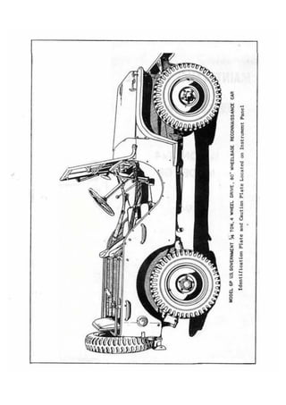
  • 1. 7 - - MOOU GP U S OOVERNMENT & TON, 4 WHEEL DRIVE, 80' WHEELBASE RECONNAISSANCE CAR Identification Plate and Caution Plate Located on Instrumart Panel
  • 2.
  • 3.
  • 4.
  • 5.
  • 6.
  • 7.
  • 8.
  • 9.
  • 10.
  • 11.
  • 12. 0-3 2 FORD TRUCK WTON 4 x 4 hginc Oiling System - Fig. 7 LUBRICATIW Batore considering the details in con-nection with lubrication of modern motor vehiclea, i t is ~saential to underatand h#we of the canditiaw which are enowrntered in such vthiclea, In the first place moet of the moving parta are manufactured to a high degree of prcciaian and are fitted to very cloae limits. Lubricants for audr parta must be capable of penetrating be-tween these closely fitted parts quickly and maintain their lubricating qualities under high operating teaperaturea. D i f - rerent qualities in lubricants are re-quired Tor different parta of the car due t o the mrying degree8 of pressure, he8t qr friction. Engineers have made a careful study to qetermlne what type of lubricant will mst effectively cdmt frictian and reduce heat i n each of the various unit8 of which a motor vehicle is -riaad and the impart-ance of adhering closely to the factory recommendations as to lubricant cannot be over emphasized. To f u l l y appreciate the importance bf using the sight lubricant in the right place, a ~lotor.vJliclca hould be camidercd aa a group of .=tirely differaat mechanical units, many qf Mich perform a differcnt'function. For t h i s reaaon they must b l lubricateb with a lubricant sa-pecially deeigned t o combat a degree of heat, friction or pr,eaaure encountered in that oarticular d t . The particular t y p e o f lubricant for each point is covered in the Lubrication Chart.
  • 13. TRUCK As illustrated in Figure 7, the engine is lubricated by pressure feed to the main connecting rod and camshaft bearings and by splash t o other p a r t s . The gear-type Oil Pump Housing is cast i n t ~ g r a lw ith the f r o n t Main Bearing cap and is driven from the crankshaft gear of the timing gear set. The oil pressure re1 ief and segulat ing valve illustrated in Figvre 8 lifts at 30 pound pressure which will show a gauge pressure f ran 15 to 30 pounris on the inst mat panel depading on the temperatures of the oil and speed of t h e engine. The oil in. the agine when shipped from the factory is sat isfactory for the f i r s t 300 miles. Arter this period of operation, t h e engine o i l should be drained and replaced with new oil of the correct viscosity as shown below: 1 Oil Relief Valve - F i g . 8 PREVAILING TEMPERATURE RANGE: S.A.E. viscosity No. precautionary measure toward preventing accumulation of sludge or foreign mattes on the screen, it is suggested that this screen be cleaned i n gasoline before the plug is replaced. OTL CHANGES Under normal driving conditions, t h e engine oil should be changed every 2,000 miles. By normal d r i v i n g conditions we mean within temperatures ranging from 32 degrees Fahrenheit t o approximately 80 de-grees,~ m edium road speed and average dust conditions. In extremely cold weather when condensation and crankcase dilution might cause the formation of sludge in the crank-case, the oil should be changed more fre-quently. This procedure should also be followed with units which are operated infrequently and f o r short periods during cold wather. This type of operation promotes the accum-ulation of water in the crankcase result-ing from condensation and products of com-bustion within the engine. Such moisture and other contaminants are largely evaporated after the engine becomes thoroughly warmed up but under conditions such as those men-tioned above, they can be a source of cm-siderable trouble i f precautionary measures a r e not taken. Temperatures above 32 degrees 30 Fahrenheit Sectional View of O i l Bath Air Cleaner Fig. 9 Temperatures below 32 1 0 or 10-W WSTV TERl?ZTORY degrees Fahrenheit * Not withstanding the fact that the Ford engine is equipped with an Oil F i l t e r , as well as an Oil Bath Type Air Cleaner, the OIL, PAN DRAIN PWIG oil should be changed more freqV-znt lyw hen t h e units are operated under extremely It will be observed that the oil pump dusty conditions. The Oil Bath Air Cleaner screen is an integral part of the'oil pan should b e cleaned out as often as is neces-drain plua. Part 6730, Figure 82. As a sary t o keep the sump free from excessive
  • 14. FORD TRUCK accumulations of dirt. Under the most se-vere conditions t h i s might be necessary every day although such extreme conditions are very infrequently encountered. The engine ventilator screen in the oil filler cap should also bc checked to see that i t does not become obstructed with dust. ADDING OIL Thc o i l Icvel should bc kept in the "safe driving r s n g e 1 f s s m a r k e d o n t h e oil l e v e l bayonet gouge shown in Figure 10. The five quarts of oil placed in the crank-case when the oi l is changed, brings tthe l e v e l slightly above the full mark on the measuring stick. It is not necessary to maintain the level at this point and oil should not necessarily be added u n t i l the level is down toward the lower part of the Nsafe driving rangen indi-cated on the gauge. 1 I t is advisable t o wait several minutes a f t e r the engine has been stopped be-z fore checking the o i l l e v e l , F*I = A considerable quantity of rml = oil rcmains in the circu-l a t ing system f o r . a sdort Oil Level p e r i o d after the engine is Gauge stopped <and the oil level Fig, 10 gauge w i l l not register ac-curately until this o i l has had s u f f i c i e n t time to drninnback i n t o the o i l pan. OIL FILTER The oil f i l t e r unit should be changed a f t e r 8,000 t o 10,000 miles of operation. The cleaner elcrnent and case are manufac-tured as a complete unit and the entire element must he changed (See Figure 11). To changc t h e o i l f l l t c r , disconncct the o i l l i n e a t both top and bottom of the liltcr unit. Remove the oil gauge unit which is screwed i n t o the top of the oil f i l t e r . Loosen t h e two cap screws which hold the filter bracket to the cylinder block and r h e clamp screw loca'ted between the f i l t e r and thc cylinder block. The f i l t e r unit can then be pulled upward out of the bracket. Install the new fitter unit i n t o t h e bracket on the engine and tighten the clamp screw. Then install the o i l gauge unit in the new filter and connect both the - r - O l r l l t l top and hot tom o i l 1 ines Sectional View of to the connections on Oil Filter Unit the filter unit. Fig. 11 TRANSMISSION AND TRANSFER CASE b t h the transmission and transfer case should be lubricated with SAIZ 90-EF gear o i l if such lubricant is available. Since the s e l e c t i o n of lubricants is necessarily restricted in field operations, alternative lubricants which may be used in t h e trans-mission are SAE 70 oil or lubricants con-formlng to Quartermaster Corp s p e c i f i c a - tion W-L-761 Class No. 2, For the Trans-f e r Case, SAE 70 oil may be used. The same type of lubricant should be used for both m r and winter operation and the level should be maintained even with the filler plug. It is suggested that the lubri-cant be changed every 5000 miles or eqeh fall or spring, whichever should occur first. FRONT AXLE AND W E . Wypoid gears are used i n both the front and rear axle and it is, therefore, neces-sary to use a lrHypoid Extreme Pressuren type of lubricant. Gear lubricant con-forming to Quartermaster Corp spccifica-tion W-L-761 Class No. 2 is of this type and should be SAE 90 viscosity. Avoid mixing various brands of Hypoid lubricants. I f the brand is changed, it is e s s e n t i a l that the rear axle housings b e drained and flushed with l i g h t engine o i l before installing the new lubricant. 7 FRONT AXLE UNIVERSAL JOINTS massis Lubricant conforming to Quarter-master Corp specifications ES-444 Type No, 1--Grade No. 1, should be used to lubricate these parts. Approximately 1/2 lb. (112 pt.) is required in each teer ring knuckle joint housing. Remove the plug shown in Figure 6 to inject the lubricant.
  • 15. FORD TRUCK PERMANENTLY LUBRICATED PARTS WHEELS AND TIRES The following parts arc packed with lubricant at the factory and will not re- Pressed steel, drop center rim wheels quire the addition of any lubricant unless which were especially designed for this disasscmbl y of the parts t)ecomcs necessary uni t , are used on the Ford Reconnaissance for some other reasons. and Command Car. The wheels are 16'1 in diameter, have a 4" rim, 5-1/21! bolt circle Front and rear propeller shaft and five bolt holes. They are fitted with Universal joints either 550 x 16 tires or 600 x 16 tires. Clutch throw-out bearing In cithcr case the correct inflation pres- Clutch pilot bearing sure is 24 pounds. Water pump Themost important factor controlling tire life is the air pressure in the tire. Tire In even' the flyvlleeli s inflation should, therefore, be checked at least once each week and every precaution f ram the a-~infeo r any reason, it will, of taken to prevent operati on of the vehicle course, be necessary to re-pack the pilot with tire pressures less than 20 pounds. bearing with a lubricant having a high Under-inflation not only decreases tire melting point, such as ES-444> 'ype J' life but also adds to the possibility of Grade 2. a rim bruise. STEERING GEAR The level of the lubricant in the steer-ing gear should be checked each 1000 miles and ifnecessary, addGear Lubricant W-L-761, Class No. 2. This will apply to either summer or winter operations. SHOCK ABSORBERS The shock absorbers should be refilled every 5,000 miles with Ford Shock Absorber Fluid. When refilling an instrument, clean i t thoroughly around the filler plug be-fore removing the plug, An extremely small particle of dirt inside the instrument might cause i t to become inoperative. Rim bruises are causedbythe tire hitting a curb or some other object with sufficient force to pinch the tire between the object struck and the rim. Several cords may be broken in the second or third layer of fabric but the tire will not show any outward signs of an injury. These cords will gradually wear on other cords until a bre'ak occurs. One of the most important reasons for close at tent ion to inflat ion pressures is the fact that this vehicle has four wheel drive. When both front and rear axles are driving, the rolling radius of all wheels must be equal in order to avoid prematute or ex-cessive wear in the axle differentials. CHASSIS FITTINGS CHANGING WHEEL AND TIRE The Lubrication Chart, Figure 6, clearly indicates the various fittings to which To change a whccl and t i re asseml~ly, the chassis lubr icarlt should be applied. A proceclure outlined below should be followed: semi-fluid lubricant intended for use in Y a pressure gun should be injected into these articular fittings. Every fitting should 1. ~pply the emergency brake. be wiped clean before the pressure gun is applied so as to avoid forcing particles of dirt or abrasive into the parts which 2. Block one of the wheels resting on the are to be lubricated. ground with a large stone or block of wood.
  • 16. FORD TRUCK 3. Place jack under a x l e close to the spring seat of the wheel which Is to be removed, and jack up car until wheel is a t lea'st 1 " clear of the ground, 4 . Remove t h e f i v e nuts holding the wheel t o the hub. See Figure 12. The wheel can then be removed. REMOVING TIRE EROM WEEL Deflate the tube completely. Loosen both beads from bead seats on, rim, Force the outside bead from the bead seat i n t o the rim w e l l at a point apposite ihe valve. Be sure the ,,, bead is in the rim well, then with two Fig. 11 t i r e tools placed approximately 4" on each side of the valve, l i f t the bead closest to you over the rim f l a n g e . (See Figure 1 3 . ) Follow around t h e flange with the tire tools until the outside bead is free from the rim. Then force t h e laaide bead into the rim well at until the entire bead is replaced. Always keep as much of t h e bead as possible in the rim well while installing the tire. Before inflating t h e tube, push t h e valve stem i n t o the casing as far as pos-s i b l e t o makc sure that the tube is not the top and pull Out the bottom the tire pinched under the t i r e beads. Do not let until i t as in Figure 13* go of the valve stem while doing this. , MOUNTING TIRE ON WIm: Inflate the tube until i t is f a i r l y rounded out and i n s e r t i t i n the tire. The tube must be placed in the t i r e with t h e valve stem a t the balance mark. Push t h e inaide bead of the t i r e into the rim well at the point next to the valve. Force the remaining portion of the bead over the outside flange of the rim. Do not attempt t o force t o o l a r g e a portion o v e r the flange a t one time. L i f t up on the tire, placing the outside bead i n rim well at t h e valve. Starting at e i t h e r side of the valve, force short length of the bead over t h e flange, continuing around t h e wheel I n f l a t e the tube to not more,than 2 pounds pressure, working casing back and forth. Proper f i t t i n g of t h e t i r e is in-dicated by the molded l i n e on the s i d e of the t i r e being equally spaced from the rim at a l l points, SPARE TIRE: The spare t i r e and wheel assembly i s mounted on the back o f t h e body and held i n place by three nuts. The bottom of t h e t i r e r e s t s on a support p l a t e which is bolted to the bumper. T h i s support plate has slotted holes so that it can be adjust-ed up o r down to provide adequate support for eitheq 5.50 or 6.00 size t i r e s .
  • 17. FORD TRUCK '&TON 4 x 4 1000-1 BRAKE SYSTEM , Brake System - Fig, 14 The system consists of a master cylinder The brake pedal, when depressed, moves in which hydraulic pressure is b u i l t up the piston within tho master cylinder; thus, by pressure on the brake pedal, 4 wheel sending the brake f l u i d from t h e master cylinders operating brake shoes against cylinder through the tubing and flexible each wheel drum when Pressure is applied, hose to each of the four wheeE cylinders. and the l i n e s msist ing of tubing, flexible hose, brackets and unions, interconnecting Brake f l u i d is plac'ed under pressure the master cylinder and wheel cylinders. each of wheel See Figure 14. the pistons t o move outward against the The master cylinder is fitted w i t h a brake shoes, bringing the shoes into con-piston, and the wheel cylinders are each tact with the See Figure 16= A s b f i t t e d w i t h two opposed pistons, a l l of PreSSUre on the brake pedal is increased, which are provided with cup packings, which greater hydraulic Pressure is buff t UP act as seals t o maintain pressure a d pre- within ,the wheel cylinders and cms.equently vent loss of brake f l u j d , greater force is exerted against the brake shoes. The ,system is self equal k i n g since a l l pressure is transmftted to the brake shoes by the column of f l u i d and no pres-sure can b e developed in any of the wheel cylinders or brake lines until the pres-sure is equally distributed at a11 points. # When the pressure on the foot pedal is . released, the retracting springs on t h e brake shoes return wheel cylinder pistons to their normal or nofffl position thereby. forcing the brake fluid back through . flexible hose and tubing into the mas. Brake Master Cylinder - Fig. 15 cylinder . - - the ter
  • 18. FORD TRUCK %-TON 4 x 4 THE MASTER CYLINDE3 Thc compensating-type master cylinder Fig. 15 performs two functions: 1. By means of the supply reservoir in the upper part of the housing, it maintafns a constant volume of f l u i d in the system at a l l times regardless of expansion, "heat-ing, n or contraction, "cooling." It also acts as a pump during the "bleeding1 operation. dust shield assembly or support plate, two brake shoes, the wheel cylinder assembly and brake shoe contracting spring. Figure 18 shows all parts of the rear wheel cyl-inder in their relative assembling positions. The wheel cylinders, are of the straight bore construction, being 1" diameter on the front wheels and 7/8" on the sear wheels. Exploded View of Wheel Cylinder-- Fig. 18 TO REMOVE THE WHEEL CYLINDER Should i t become necessary to remove t h e wheel cylinder for inspection, t h e following. operation should be performed: Disconnect the cylinder from the system by removing the inlet fitting and the bolts which hold t h e cylinder to the brake plate. Tt~e shoe travel is sufficient to permit the cylinder to be withdrawn without removing the brakc shoes, after the retracting spring has been disconnected. Wheel Brake Assembly - Fig. 16 lNSPECTION OF WEEt CYLINDER 2 . I t permits a d d i t i o n a l f l u i d to cnter the system to counterbala~ce any loss due After removing the wheel cylinder, from t o g r a v i t y seepage. the brake assembly, remove the baots,"Part No. 2206. from both ends of the cylinder.' piston and mp return to release position ~ h , Part No. 2196 and cups, Part much faster than the f l u i d in the lines. A 2201, a r e forced out of the b a r i e l by mmentarY vacuum is created in the cylinder the return spring pressure, Part No. 2204. barrel and additionel fluid is drawn i n t o Inspect t h e cups for ragged ends and the l f lc system from thc s ~ l > p l yrc scrvoir through bore for smoothness. the drilled holes in piston and past the l i p of cup. A f t e r fluid returns from the wheel cylinders, any excess of f l u i d in the system is passed through port into the reservoir; thus the cylinder is always full of fluid for the next brake application. WkEJL BRAKE ASSEMBLIES The wheel brake units are composed of a Should the bore be scratched or pitted, i t will be necessary to replace the cylin-der, to prevent lass of fluid or excessive cup wear . When re-assembling the wheel cylinder, all p a r t s must be f i r s t washed i n clean a l c o h o l , then dipped i n Brake Fluid for lubrication. Re-assemble t h e cup, Part Exploded View of Brake Master Cylinder - Fig. 17
  • 19. FORD TRUCK ',&TON 4 x 4 2000-3 2201, p i s t o n , Part 2196, and boor, Part 2206, in one end of the casting. The re-turn spring, Part 2204,and other cup, 2201, piston, 2196, and boot, 2206, are then in-stalled i n the other end of the wheel cyl-inder. The unit is now ready for instal-l a t i o n . N e w inlet fitting gaskets must be used when connecting t h e cylinder to the system. During this operation t h e master cylin-der must be kept filled with Hydraulic Brake Fluid, A master cylinder r e f i l l e r such a s the one illustrated i n Figure 20 should be secured in the event a large, a i r pressure refiller is not available. Fluid wi thdram in "bleedinglt operat ion -should not be used again. I BLEElINGHYDRAULICtINES I PEDAL ADJUSTmT Whenever a tubing Pine has becndia- Pedal adjustment is made as follows: connected a t t h e master c y l i n d e r , i t is necessary t o "bleedtj the hydraulic system I + a t a l l lour whccls t o expel g l l a i r . When-e v e r a l i n e is d i s c o n ~ ~ e c t efdro m any in-dividual wheel, that wheel cylinder only must be "bled.I1 Loosen the bleeder hose fitting, Part 2208, and s l i p on hose, Figure 19. Allow bleeder hose tohang i n clean container, such as p i n t jar. Depress the foot pedal slowly by hand; I allow return spring to return pedal "slowly" to I1offf'position. This produces a pumping ac-tion which forces f l u i d through the tubing and out at the wheel cyl-inder, carrying with i t any a i r that may be It is important that the link, Part 2143, Figure 17, be adjusted for clearance where i t seats in the piston. See sectional view, Figure 15. Should the link, Part 2143, be adjusted ti&tly against the piston, by-pass port may be blocked by the cup, Part 2173, and compensating action of the master c y l - inder will be destroyed. The primary cup, Part 2173, must be c l e a r of by-pass p o r t when p i s t o n is in its noffbT wr released p o s i t i o n . T h i s way b e determined by as-certaining i f there i s I/4" to 1/21' free movement of t h e brake pedal before t h e piston s t a r t s to move. Secondary cup (on 2169 assembly) pre-vents fluid from l e a k i n g out of the master cylinder into the boot. present. CAUTION: BEFORE REMOVING SUPPLY TANK Bleeding Wheel FILLER CAP, EXTREME CARE MUST BE USED TD Cylinder - Fig. 19 PREVEXVT DIRT FROM ENTERING THE MASTER CY-LINDER. DIRT GETTING LODGED BETWEEN TIE PISTONS IN THE SYSTEM AND THE CYLINDER Watch the flow of WALLS MAY CAUSE SPASMODIC BRAKE FAILURE. fluid f r o m h m , the end of which should be kept below the surface of f l u i d . Whenall a i r bubbles The use of other than an approved Brake cease t o appear and Fluid or the introduction of oil w i t h a when f l u i d stream mineral base or any unsuitable liquid will is a solid mass, cause the rubber parts to swell and become close bleeder con- * inoperative. Grit and abrasive substances nect ion. permitted t o enter :he fluid reservoir will T cause the cylhder barrel to become. scratched Ref i 111 ing Master and pitted. Wen either of these conditims Cylinder during occur, i t becomes necessary to remove t h ~ Bleeding Operation master cylinder for inspection and recon. Fig. 20 d l t ioning.
  • 20. ADJUSTMnVT FOR WEAR PRIPARING PARTS FOR MJ0R BRAKE mJUmT Brakes should be adjusted when the l i n - men major brake 'adjustmen t is required fngs have been worn to the extent that the or brake parts renewed, i t is recomntended pedal pad travels to within 1" of t h e toe that a l l brake d r m be removed and cleaned board on a hard brake application. and brake shoes and par.ts removed, cleaned and inspected as to condition of lining, CONNEGSION shoe return springs, hydraulic wheel cyl in-d e r s , e t c . ' During this inspection or disassembly of brakes, the hydraulic portion of the system should be left intact so that bleed-ing of the lines will not be required. This is readily accomplished by disconnect-ing the brake shoes from t h e cylinder a t t h e connecting l i n k s , without disturbing the hydraulic connections. The brake pedal must NOT be depressed at any time when brake drums are not in place. Brake Shoe Adjustments - F i g . 2 1 Brake drums should be approximately at room temperature when making adjustments. If brakes are a d j u s t e d when drums are hot or expanded, t h e shoes may drag when the drums cool and contract.. . . 1. ' Jack up a l l four wheels. 2 . Er,d play in wheel bearing should be taken up. REPLACING BRAKE: SHOES 1. Remove wheel and drum assemblies. 2 . Remove brake shoe retracting spring, Part 2061, Figure 22, Remove lock nut and washers from eccentric anchor bolts, Part 2037. Remove anchor bolts, Grasp brake shoes at the battom and pull sidewise t o release them from the brake shoe locating lugs and then remove the upper ends from the wheel cylinder. 3. Remove the rubber cups and pistons from the wheel cylinder. 3. Check pedal adjustment to make sure that pedal pad travels approximately 1/41' before master cylinder link end play has been taken up and master c y l i n d e r p i s t o n s t a r t s t o move. Repeat the following operations a t each wheel. . . 4 . Adjustment is made by turning t h e cam lrhn and "8" (Figure 21) with a wrench, in the direction of arrows, until the s h m s come in cantact'with t h e drum, then back off the adjustment slightly until the wheel Exploded View of Wheel Brake Assembly - rotates freely in either direction of ro- Fig. 2 2 t a t i o n . Proceed in a like manner on the btaFe shoes of a l l wheels.
  • 21. FORD TRUCK '&TON 4 x 4 2000-5 Examine all parts in the wheel cylin-ders and reassemble the units as outlined on page 20. Install the new brake shoes on the brake plate. Be careful that the upper end of the brake shoes are properly placed in the slots in the cylinder pistons. Install the brake shoe anchor bolts, Part 2027, eccentrics, Part 2028, lock washers and nuts. Leave the anchor bolt lock nuts sufficiently loose so the anchor bolts can be turned. Each anchor bolt is provided with a mark on the tang which indicates the high side of the eccentric, Set these two marks toward each other before instal-ling the brake drum. Reinstall brake shoe retracting spring, Part 2035. The above operation should be performed at all four wheels before proceedinq wit11 the work of adjusting the brakes. After reinstalling the hub and brake drum assembl ies and wheels, bleed the brak-ing system at all 4 wheels, as described on page 21. Apply from 25 to 35 lbs. pressure to the brake pedal. This pressure should be maintained while making the brake adjust-ment. Applying pressure to the brake pedal expands the brake shoes out to the brake drum. Using a small open end wrench, turn the anchor bolts C&D in the direction of the arrows on Figure 21 until each shoe barely touches the brake drum. Tighten the lock nut on each anchor bolt, making sure that the anchor bolt is held securely while the nut is being tightened, so as not to change the setting. Remove the pressure from the brake pedal and turn each wheel by hand to make sure that the shoes are not dragging. If there is any indication that a shoe is dragging, repeat the above operation more carefully. The above operation should be performed* for each shoe at all 4 wheels. After making sure that the eccentric anchor bolts are properly adjusted, as outlined above, the upper ends of the brake shoes should be adjusted to the correct clearance by turning the adjusting cams flAff and llBf1, Figure 21, in the direct ions indica-ted by the arrows until the shoes touch the drums. Then back them off very slightly so there is clearance between the shoes and the drum. This clearance should be approximately .008". BRAKE MAINTENANCE HINTS 1. Pedal goes to floor board. Cause : a. Normal wear of lining. b. Leak in system. c. Air in system, d. No fluid in supply tank. Remedy : a. When brake linings become worn, it is necessary to set the shoes into closer relation to brake drums. This condition i s usually accompanied by the remark from the driver that it is necessa.ry to PUMP the pedal several times before a brake is obtained. Shoes should be set as close to brake drums as possible wi thou) drag. Do not disturb anchor pins when making this adjustment. Adjustment must be made while drums are cool. b. A connection leak in the system will allow the pedal, under pressure, to go to the toe board gradually. A cup leak does not necessarily result in loss of pedal travel, but will be indicated by a loss of fluid in the supply tank. If no leaks are found at wheels or connect ions, remove master cylinder and check bore of barrel for score or scratches. c. Air in the system will cause a springy, rubbery actionof the pedal. Should a sufficient quantity be introduced into the system, the pedal will go to the toe board under normal pressure. System should be bled. 2. All Brakes Drag.
  • 22. FORD TRUCK Cause : a. Mineral oil in system. b. Port hole closed. Remedy: a. The introduction into the system of any oil of a mineral base, such as engine oil, kerosene, or the like, will cause the cups to swell and distort, making i t neces-sary to replace all rubber parts. Flush system with alcohol and refill with Ap-proved Rrakc Fluid. b. Directly ahead of the master cylinder piston cup, Part 2173, (when in normal release position) is a relief port. It is imperative that this port be open when the brakes are released. Should this port, Figure 15, be blocked by piston cup not returning to its proper release posi-tion, the pressure in the system will gradu-ally build up and cause brakes to drag. Opening a bleeder screw will allow built-up pressure to escape and give temporary relief. Bleeder screw must be tight be-fore car is driven. 3. One Wheel Drags Cause-a. Weak brake shoe return spring. b. Brakeshoeset tooclose todrum. c. Cups distorted. Remedy : a. Springs sometimes lose their contracting power and take a set. Replace spring. b. Readjust shoes to proper clear: ance. c. If in repairing wheel cylinders, kerosene, gasoline and other fluids are used as a cleaner instead of alcohol, the cups will swell and distort. The return action of the shoes will be retarded and the brake drum will heat. Replace cups and wash unit in alcohol and dip all parts in fluid before reassembling. 4. Car pulls to one side. Cause : a. Oil-soaked lining. b. Shoes improperly set. c. Backing plate loose on axle" d. Different makes of lining. e. Tires not properly inflated. f. Incorrect caster angle. Remedy: a. Replace with new Ford lined brake shoes. Grease-soaked linings cannot be salvaged by washing or cleaning. b. The construction of the brake is such as to cause a slight pull or drift if shoes are improperly set on the front wheels. On the rear wheels there will be no drift noticed, but one wheel will slide before the other. Re-adjust the shoes to proper clearance. c. Loose brake support permits the brake assembly to shift on the locating bolts. This shifting changes the pre-determined centers and causes unequal ef-ficiency. Tighten backing plates and re-ad j ust shoes. d. Different makes of linings have different braking efficiency. Two dif-ferent makes, one with high efficiency and , one with low efficiency, would cause car to pull to one side. Use Genuine. Ford brake lining. e, All tires should be properly inflated. f. Check front axle. 5. Springy, Spongy Pedal Cause : a. Brake shoes not properly ad-justed. b. Air in system. Remedy : a. Adjust brakes. b. Bleed brake system. 6. Excessive Pressure on Pedal, Poor Stop.
  • 23. FORD TRUCK %-TON 4 x 4 2000-7 Cause: The various adjustments on the emergency a. Drake shocs n o t properly nrI- Ijrake are c l e a r l y sltown i n t h e illustra-j u s t e d . tion, Figure 24. The procedure outlined b. Improper lining. below should be followed in making t h e c . Oil on lining. adjustments: Remedy : a. Adjust brakes, b. Replace withnewshoes and linings recommended type, as improper grades of brake 1 inings lose their gripping qua1 i t ies a f t e r a few thousand miles. c. Install new brake shoes and . 1 in inas. ADJUSTING THE EMERGENCY BRAKE The emergency ,brake is an external band 1. Set the hand brake lever in full re-lease position. 2. Wake sure the f l a t portion of the cam nFV, Part No. 2632, is resting on the ear of the brake band as shown in the illustra-t i a , Figure 24. If not, remove pin ltGgt so the cam will be free, 3 . Turn anchor adjusting screw "C" clock-wise" t o move the bqnd in toward the drum u n t i l a clearance ef .OIO+f is established a t t h i s point. Replace the locking wire. type mounted a t the rear of the transfer 4. Loosen the lock nut Wfi and a d j ust case which operates on a drum fastened to screw "D" to establish ,010" clearance for the rear shaft* parts Of upper half af shoe. T i g h t e n the lock nut. t h e brake a r e shown in t h e i r relative as-sembling position in Figure 23. 5. Tighten adjusting nut "Blf until a clear-ance of .010n is likewise established for the lower half of the brake shoe. Fig. 23 F i g . 24 6 . Adjust t h e clevis on rod "En, Part No. 9 2826, so that it is exactly t h e ri&t length with hand lever in f u l l release position and t h e flat of the cam lrF1f resting on t h e ear of t h e brake band as pointed out in Operation No. 2. 7. Replace pin "Gfl and cotter p i p .
  • 24. 3000-1 FORD TRUCK %-TON 4 x 4 Exploded View of Steering Gear Assembly Fig,, 25 3507 Clamp - Steering Column 3509 Tube Assembly - Steering Column 3517 Bushing - Steering Shaft 3524 Shaft and Worm Assembly 3538 Plug 3539 Nut - Sector Lock 3548 Housing - Steering Gear 3 5 5 2 Cup - Steering Gear Bearing 3553 Cup - Steering Gear Bearing 357 1 Rol Zer Assembly 3575 Shaft Assembly - Steering 3576 Bushing - Steering Sector Shaft 3577 Screw - Adjusting 3579 Washer - Thrust 3580 Cover - Housing 3581 Gasket - Housing 3586 Shim - Sector 3590 Arm - Steering Gear 3591 Seal - Steering Sector 3593 Cover Plate Shim 3597 Worm Cover Plate 3598 Retainer - Oil Seal 3600 Wheel - Assembly *3618 Plate 3618 P l a t s 3626 Spring - Horn Butt on 3627 Button - Horn 3678 Bracket - Steering Column 3682 Shim - Steering Column f: 9( 0: v : wl a!' tl e: S1 - w: b4 f I
  • 25. FORD TRUCK %-TON 4 x 4 3000-2 1 STEERING GEAR The steering gear isthe worm androller type and has a reduction ratio of 18.2 to 1 All parts of the steering gear are shown in Figure 25 in their relative as-sembling positions and are marked with Part numbers so the parts can be readily identi-fied when referred to in the following in-struct ions. It is important the drag link be removed from steering gear Pitman arm, Part 3590, in order to effect a satisfactory inspection of other adjustments and a1 ignment of gear incar. Now revolvehandwheel todetermine if any stiffness exists. If so, too many shims have been removed or gear is mis-aligned in car. Means for mechanically eliminating all play within the mechanism have been pro- CORRmION OF MISALIGNMENT vided. In this type of gear, the major ad-justments are accomplished with the use of shims. The need for adjustment, how-ever, should present itself only after considerable usage. Before altering any adjustments, jack up front wheels of car and make sure that cause of complaint is not from some other looseness such as ball sockets, and so forth. Then make the following test. I INSPECTION FOR PROPD WORM EEARING ADJUSTMENT: Turn hand wheel about one turn toright from straight ahead driving posit ion. Hold securely in this position to prevent any oscillation when front wheels are shaken violently. Now have helper shake front wheels hard sidewise. This will enable any end play in worm bearings, Part 3571, to be felt at wheel hub. If any end play exists, worm bearings need adjusting. Be sure end play is felt, and not be confused with play or give in jacket bushing. Worm bearing adjustment should be correct before further inspection of gear is made. WORM BEARING ADJUSTMENT: Loosen four screws which secure worm, cover, Part 3597, 1/8 inch. Use a knife to separate the top shim, Part 3593, passing blade all the way around between shims,* and taking care not to multilatc the re-maining shims. Remove only one shim at a ) time between inspect ions, to remove end play. Care should be taken not to set up stiffness in worm bearings. Loosen the frame bracket bolts just enoygh to allow gear to shift in frame to line up at angle determined by height set-ting of instrument board gear bracket and retighten framebracket bolts. Now loosen instrument board gear bracket, Part 3678, and allow it to shift to match gear column position, and retighten. This will correct any possible misalignment of gear column. INSPECTION FOR END PLAY OF ROLLER SHAFT Turn hand wheel to either extreme and back an eighth of turn. Gripping Pitman arm, Part 3590, at hub, roller shaft should rotate freely without particle of end play. If any end play exists, adjust as required by means of roller shaft adjustment screw, Part No. 3577, Figure 25, at back of hous-ing. Be sure to lock SECUREZY with lock nut, Part No. 3539, at back of housing, and reinspect for end play and free rota-tion throughout whole gear movement. INSPECTION FOR PROPER MESH OF SHAFT ROLLER IN WORM (Never make inspection for proper mesh, without first correcting roller shaft and column adjustments described above. ) Turn hand wheel to the mid-position of its com-plete travel or turning limits (drag link previously disconnected), and shake Pi tman arm, Part 3590, to determine amount of lost motion. If this lost motion exceeds one-thirty- second of an inch, roller shaft ad-justment should be made. In this case, gear must be removed from car.
  • 26. FORD TRUCK IMPORTANT NOTE Before drag link is aga3n connected t o steering gear Pitman arm, Part 3590, swing front wheels throughout their tuning radius to determine ifany tight spots exist. There should not be rmre than 10 Ibs. pull on drag link either fore or aft throughout e n t i r e turning radius. WEN GEAR IS REMOVED FROM CAR Holding gear in vise and with column to right of v i s e , remove roller shaft, Part No. 3575, care being taken that all roller shaft shims, Part 3586, remain on roller s h a f t , so none w i l l drop i n t o housing be-hind worm, whiclr may cause interference with proper gear operations. Replace hand wheel on column. I f proper worm bearing adjustment has not been accomplished, read-just as per previous instructions. Note that roller shaft thrust washer, Part No. 3579, is assembled with chamfered s i d e next to r o l l e r shaft thrust face. ROLLER SHAFT MESH IN WORM Adjustment for closer mesh of the shaLt r o l l e r , P a r t 3575, w i t h the worm o r , in other words, elimination of excessive play at t h i s point, i s accomplished b y the re-moval of shims which arc in plach behind the roller shaft thrust washer. !ke Figure 26, Tl~e posi tfon of roller contact with warm is offset from the centerline of worm, hence whem a shim is removed, the roller is moved i n t o closer mesh with the worm. Select, through trial, the proper amount of shims to produce not more than ,006 inch play measured at end of Pitman arm, qnd without heavy drag on hand wheel, Remove only one shim, Part No. 3586, from roller ' shaft, and insert roller shaft i n housing. Then turn hand whecl nearly to left stop. Now hold r o l l e r shaft i n place with thumb pressure an hcad cnd of rollcr shaft, and revolve hand wheel t o the right until shaft roller is in center of worm. (Do nor re-vcrac turn toleft.) Still holding roller shaft with other hand, try to rotate i t . I f anyplay exists remove another shim and repeat operation until play felt by hand in center of gear is removed. WORM THRUST COVER SHIMS WORM COYER OVER !XRLWS OLUR SHAFT COYER ROLLER UHITT WXlUlTULMT $CHEW RQLLFR SHAFT COVER Sectional View of Steering Gear Fig. 26 When proper amount of shims have been selected, turn hand wheel close t o either stop and reassemble roller shaft cover, Part No. 3580. Tighten screws securely. (Drive Pitman arm, Part 3590, on roller shaft.) Now loosen roller s h a f t adjust-ment screw lock nut, Part No. 3539, and t ighten r o l l e r shaft adf ustment screw, Part No. 3577, until all end play in roller shaft has been removed, when gear shaft is rotated in this lash position near end of worm. Lock rcller shaft adjustment screw lock nut, Part No. 3539, and reinspect gear for freedom of operation throughout and absence of end play in roller shaft adjust-ment. her fol USC mec t I l€ act by - in: f l ~ tor - Shc rec SOC sf t
  • 27. FORD TRUCK 1h-TON 4 x 4 3000-4 LLBRICATION I Remove oil filler plug and vent hole cover, Part No. 3538. Fill with approved lu-bricant until it comes out of oil vent. Replace oil filler plug andvent hole cover to prevent dirt from entering housing. Avoid use of graphite, white lead, or heavy solidified oil. If these adjustment instructions arc followcd carefully andCORRECT lubrication used, proper funt ioning of the steering mechanism will result. Do not deviate from I these instructions to correct any erratic action of the front wheels, as evidenced by shimmy or steering wheel fight, but instead see that tires are properly in-flated and front axle checked for correct toe-in. camber and caster specifications. Shock absorber adjustment shbuld be at the recommended standard. Tie rod and drag link sockets or connections must also of neces-sity have no excessive looseness. not adjustable on this axle, as it is con-trolled by the manner in which the parts are manufactured. Any change in the camber angle can only be due to a damaged part, and such part should, ofcourse, be replaced. 4 Fig. 28 WHEP. ALIGNMENT CASTER The proper alignment of the front wheels is essential to insure normal tire life as well as to maintain ease of handling and roadability at the higher speeds. The first three factors which control this are the camber, castorand toe-inof the front wheels. The caster of the front axle is the back-ward tilt of the top of the front axle or in the case of this particular unit the top steering knuckle bearing. The best example of caster is the front forks and wheel of a bicycle. Byplacing the top steering knuckle bearing back of the center line of the front wheel, the weight of a vehicle tends to keep the front wheels lined up in the direction of travel. If there is insufficient caster, the front wheels would have a tendency to wander at th.e higher speeds If the caster angle is excessive, there is a greater tend-ency for the wheels to hold in a straight ahead position and it is more difficult to turn the wheels when parking the car. As shown in Figure 28, the correct caster angle in the Ford truck is 4 degrees. Fig. 27 CAMBER The angle that the wheel is tilted out- V ward at the top from a vertical line is known as the camber. The purpose of the ) camber angle is to place the load to a greater extent on the inner wheel bearing. As shown in Figure 27, the correct camber angle of the front wheels on the Ford truck is one deg. 30 min. The camber angle is Fig. 29
  • 28. 3000-5 FORD TRUCK 1h-TON 4 x 4 WHEEL TOE-IN. I t is necessary to a d j u s t t h e front A tendency for t h e wheels t o toe-out i 3 wheels so they turninslightly at the front, created by t i l t i n g t h e top of the wheel in order to offset the higher wear which outward, and t h e purpose of toeing the would otherwise result from the camber. wheels i n is t o counteract their tendency t o toe-out. The adjustment of wheel toe-in, is made by shortening or lengthening the spindle connecting rod. As shown in Figure 29, t h e correct amount of toe-in is 6 minutes m l m i - mum t o 12 minutes maximum. The adjustment is made by removing the cotter pin and lock nut which holds the s p i n d l e connecting rod to the spindle arm at either end, Discon-nect t h e rod from t h e arm and loosen the clamp nut, Figure 30. Then screw out the spindle connecting rod end until the cor- Fig. .30 I rect adjustment is secured.
  • 29.
  • 30.
  • 31.
  • 32.
  • 33.
  • 34.
  • 35. FORB TRUCK tinue pressing down at various points on the internal part, until each ball can be ra:~oved. This operationis facilitated by Removing Universal Joint Cup - 2nd Operation - Fig. 41 using a screwdriver in the manner illus-t r a t e d in Figure 39. Do not exert the slightest amount of force as the purpose There are two long, elongated holes in the cage, Part 3215,in addition to four smaller holes. Turn this part as shown in Figure 42 so the two elongated holes are in the position illustrated. This will permit the cage to be lifted out of the. outer housing. Removing inner race from cage - 1st Operation - Fig. 43 To disassemble Parts 3215 and 3221 turn Part 3221 so one section can be pushed up into one of the elongated holes of Part 3215 as shown in Figure 43. The bottom part can then be swung out of the outer ring as shown in Figure 44. Removing Universal Joint Cage Fig. 42 is merely to overcome the suction of the grease. After a l l the balls have been taken out, the inner part of the assembly can be turned freely. Push down on one edge of part 3215 so the cup, part 3219 will be on top, (Fig-ure 40) and then remove the cup. 9 Removing inner race from cage - 2nd Operation - Fig. 44
  • 36. 4000-8 FORD TRUCK REMOVING AND OVERHAULING DIFFERENTI[& DISASSEMBLING DIFFERENTTAL ASSEMBLY SHOUP FDR LOJUSltMG -. Sectional View of Differential Ffg. 45 To remove the differential assembly, the procedure outlined below ahwld be followed: 1. Rtm~vc a x l e shafts, 2 . Drain differential and remove the d i f - ferential covcr, Part 4015. 3 . Remove the four bolts which hold the two differential side bearing caps in po-sition. See Figure 5 5 . 4 . Using two pinch bars as illustrated in Figure 46, pry out the differmtfnl and ring gear assembly. Removing Differential Assembly Fig. 46 1. Remove the cap screws holding the ring Rear to the diffcrcntial casc. Rmoving Differential Gear Fig. 47 2, Remove the ring gear from the differ-ential case by tapping i t lightly with a lead hammer. 3. The differential shaft, Part No. 4211 is held in place by lock pin, Part No. 4241. Using a small punch, drive wt the lack pin, The d i f f e r h t i a l shaft can then be removed together with the other internal parts of the differential. Removing Differential Shaft Lock Pin Fig. 48 REASSEHEbTNG DIFFEIWVTIAL Carefully examine the surface of the-diiferential case on which the ring gear scets,*as well as the ring gear to make sure there are RO foreign particles or burrs on the two contacting surfaces. Line up the cap screw holes in t h e ring gear with thosc En the differential case and then drive the gear into position on the cnseby tapping i t lightly witha lead hammer.
  • 37. FORD TRUCK %-TON 4 x 4 4000-9 The relative assembling position of the internal parts of the differential are shown in Figure 31. Reassemble the differential pinions and thrust washers in place and install differential shaft lock pin. In order to prevent the lock pin from working out, use a punch t o peen over some of t h e of the differential case as illus-trated in Figure 49. Reinstall the cap screws which hold the ring gear t o the differential case. After t h e cap screws have been tightened uni-formly, make certain that t h e cap screw locks are bent securely around the cap screw heads so there I s no possibility of the screwa working loose. Fig. 49 DI~ERE'VI& CASE BEXRLNGS There should b e a t i g h t f i t of ,008n between the axle housing and the differcn-t i a l bearing cup. This clearance should be checked as illustrated in Figure SO by installing the ring gear and differential assembly in the housing. If the clearance between t h e bearing cup and housing is in-correct, remove the differential case bear-ings with a puller such as that illustrated fn Figure 51. , . F i g . SO The f i t of t h e differential bearing cups is controlled by the use of shims, Figure Fig. 51 52. These shims are supplied in thick-nesses of ,0031; ,00511, .010and .03011. After removing the bearings as described above, measure the thickneas of the shims and add or subtract a suffi-cient number to ob-tain a snug .008fl fit in the housing. ' Fig:52 - A f f e r the re- - quires thickness of shims has been de-termined, install the shims and bear-ing cone an the dif-ferential case, us-ing an arbor press as illustrated in Fighre 53. Fig. 53 Reinstall the differential assembly in the housing. This operation can be f a c f l - Ztated by cocking the bearing cups slightly as shown in Figure 54 when the differential is placed in the-housing and then tapping them lightly with a lead hammer. After the bearing cups are firmly in place in t h e housing, reinstall the differential bearing caps. Xt is important that the caps be reinstalled in the same position
  • 38. 4000-10 FORD TRUCK Total back l a s h between the ring gear and pinion should be withi; .005" to .007". This can be checked by mounting a dial indicator on the rear axle housing as shown in Illustration 56 with the button of the indicator against one of the gear teeth. Moving tpe ring gear by hand will indi-cate the amount of back lash. Pig, 54 in which they were originally assembled. This can be detcrrnined by observing the p o s i t i o n of the numerals in each cap as illustrated in Figure 55, Each cap should he installed with the numerals on the cor-responding side of the housing. Fig* 55 After securely tightening the differen-t i a l bearing caps, check the back fa& of the r i n g gear f o r run out in the manner ahown in Figure 57. A totat indicator read-ing in excess of .003 indicates a sprung differential case or an improperly installed ring gear. In e i t h e r case, t h e assembly should be taken apart and re-checked thor-ough 1 y . Fig. 57 In the event the back lash is not with-in the limits mentioned above, it will be necessary t o change t h e shims back of the differential case bearings. Figure 52 shows the shim which should bechanged to secure the desired amount of back lash. Changing the position of the ring gear -005 to one s i d e o r the other w i l l change t h e amount of back lash approximately the same amount. In order to assist in determining whether thc gcars are properly adjusted, paint the ring gear with red lead or some other sub-stance of this kind and turn the ring gear so t h e pinion will make an impression on the teeth. The correct procedure t o fol-low i n the event of an unsatisfactory tooth contact is shown in the Chart Figure 59. COMPRESSING COLLAR OIL SEAL ASSY. OIL SEAL GASKET PlNlON HOUSING Fig. 56 Fig. 58
  • 39. FORD DRIVE COAST - * .&-" *., " * zq;$E.-. "I% TOE END F1G.I. IDEAL RING GEAR TOOTH FIG.2. HIGH TOOTH CONTACT-TO CORRECT HEEL END CONTACT- UNDER LIGHT LOAD MOVE PINION TOWARD GEAR m q j i i f F = = . ~ T ~ FIG.3. LOW TOOTH CONTACT-TO FLG.4, TOE CONTACT-TO FIG.5. HEEL CONTACT-TO CORRECT MOVE PINION AWAY CORRECT MOVE GEAR CORRECT MOVE GEAR FROM GEAR AWAY FROM PfNlON TOWARD PINION Fig. After the gears have been properly as-sembled and adjusted, the pinion shaft o i l seal, Part No. 4676 should be i n s t a l l e d . A s a t i s f a c t o r y tool for i n s t a l l i n g t h i s oil seal can be secured from Hinckley Meyers C o . , Jackson, Michigan. As illustrated in Figure 58, the pinion shaft nut, to-gether w i t h t h i s tool, is used t o press the new ail seal into place, after the mi-versal j o i n t end yoke has been removed. The end yoke, Part No. 4842, should then be reinstalled. ADJUSTING PINIOFY BEARINGS Before attempting to adjust the ring gear or differential parts, the rear axle pinion should bc carefully checked and nd-justed, Adjustment of t h e pinion is ac-complished by t h e use of shims between the G! LJ U Fig. 60 bearing cups and the housing. See Figure 45. These shims are available in thick-nesses of ,003, ,005 and .010. 59 Proper adjustment of the rear axle pinim necessitates t h e use of a precision tool such a s t h a t i l l u s t r a t e d i n Figure 60. This pinion setting gauge (HM J-5895) is fitted with a micrometer for measuring the thickness af the shims required t o properly locate the pinion in the differential haus-ing so i t will have correct tooth contact with the differential gear. Fig. 61 A l l axle pinions are marked with an ~ l e c - t r i c needle on the ground surface on the ends of the pinions t o show the correct setting. A pinion masked zero (0) will show a reading sf ,719" an the micrometer, when properly adjusted. (The dimension .719 merely represents the zero cone setting wfien t h i s particular micrometer gauge is used.) Therefore, a pinion marked "Plus 21"s -902 longer than the mean dimension and will show a micrometer reading of .717 when properly adjusted. Likewise, a pinion marked Minus 4 is .904 shorter than the mean dimension and w i l l show a micrometer reading of .723'bhhen properly adjusted.
  • 40. 4000-1 2 FORD TRUCK In order to remove the axle drive pfn-i o n , i t is necessary t o disassemble the propeller shaft end yoke Part No. 4842 frm t h e pinion shaft. T h i s is accomplished by use of a puller such as that illustrated in Figure 62. Pinion Shaft b d Yoke Puller Fig. 62 The pinion i s removed from the housing by placing a brass d r i f t an the forward end of the pinion shaft and driving I t out of the forward bearings with a hammer. After the pinion is free of the forward bearing, i t can b e easily lifted out from the rear of the housing. Removing Pinion Shaft Rear Bcnring Fig. ,63 The rear beating can bc removed from t h e pinion s h a f t by using n bearing re-mover suda as that illustrated i n Figure f~3, and pressing i t o f f on arbor press, To reinstall the rear bearing cone, use a length of pipe of s u i t a b l e diameter so it will press against t h e bearing cone and pat against the retainer. I t can then be premed on in an arbor press as illustrated in Figure 64, Fig. 64 A suitable tool for removing and instalG ing the bearing cups in t h e differential hausing is illustrated in Figure 65. The forward bearing cone and oil seal assembly Fig, 65 should be driven out of the housing toward the front. Tf the rear bearing cup is t o be changed, the pinion rear bearing cvp should bg raovedas illustrated in Figure -66 Due t o the fact the proper meshing of the drive pinion with the ring gear is con-t r ~ l l e db y the number of shims behind the rear bearing cup, it is imperative that the correct thickness of the required shims be determined with a micrometer. BY using the pinion s e t t i n g f i x t u r e described an
  • 41. FORD TRUCK %-TON 4 x 4 4000-13 Fig. 66 page 40, the thickness of the shims rises-t o su-a ~ortt he ini ion as illustrated in m Figure 69. Do not i n s t a l l the pinion o i l s e a l until t h e pinion setting has been - sary to secure proper pinion setting, was Fig. 68 previo~syl determined. After measuring the t h i c b e s s of the s,hims as shown in Figure m-cl-mked with the pinion setting fixture, 68, place them i n the differential hous- p r e v i ~ u s ld~e s c r ibed and illustrated in ing and replace t h e rear bearing cup as Fiwre shown in Figure 67. Fig. 69 / Fig. 67 The correct pinion bearing adjustment is obtained by using shims between the pin-ion bearing spacer, Part No. 4668, and the front bearing cone. These shims must be of t h e same thickness as the shims p l a c e d behind the rear bearing cup and should be measured carefully as shown in Figure 68. Reinstall the pinion and rear bearing i n the housing, place the front bearing in position and then reinstall the propeller shaft end yokc. This operation can k per-formed very easily by using a block of wood REF&ACING STEERING KNUCKLE BEARINGS Replacement of the bearings or bearing cups in the steering knuckle necessitates removal of the hub and brake drum assembly, wheel bearing spindle, axle shaft and mi-versal joint assanbly, as well as the steer- $ng knuckle. Follow t h e procedure out-lined on Page 4000-4 for removalof a l l parts up t o the steering knuckle, The steering knuckle should be disassembled as outlined betaw: 1 . Remove the eight screws which hold the oil seal retainer in place, Part No. 1089.
  • 42. 4000-14 FORD TRUCK 2. Remove the four nuts holding the lower cap and arm assembly, Part No. 3128, to the steering knuckle. 3. Remove the four nuts holding the upper steering knuckle cap, Part No. 3113, i n place. The steering knuckle support and bearings can now be removed from t h e axle end. 4 . Wash a l l p a r t s in gasoline or other cleaning solution and inspect bearing and races f o r scores, cracks or chips. A l l damaged parts should, of course, b e re- ~eplacing p i v o t bearing cups. F i g . 70 In the event the bearing cups are dam-aged in any way, they can be removed by t h e use of a suitable driver such as that illustrated in Figure 70. The same driver should be used for driving the bearing cups into the axle end. REASSEMELING STEERING KNUCKLE SUPPORT Merely reverse the procedure outlined above to reassemble the units. When re-installing the steering knuckle caps, Part Nos. 3140 and 3112, sufficient shims must be installed between the cup and steering knuckle support so the proper tension will he maintained on the steering knuckle bear-ing. The shims are available in thick-nesses of .003, .005, .010 and .030. Ordin-a r i l y i t is merely necessary to replace the shims which were originally installed i n the axle at the factory. This can be checked, however, by using a checking scale of t h e type illustrated in Figure 87. In-stall one each of the .003, .005, .010 and .030h shims over the studs on the steering knuckle. Install the caps (3113 and 3128) lockwashers and nuts and tighten seclrrely. Check the tension on the bearings by hook-ing the checking s c a l e - i n t o the hole in arm (3128). Add or remove shim until the load is approximately 4-1/2 t o 6 lbs. Make sure there a r e the same number of shim under both the top and bottom caps.
  • 43. FORD TRUCK 'h-TOM 4 x 4 4000-1 5 Rear Axle Aasernbly - Fig. 71 Nut - Wheel Hub R.H. Nut - Wheel Hub b.H. Hub h Drum Assembly Hub & Drum Assembly Bolt - Wheel Hub R,H. Bolt - Wheel Hub L.A. Lockwasher Retainer Cone 8h Roller Assembly Cup - Wheel Bearing Lockwasher. Retainer Plug - Cover Vent. Case - Differential Gear Ring Gear and Pinion Shaft - Differential Pinion Pinion - Differential Conc nnd Roller Assembly Cup - Differential Bearing Cap - Differential Bearing Washer - Thrust Shim - Differential Bearing Washer - Thrust Shaft Shaft Gear - Differential Pin - Lock Strap - Screw Lock Cup - Pinion Bearing Rear Cone and Roller Assembly Cup - Driving Pinion Cone and Roller Assembly Shim Shim Casket - Oil Seal Shield - Dust Spacer - Pinion Bearing Retainer Flange - Axle End
  • 44. FORD The rear axle is a full floating type and has exactlythesame differential, pinion and gear and differential housing as the front axle. An exploded view showing all the parts in relative assembling position is shown in Figure 71. The instructions in the foregoing para-graph concerning repair and adjustment of the front axle, pinion and ring gear as well as the differential, will apply ,in their entirety to the same parts in the rear axle. .Therefore it is suggested that you refer to the front axle section in the event information is desired concerning the ser-vicing of these particular parts in the rear a x l e . I Sectional View of Rear Hub and Brake Assembly - Fig, 72 AXLE !MAIT The rear axle shafts are the full ffoat-ing type, which means that the load is car-ried entirely on the axle housing. The only purpose of the axle shaft in this type axle is to turn the wheel hub, and this is ac-wllshed by splines mthe inner end of the shaft which fit into the differential, and a 'flange on the outer end which is bolted to the hub by six cap screws. The axle shaft flange bolts take the driving thrust and are thereforea very close ftt in both the axle shaft flange and the b p l t holes in the hub. The bolts are se-cyred by lockwashers, but it is highly im-portant that these bolts be checked fre-quently so as to make certain they are kept securely tight. To remove an axle shaft, it is merely necessary to take out the six studs which bolt the driving flange to the hub. If the flange sticks to the hub slightly, it can be pried loose with a screw driver or other similar sharp pointed instrument. When replacing the axle shaft, make sure the paper gasket is in place on the flange. PROPELLER SHAFT Power is transmitted from the transfer case to front and rear axles by means of propeller shafts such as those illustrated in Figure 73. Both propeller shafts have universal joints at both front and rear ends. Both shafts are the tubular type and have the universal joint ends welded to the tube on the axle ends. The.universa1 joints which bolt to the companion flanges on the transfer case are slip type joints, as illustrated in Figure 73. With this type of joint,. movement of the spline shaft in the joint compensates for variation in the distance between the transfer case and the axles as the axles move up and down. Each universal joint consists of two yokes, a cross, needle bearings and cap. As illustrated in Figure 73, the 'needle bearings are held in place by snap rings and can be replaced as described below. The propeller shaft is removed from the vehicle by taking out the four boIts at the transfer case end which hold the universal joint t o the companion flange and the four U-clamps on the universal joint at the rear axle end. This applies to both the front and rear propeller shaft. DISASSEMBLING PEZOPEUIE;R SHAFT UNIVERSAL JOINT: Remove the snap rings, Part No. 7096, by pinching fie ends together with a pair of pliers. If a ring tends to stick in the groove, tap the end of the bearing, Part No. 7074, lightly so as to relieve pressure against the ring. Use a soft round drift witla a face about 1/32 of an inch smaller in diameter than the hole in the yoke to drive out the
  • 45. FORD bearing. Hold the universal joint yoke in a vice and drive on the upper bearing until the lower bearing I s pushed out of the yoke. Then turn the joint over in the vice and d r i v e on the exposed end of the- journal cross, Part No. 7084, to push the other bearing out of the yoke. Repeat t h e above operation t o remove t h e other two bearings. The journal cross assembly can then be lifted out by tilting it toward t h e open end of the yoke. Wash all parts In gasoline and if there is no evidence of wear, repack with a good grade of semi-fluid lubricant (140 S.A.E.) . Make sure the reservoir in each journal trunnion is f i l l e d . With t h e rollers in the race, f i l l the race about one-third f u l l . Installing Universal Joint Bearing As a precautionary measure, i t is ad- Fig. 74 visable t o install new oil seal, Part No. transfer case ends o f ' t h e propeller shaft, 7078, on the journal cross assembly. The joints at the axle ends of the propel- 7084- Exploded View Propeller Shaft and Universal Joint F i g . 73 REASSEMBLING UNEVERSAL JOINT: Reinstall the journal cross assembly i n the yoke by inserting one end in the bottom hole in a tilted position a d then slide the upper part of t h e yoke over the upper part of the cross. In order to prevent the needle rolls from dropping out of the bear-jng race, hold the bearing in a vertical p o s i tim as f liustrated in Fi&re 74, and fn-sert i t in the yoke from the bottom. As soon as t h e bearing is in place, install the eplii ring retainer, making sure i t is firmly seated in the groove. Repcat this operation until a l l four bearings are i n place. ~f the joint appears to bind after being assembled, tap the lugs lightly with a ham- Ger so as to re1 ieve any pressuie of the bearings on t h e end of t h e journal. The inst ructions given above apply prima-r i l y t o t h e s l i p type j o i n t s used at t h e l e r shaft are the U-bolt type. With t h i s type of joint, two of the n e e d l e bearings can be readily removed by merely taking off the four nuts and lockwashers which h o l d t h e U-bolt to the universal joint. The ether two bearings must, of course, be driven out of the holes in the yoke by fol-lowing the procedure described above, FRAME AND S?RXNGS Due to the special requirements of a ve-hicle of this type, the frame incorporates a number of special features. The side members are flu* sections and are made af h?gh tensile strength steel. The impact bar actually acts as an extra cross member. The same is true of the skid plate which is riveted t o the frame in front of the trans-mission and transfer case as well as the gun amount support, Additional rigidity is provided by the p i n t l e hook brace and rear cross member assembly.
  • 46. 5000-2 FORD TRUCK Ih-TON 4~ 4 Exploded View of Frame Assembly Fig, 75 The various parts of the frame are cold riveted together. When repairing the frame, it is advis-able that this work be done with the con-ventional body mdframe straighta~ing tools. The application of heat t o straighten a ' frame is not recomended. When straightened cold, the metal does not lose any of its essential characteristics unless the bend or buckles are extreme. I f such a condi-tion exists, the parts should be replaced rather than straightened. FRAME ALIGNMENT The frame is the foundation of the ve-hicle and in addition t o carrying the load, must also keep the various units in correct alignment. Misalignment of the frame might cause difficulty in handling the vehicle at high speeds. It might also cause diffi-culty in shifting gears or keeping the trans-mission gears in mesh. I t is therefore ex- Another factor which will facilitate checking the Ford frame is that there is the same amount of upward curve (kick-up) at both the front and rear end .of the frame. The highegt points of the raised portion of t h e framd at both front and rear are 3-1/2~ higher than the top of the fJange in the center part of the frame. Knowing these two dimensions, there should be no difficulty whatsoever in de-termining whether or not the frame.is out of alignment, PINTLE HOOK I An illustration of the p i n t l e hook is shown in Figure 76. To open the hook, l i f t up on the latch and at the same time raise the upper part of the hook. The upper part automatically becomes locked in place when permitted to drop back into the normal tow-ing position, tremely important that every precaution be taken t o insure correct alignment of any new side members or cross members which may re-quire replacement as a result of an accident, Checking alignment of t h e Pard frame is a comparatively simple matter, due to the fact tpat the width of the frame is the same throughout its entire length, In other ' wards, the frame should measure 26-1/2" from the outside of the right side member to the oytside of the left side member at all ppints. Fig. 76
  • 47. FORD TRUCK Ih-TOM 4 x 4 SPRINGS t h e spring is to be changed and support it underneeth 'the frame so t h e wheels are Both f rant and rear springs are the cleat of the floor. If available, a chain semi-elleptic type. f rant springs have fall hooked to the end of the f reme is the 6 leave8 nnd the rear springs have 8 leaves most advisable method of raising the vehicle. 1111 - IHII . - - F - * Remove the four nuts holding the spring awt -4 --- -- *I#4 -==-* -- --.- ,- --::r;-- 4r =r;!;:; . e l i p s to the spring seats and remove the *PF-- Hz' , ,a+-- --: . m. 3- +ymxlo 1mspr-ing bseats. It is not necessary to dis-' - - 'K "UI" -- - ,,r.,.9 connect the shock absorker link unless t h i s 11111 I P L l Y G part is alao to be replaced. Remove the cotter pins from the castellated nuts and take off the shackle bar, Part No. 5468, at the shackle end of the sprhg. Removal of b31p -.- --Wid the strackle stud nuts at the other end dis- -1119. 1 1111 1V1191 connects the spring from the, frame. Exploded View of Front and Rear Springs Fig. 77 as ahom in the exploded view of the springs in Figure 7 7 . he front springs are se-cured to the frdnt end of the frame by shackla and mounted in a stationery bracket on the frame at the rear end, The axles a r e b o l t e d to the springs by clamps as fllustrated in Figure 78. 1 Spring, Shackles and Shock Absorber Linkage - F i g . 78 The spring shackle studs are the pre-lubricated type and do not require any additional lubrication throughout the life of the parts. With this t y p e of shackle stud, the outer shell of the stud must be held firmly in the spring eye so that a l l movement is taken up by the center part of the shack1 e stud. It is, therefore, neces- Removing Shackle Stud - Fig. 79 To remove the ahackle studs from the spring eyes, screw the puller 'on one end of the shackle stud and the acorn riut on the other end. Then use a large wrench t a tighten the puller nut untkl the stud is withdrawn from the eye. This procedure is illustrated in Figure 79. sary t o use special shackle stud pullers and renlacinq tools such aa those illus- Instafling Shackle Stud - Fig. 89 t t a t e d in Figure! 79 for t h e removal and The same tool is used for reinstalling rep'acafnt Of the studs t h e shackle studs aa illustrated in Figure ing front or rear springs, 80. It will be observed that t h e r e i s a slot in the edge of the puller for the pur- To remove any one of the four springs, polse of detcrmin'jng when the stud is pxmop-the procedure outlined below should be fol- erly positioned in the spring eye. Ccn- 1 owed : tinue drawing the shackle stud i n u n t i l an equal amount of the stud is visible -on Raise the end of the vehicle on which each side of the spring leaf.
  • 48. 6000-1 FORD TRUCK '%-TON 4 x 4 After installing the new shackle bolts the spring center bolt enters the hole in and hanger bars, make s u r e cotter pins are the spring sqt . It is also imperative that in place and securely fastened in the cas- every precaution be taken against damaging tellated nuts. Then install thespring seats the hydraulic brake tube on the rear axle and spring clips, making sure the head of when placing the spring clips over the axle. Sectional View of Engine - Fig. 81 ENGINE The engine is a 4-cylinder L-Head type C ~ L X W ~ having a cmter-balanced, cast a1 loy csank-shaft and aluminum pistons. A sectional The cylinder block, upper half of the view of the engine is shown in Figure 81 crankcase and flywheel housing are cast in and exploded views showing parts in t h e i r one piece. Water jackets are f u l l length, relative assembling posit ions are shown in extending completely around each ~ YinIde r Figures 82 and 83. and to the bottom of the cylinder walls, In this section the various parts bf the engine will be described in detail with the exception that manufacturing limits, etc. of the various parts will be omitted. These linlits will be found in the Specification Section of this book, p l e t e assemblies such as distributor, carburetor, starting motor, generator, etc., are usually described as engine accessories and a separate section is devoted to each of these units. The main bearing caps are bored with each individual block and must be kept intact with that wrticular block. The oil pump housing is an integral part of t h c front main bearing cap, CYLINDER HEAD The cylinder head is cast iron and is held in place on the cylinder block by 15 short, 1 medium and 2 long studs. A steel covered asbestos cylinder head gasket is
  • 49. Ehploded View Engine Assembly - Fig. 82 Engine Block Etc. 6010 Block - Cylinder - Asay. 6017 Cover - Cyl. Timing Gear Side 6018 Gasket 6019 Cover - Cy1. Front 6020 Gasket 6050 Cylinder Head 6051 Gasket 6066 Stud - Medium 6067 Stud - Long v 6520 Cover - Valve Chamber 6521 Gasket 6654 Spring - Oil Re1 ief Valve 6663 Plunger - Oil ~elief'v~lve 6666 Nut - Relief Valve 6675 Oil Pan Assembly 6700 Packing - Oil Pan 6701 Crankshaft Packing - Rear 6710 Gasket - Oil Pan R.H. 6111 Gaaket - Oil Pan L.H. 6750 Plug and Screen Assembly 6734 Gasket 6750 Indicator - Oil Level 6754 Tube - Indicator 6763 Pipe Assembly- Oil Filler 6766 Cap Assembly,- O i l Filler 8508 Cover - Water Pump 8513 Gaaket - Water Pump 9425 Manifold - Intake and Exhaust 9448 Gasket - Intake and exhaust hknifo 12410 Gasket
  • 50. 6000-3 FORD TRUCK 1/4-TON 4 x 4 mploded View of Engine Internal Parts - Fig. 83 Camshaft and Crankshaft a 6110 Piston 6135 Pin - Piston 6150 Ring -Piston 6200 Rod Assembly - Connecting 6211 Liner - Connecting Rod Bearing 6212 Nut - Connecting Rod 6150 Camshaft 6256-A Uear - Camshaft 6258 Ring - Camshaft Gear Locking 6393 Crankshaft 6306 Gear - Crankshaft 6310 Oil Slinger - Crankshaft 6312 Pulley Assembly - Crankshaft 63194 Ratchet - Crankshaft 6325 Bearing Cap - Crankshaft - Rear 6370 Bearing Cap - Crankshaft - Center 63g1 Liner - Crankshaft - Bearing - , Center 6433 Liner - Crankshaft - Bearing - Front and Rear 6335 O i l - Seal - Crankshaft - Rear Bear ins 6345 Stud - Crankshaft - Bearing Cap - Short 6346 Stud - Crankshaft - Bearing Cap - Long 6348 Castle Nut - Special 6375 Flywheel Assembly 651004 Rod - Valve Push 6505 Valve 6510-B Bushing - Valve Guide 6512 Retainer - Valve Guide Bushing 6513 Spring - Valve 6514-8 I?et*ainer - Valve Spring 6603 Body Assembly - Oil Pump 6614 Gear - Oil Pump Driving 6615 Tube Assembly - Oil Pump Inlet and Screen Cover r 6619 Gasket - Oil Pump Cover
  • 51. FORD TRUCK Ih-TON 4~ 4 600o-c used and a new gasket should be installed The piston pin should drop through the whenever the cylinder head is removed for pin hole in the piston with a total clear-any reason. The cylinder head nuts should ance not to exceed .0007" assuming, of be tightened with a torque indicating wrench course, that p a r t s are clean and pin and when the engine is warm to 50-foot pound piston are approximately the same tempera-tension. ture. PISTaV PIN The piston pins used in Ford four-cylin-der engines ar e rnanufact~~redto extremely close limits of precision, This is also true of the piston pin hole in the piston, as well as in the connecting rod. Conse-quently, any standard p i s t o n p i n may be assembled with any standard connecting rod or piston with entirely satisfactory re-sults. D d play pf the piston pin is controlled by means of wire' retainers which are ex-panded into graovcs in the piston pin bore of the piston. Reaming Piston and Rod to fit pin Fig. 84 The proper f i t of the connecting rod bushings to the pin can be checked by the following procedure: Hold the piston or pin in the hand with connecting rod extended downward in a ver-t i c a l position. Turn the piston, or pin, in a direction calculated t o cause t h e connecting rod t o move with the p i n as t h e a x i s . T h i s notion should cause the lower end of the connecting rod to move upward through approximately but not more than 1/21' arc before dropping back to a verti-cal position. In production standard piston pins are fitted in .000611 s l i p fit in the piston and .00025" slip fit in the rod. PJSTW RING There are two compression rings and one oil control ring on each piston. The lower compression ring and the oil control ring are of ths expander spring type. Khen Ford p i s t o n p i n s are awaflablc .002"* Ring Filing Block oversize. In cases where this oversize Fig. 85 p i s t o n pin is to be installed, i t is also fitting new piston rings, it is important necessary to re-work the piston and con- that the ring gap should be checked at the necting rod bushings. A combination ex- point in the cylinder bore, within the ring pansion reamer and burnisher (K,R.W. No. t r a v e l , where the cylinder diameter ia V-75) illustrated in Figure 84, should be smaller. The ring should also be square in used for this operation, the cylinder bore.
  • 52. FORD TRUCK The correct gap is from ,012" to ,0171' and this should be checked by inserting a feeler gauge between the ends of the piston ring. In most cases it k i l l be necessary to f i l e the end of the rim slinbtlv to secure the correct gap and a ring f i l i n g blbck such as that illustrated in Figure 85 will f a c i l i - t a t e t h i s operation, The tool can be se-cured from K. R.. Wilsm, Ehffalo, New York, under the No, V-109-B. Xn every case the piston rings should be f i t t e d in the particular cylinder bore in which they are t o be I n s t a l l e d . After f i t t i n g the rings so they have the proper gap, each ring should be checked in its respective ring groove on t h e piston to mukc sure i t , is free in the groove but does not have excessive clearance; t h i s can be done by rolling t h e back aide of the r i n g around the piston ring groove. Tatal side clearance in the groove should not exceed ,003". After installing the rings on the pis-tons, furn the rings so the ring gaps arc staggered and equal distance apart around the circumference of the pistons. This should be done so as to avoid havi6g the ring gapa inavertical pasitfon one above the other, VACVE SEAT INSERTS Tungsten chrome alloy steel inserts are used for both intake and exhaust valve sezl'ts. The i n s e r t s are s h m k by liquid air Lwfore they are pressed into the block and inas-much as the counterbore in the block is alightIy smaller i n diameter than the O.D. of the insert at normal temperatures, a tight f i t is insured. Because of their extreme hardness and abiljty to withstand high temperatures with-out becoming oxidized or p i t t e d , i t is rarely necessary to replace these inserts. Service equipment for t h i s operation is, therpfore, not considered essential for ordfnaryservice stations. d Cylinder blocks which re-quire replacement of a valve seat insert are os-dinarily returned to the factory for such work but in those rare instances where it is decided to equipashopto handle this type of repair, the valve seat replacing machine manufacturedbyHal1 Manu-f acturing Company, Toledo, Ohio, is suggested. Sectional View af Piston F i g . 8 6 . The aluminum pistons used In the Ford four-cylinder engines are wing type steel strut pistons. They are the f u l l s k i r t type and have two compressfon rings and one oil control ring located above the piston pin hole, When fitting pistons of this type, it is advisable t o use a p u l l . ' s c a l e such as the one illustrated in Figure 87. The pistons should be fitted t o 8 t o 1 2 Ibs. pull, wit11 a -003 Feeler. Piston Pull Scale Fig. 87 CONNECTING RODS The connecting rods in the Ford engine arc heat treated, carbod manganese steel forgfngs, They are accurately held to a specified weight so as to reduce vibration and lessen wear on bearings and pistons. The piston pin bushing in the connecting rod is of special bronze, * The correct procedure for fitting the piston pin in the connecting rod bushing is described En the foregoing section cover-ing piston pins. After installing a new piston or pin on a connecting rod, it is essential that the assembly be rechecked for alignment as illustrated in Figure 88.
  • 53. FORD TRUCK Checking Connecting Rod Aliment Fig. 88 me connecting rod bearings in the Ford four-cylinder engine are of the steel back replacable type with each half locked in position in the cmecting rods. The bear-ings are made of special bearing alloy, having high structural atsength which is bonded to a etetl core. ~S~ AND GEAR ASSEmLY A spccial alloy iron developed by Ford engineers is used in casting these Ford camshafts, This metal is highly wear-re- Timing Gear Marks F i g . 89 sistant and gives the shaft greater rigidity. The three hardened camshaft bearings are supported in t h e bearing holes bored in the cast iron block. A silent operating, durable camshaft gear made of aluminum is pressed on the camshaft. Replacement of this gear ia seldom necessary and for that reaaon, the ~amshaft and gear assembly is ordinari1.y supplied as a complete unit. I t is not advisable to attempt changing the gear on the camshaft without a fixture which has been especially designed for this purpose. Such a f i x t u r e is available from K. R. Wilson, Buffalo, New Yark and complete in- ~ t r u c t f o i l s as to procedure for changing the gear accompanies the fixture. When installing a new camshaft and gear assembly, the timing mark on the camshaft gear must be matched with the timing mark on the crankshaft Removing Crankshaft Timing Gear Fig. 90 To replace 'the camshaft and gear as-sembly, remove t h e cylinder front cover (6019) Figure 82, and valve chamber cover plate (6520). Then remove each of the valve guide bushing retainers (651 2) and insert
  • 54. 6000-7 FORD TRUCK %-TON 4 x 4 me bearings used in the Ford 4-cylinder engine are made from a special anti-friction alloy bonded to a s t e e l back. These are of the replacable type, and are clamped , in place by the main bearing caps described in the section devoted to the cylinder bid. I Crankshaft Main Bearing - Fig. 92 Install ing Crankahaf t Timing Cear Each bearing has a small lobe pressed Fig, 91 out of one s i d e , which is designed t o f i t these parts in one of the slats in each into a recess of similar size in the tiear-of the push rods in order to hold t h e s e ing cap. When f i t t e d in place, these lobes parts up the -haft is being prevent bearings from moving. See, Figure 92. The timing gear on t h e crankshaft is pressed on the end of the crankshaft and REAR BFARING O1L SEAL secured in place by a Woodruff Key, Tools for removing and installing t h i s gear are Details of the rear bearing oil seal shown fn Figure 90 and 91. are illustrated i n the sectional view of the engine Figure 81. Oil flowing from CRANKSHAFT rear bearing is d e f l e c t e d by t h e flange part on the crankshaft into t h e oil pan. The crankshaft is fully counter-balanced, cast alloy steel, with the counterweights cast integral. The crankshaft ia drilled f o r a i l passages t o the main and connect-ing rod bearings, Bearing surfaces are highly resistant t o wear and are especially smooth dbe t o t h e f a c t they receive two polishing operations after they are finish ground. The crankshaft is balmced withi'n 3/10 of an ounce inch. There are three main bearings which s u p ~ o r t the crankshaft and end thrust is t a k ~ nb y the flanges on the replacable cenler main bearing. A woven asbestos packing material is fit t ed in to grooves in the oi I p a and the upper part of the o i l seal to effectively prevent oil getting out the rear end of the engine at that point. .The upper half of the oil seal which ia fitted into the cylinder block, as well as the lower half are remova bJe pieces. FtWHEJ5 AND RING GEAR ASS-Y The cast iron flywheel used on Ford four-cylinder engines is very carefully machined and balanced so as to reduce v i - bration to t h e minimum. The steel starter ring gear is shrunk on t h e flywheel,
  • 55. FORD TRUCK Ih-TON 4 x 4 6000-8 When changing a flywheel ring gear, i t Total run out should not exceed .OlOn. is particularly important that the ring gear be heated sufficiently t o expand i t VALVE: PUSH RODS to a diameter larger than the diameter of the shoulder on the flywheel. A s u i t a b l e The one-piece Valve Push Rods i l l u s - gas heater for t h i s operation is available trated in 94, are cast a special K* R. hffaloy under wear resisting alloy iron developed by the the No. V-gl. Ford Motor Company for t h i s particular purpose. Being hollow, they are l i g h t in weight and the spiral openings in the side h e l p to provide sufficient lubrication, A 1 1 surfaces are hardened and these wear resisting surfaces in combination with the other parts of t h e valve mechanism, make i t possible to retain practically constant valve clearances. The customary valve ad-justing lock nuts and screws are not re-ouired with the Ford design valve mechanism. VALVES The Ford valves are high chrome nickel alloy steel because of the ability of t h i s rnctal to withstand high temperatures and corrosion. They do not warp, burn or p i t readily. This is true of both the intake and exhaust valve as the same metal is used for both. Pul ler for Removing FlywIleel Fig. 93 The operation of removing the flywheel from an engine is facilitated by the puller flIustrated in Figure 93 (K.R.W. No. TR-11). I f a puller of this type is not available, however, a flywhet21 can be removed by strik-ing I t f i r s t on one side and thm the other with a Rawhide hammer. In addition to the four bolts, there a r e two dowels in the crankshaft which h o l d the flywheel in place. The four bolts which hold the flywheel to the crank-shaft must be carefully wired after they have been p u l l e d up t i g h t l y . I t is also s u g g e s t e d . t h a t the flywheel be checked for run out a f t e r installation; t h i s can be done by f i x i n g a d i a l indicator to the flywheel-housing so the point of the indica-t o r touches t h e flywheel approximately 1/41' from the beveled edge. The lower end of the valve stems have an area ,more than . three times that of the stem cross sec-tion. This large hardened area reduces wear on these sur-faces t o such an ex-tent that valve clear-ances remain constant overalongperiodof time. The stem sur- s--**l~ faces are also hard-ened t o prolong the 8 quiet action of the valve and ta reduce leakageof intake and v exhaust gases through wear in service, , . Exploded Valve A s s e m . F i g . 94
  • 56. FORD TRUCK Sectional View of Valve Mechanism F i g . 95 The valve, valve guide, spring and qe-tainer are assembled and installed in the engine as a unit. This assembly is illus-trated in Figure 94. A cross sectional view of the engine showing the u n i t valve assembly i n posi-tion is illustrated in Figure 95. Removal of t h e complete unit is accomplished by Valve Lifter - Fig. 96 . . t h e use of a bar-type v a l v e lifter and bracket as illustrated i n Figure 96. After assembling the brackct to the side of the block as shown in the illustration, insert the valve lifter through the valve spring t o t h e flange on the lower end of t h e valve guide bushing as illustrated in Figure 96. This p e r m i t s the valve guide bushing Part 6510 (Figure 94) to be pulled down suf-sufficiently to remove the valve guide bushing retainer, Part 6512, after which theassembly can be withdrawn up through the valve p o r t . The clearance be-tween the valve stem B and the valve guide bush- - -- ing shouldbemaintained a t ,0015 t o .0035. If Valve Assembly the inside diameter of Fixture a valve guide bushing Fig. 97 becomes worn in excess of thc dimension .314, i t should be discarded. To f a c i l i t a t e disassembly and reassembly of thcse units, a fixture such as that 1Ilustrated in Figure 97 can b e secured from K. R. Wilson, Brffalo, New York under the Tool No. V-130. The angle of the valve seat on Ford valves is 45 degrees. Due to the numerous Cifferent makes of valve seat re.-facing machines on the market, we are not attempting to give detailed instructions concerning the re-facing of valves in this booklet. The instructions supplied with the particular machine being used, should be followed in every case, Do not re-install in an engine any valves* which have been re-faced so many times that the edges are thin; such valves should be discarded and replaced w i t h new ones. Eccentric grinding is the only method ~f re-facing hardened valve seat i n s e r t s wl~ich is approved by the Ford Motor Company. Instructions for using a grinder of this type ordinarily accompany these machines. VALVE GUIDE BUSHING The Ford valve guide bushings are made i n two pieces and when removed from an engine for any purpose, they must be kept in pairs exactly as removed from t h e engine. The relationship between theoutside diameter of t h e valve guide bushing arid the inside dijrncter is h e l d to very close limits and i f the valve guides are not kept in pairs as originally manufactured, excessive clear-ance around the valve stems might reault. Excessive clearance a t this point is some-times the cause of noisy valves, lack of power and excessive oil consumption.
  • 57. TRUCK OIL PUMP: The oil pump housing is an integral part of the front main bearing ca6 and as shown in Figure 98, is driven by a fiber gear which meshes directly with crankshaft timing gear. The pump is a gear type pump which draws the o i l through a screen in the bottom of the o i l pan and circulates it through drilled holes in the upper part of the pump housing to t h e oil passages i n the block. This is clearly illustrated in Figure 7 in the lubrication section. The oil is forced under pressure from the main oil passages through t h e crankshaft main and connecting rod bearings, as well a s the camshaft bearings. The o i l pump screen is an integral part of the oil pan drain plug which makes i t possible to clean the screen each time the oil is drained and preventa an accumulation of sludge or other foreign substances around t h e oil sump. Exploded View of Oil Pump Assembly Fig, 98 As indicated in the exploded view of the o i l pump assembly, Figure 98, the pump can be completely disassembled and reconditimed by merely taking off the cover at the back of the oil pump housing,
  • 58. 7000-1 FORD TRUCK 1h-TON 4 x 4 Sectional View of Transmission Fig. 99 TRANSMISSION The transmission is of the standard selective sliding gear type and all moving parts with the exception of the reverse idler gear which rotates on a bronze bushing, are c a f r i e d on ball and roller bearings. A cross sectional view of the transmission is shown in Figure 99. In addition to the cross sectional view mentioned above, an illus-tration of all parts in their relative assembly position is shown in Figure 100.
  • 59. FORD TRUCK Ih-TON 4 ~4 7000-2 Fig. 100 Transmission 7017 Cear - Trans. Main Drive 7025-A Ball Bearing - Trans. Main Drive Gear 7026 Snap Ring Trans. Main Drive Gear - Bearing Retainer 1040 Baffle - Trans. Main Drive Gear 011 7048 011 Seal Trans. Main Shaft 7061 Shaft Trans. Main 7065 Bearing - Trans. Main Shaft Ball 7100 Gear - Trans. Low and Reverse Sl Wing 7101 Gear - Trans. High and Inter. Sliding - 7111 Countershaft - Trans. 7113 Gear - Trans. Counterahaft 7115 Spacer - Trans. Countershaft Gear Bearing 7118 Bearing - Long Roller Shaft - Trans. Reverse Idles Gear and Bushing Assembly - Trans. Idler Gear Pin - Trans. Countershaft and Reverse Idler Shaft Retainer Housing - Gear Shift Spring - Gear Shift Lever Seat - Cear S h i f t Lever Fork - Gear Shifter Plunger - Trans. G e a r Shifter Shaft Lock Spring - Trans. Gear Shifter Shaft Lock Plunger Shaft - Gear Shifter, Low and Reverse Shaft - Gear Shifter, High and Intermtaiate,
  • 60. FORD TRUCK When the transmission gearshift lever i8 moved to the reverse gear position, the low and reverse sliding gear, Part No. 7100, meshes with the reverse idler gear, Part No. 7141. This idler gear is in constant mesh with the small gear (extreme left in the illustration) of the countershaft gear, Part No. 7113. Since the idler gear is turning in the opposite direction from the countershaft gear, it causes the main shaft to which the low and reverse sliding gear is splined to revolve in the opposite di-rection. In order to visualize the action which takes place as described in the above and following paragraphs, it is suggested that the reader refer to the exploded view of the transmission, Figure 100,and identify each part as it is mentioned. When the transmission shift lever is moved to the low speed position, it causes the low and reverse sliding gear, Part No. 7100, to mesh with the low speed gear pn the countershaft', Part No. 7113 (second gear from the left in the illustration). The flow of power is then from the trans-mission main drive shaft, Part 7017, to the large gear on the countershaft with which it is meshed, through the low speed gear on the countershait to the low and reverse sliding gear, Part 7100, and then to the main shaft, Part 7061, on which the slid-ing gear is splined. Movement of the transmission shift lever to the second speed position causes the intermediate and high sliding gear, Part No. 7101, to engage with the intermediate gear on the countershaft, Part No. 7113 (third gear from the left in the illustra-tion). The driving power is then trans-mitted fromthemain driving gear, Part 7017, to the main driving geararthe countershaft, Part 7113, through the intermediate gear on the countershaft to the intermediate gear, Part 7101, on the main shaft and then thr0ug.h the spline to the main shaft, Part 7061. In high gear he intermediate and high sliding gear, Part No. 7101, is moved for-ward so that the internal teeth in this gegr engage the teeth on the end of the main 'driving gear, Part. No. 7017. Inas-much as the intermediate and high gear Part No. 7101 is splined to the main shaft, Part 7061, the flow of power is then directly from the main drive gear to the main shaft. REMOVING TRAPJSMISSION To remove the transmission from the ve-hicle, it is first necessary to remove the tr~nsfer case. The main shaft gear must first be removed through the hole in the rear of the transfer case after taking off the cotter pin, nut and washer which holds it to the transmission shaft. The propeller shafts are then disconnected from the trans-fer case after which the cap screws holding the transfer case to the transmission should be removed. The transfer case assembly is then free to be removed from the vehicle. DISASSEMBLING TRANSMISSION To facilitate removal of the transmis-sion assembly from the vehicle it is ad-visable to remove the gear shifter hous-ing which is held to the transmission case by six cap screws, Part No. 20346-F. Re-moval of these cap screws permits disas-sembly of the complete housing, including, the shifter shafts and shifter yokes. The transmission and clutch housing' should be disassembled from the engine as a unit by removing the bolts holding the clutch housing to the flywheel housing. Disconnect the clutch housing from the transmission case by screwing out the four bolts which hold the transmission case to the clutch housing. The transmission main drive shaft, Part No. 7017, together with the bearing, Part No. 7025, retainer and oil seal, can now be lifted out of the housing. The trans-mission main shaft, Part No. 7061, can also be wi thdrawi) from the other end of the trans-mission case, together with the bearing, Part No. 7065, and oil seal, No. 7048. This permits the transmission low and re-verse gear, as well as the high and inter-' mediate gear to be lifted out of the trans-mission case.
  • 61. FORD TRUCK Remove the cotter pin and locking pin No. 7155, and withdraw the countershaft, Part No. 7111. A hammer and brass drift may be used to tap this part out of the transmission case. Thetransmission counter-shaft gear can then be lifted out of the housing and the two countershaft bearings, Part No. 7118, and spacer, Part No. 7115, removed from the gear. Next, withdraw the transmission reverse idler shaft assembly from the transmission housing and lift out the reverse idler gear. The parts should now be washed in kero-sene and each part carefully examined. If i t is necessary to replace the ball bear-ings, they can be pressed off the shaft on an arbor press and new bearings pressed on. Before assembling, thoroughly lubri-cate all moving parts. Draw all bolts, nuts and cap screws down tightly, making sure to replace lock washers and cotter pins as required. ASS-ING TRANSMISSION Place the reverse idler gear in trans-mission case with the flush side of the gear to the rear of the cage. Next, in-sert the transmission reverse idler shaft through case and gear, turning the shaft so the locking pin hole in the shaft lines up with the hole in the case. Next, grease the two countershaft bear-ings, Part No. 7118, and install them in the gear with the spacer, Part No. 7115, in between the two bearings; then place the assembly in the transmission case, meshing the small countershaft gear with the reverse idler gear, Part No. 7141. The countershaft, Part No. 7111, should then be installed, using a small drift through the opposite end to line up the spacer in the middle with the holes in the bearing. The shaft is tapped into place with a brass hammer and should be turned so that the locking pin hole lines up vith the locking pin hole in the reverse idler shaft as well as the holes in the case. * Now insert the locking pin No. 7155, through the hole in the case, through the reverse idler shaft, countershaft and the opposite side of the transmission case: then see that it is secured by inserting a cotter pin in the hole in the locking pin. Turn the fransmission housing so the reverse idler gear end is up and place the transmission low and reverse sliding gear and the high and intermediate sliding gear inside the case in position for assembling. Make sure thegrooved collars for the shifter yokes come together and have 1 le smaller gear, Part No. 7101, on the bottom so it will be to the front of the case when re-turned to its normal operating position. If a new main shaft or a high and inter-mediate sliding gear are to be installed, the parts should be selected so the gear is a snug,sliding fit on the shaft. The clearance between the =ear and the shaft should not be in excess of .002". This should be checked with a feeler gauge. The clearance may vary from .002n down to a point where the gear will just slide on the shaft of its own weight or with a slight pressure of the fingers when the shaft is held vertically. After lining up the qears as described above, insert the transmission main shaft, Part No. 7061 with bearing No. 7065 and oil seal No. 7048 assembled, .through the rear end of the case and through the low and reverse and high and intermediate slid-ing gears. Guide the shaft downward un-til the transmission main shaft ball bear-ing, Part No. 7065, seats firmly in the bearing seat in the case. The transmission assembly should then be turned to the horizontal positi'on and the main shaft pilot bearing spacer, Part No. 7063 and bearing No. 7118, installed. Then place the transmission main drive gear, Part No. 7017, together with the bearing No. 7025, and oil seal over the bearing on the transmission main shaft, making sure that the main drive shaft ball bearing seats in the ball bearing seat in the transmission case. Place the transmiss.ion case gasket in position and assemble the clutch housing to the transmission case by installing the four cap screws. The assembly is now ready to be installed in the car which should be done by merely reversing the procedure outlined in the foregoing. paragraphs for removing.
  • 62. 7000-5 FORD T R U C K 1/4-TON 4 x 4 Exploded View of Clutch Assembly Figure 101 Clutch 2454 Clutch Pedal Pad 7515 Release Shaft Fork 7545 Spring 6375 Flywheel 7517 Equalizer Shaft Socket 7550 Clutch Disc 7501 Clutch Housing 7518 Inspection Cover 7561 Release Bearing Hub 7503 Equalizer Shaft 7520 Clutch Pedal 7562 Release Bearing Spring 7506 Pedal Shaft 7521 Clutch Pedal Rod 7563 Pressure Plate Assembly 7507 Bracket 7532 Clutch Pedal Rod Clevis 7580 Release Bearing 7508 Bushing 7533 Clutch PedalRodClevis Pin 7600 Pilot Bearing 7510 Release Shaft 7539 Washer 7609 Retainer