Downloaded 126 times


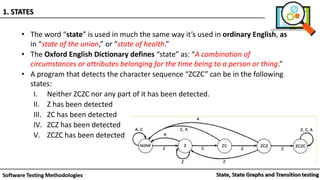
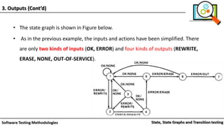
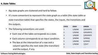
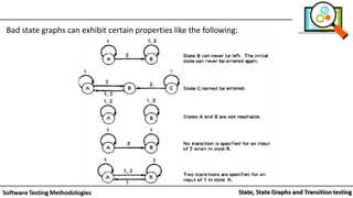


The document discusses finite state machines and state graphs. Some key points: - State graphs can model software behavior using states, inputs that cause transitions between states, and outputs. - States represent conditions or attributes of what is being modeled. Transitions between states are caused by inputs. - State graphs can be represented as state tables for clarity, with rows for each state and columns for each input. - Finite state machines are useful for software testing as they provide models of software structure and behavior to design tests against.