SlideShare a Scribd company logo
1 of 28
Download to read offline
MSc. Part II Sem III Embedded Systems
1
Embedded Systems Questions and Answers:
Q1. Differentiate between Embedded System and General Computing System.
Ans: 1. Embedded System:
• A system which is a combination of special purpose hardware and embedded OS for
executing a specific set of applications.
• May or may not contain an operating system for functioning.
• The firmware of the embedded system is pre-programmed and it is non-alterable by the
end users (There may be exceptions for system supporting OS Kernel image flashing
through special hardware settings.
• Application specific requirements (like performance, memory usage etc.) are the key
deciding factors.
• Highly tailored to take advantage of the power saving modes supported by the
hardware and the operating system.
• Execution behavior is deterministic for certain types of embedded systems like Hard
Real Time Systems.
2. General Computing System:
• A system which is a combination of a generic hardware and a General Purpose
Operating System for executing a variety of applications.
• Contains a General Purpose Operating System (GPOS).
• Applications are alterable (programmable) by the user. (It is possible for the end user to
re-install the operating system and also add or remove user applications.)
• Performance is the key deciding factor in the selection of the system.
• Less not at all tailored towards reduced operating power requirements options for
different levels of power management.
• Need to be deterministic in execution behavior.
Q2. Explain operational quality attributes of Embedded Systems.
Ans: The operational quality attributes represent the relevant quality attributes related to the
embedded system when it is in the operational mode or 'online' mode. The important quality
attributes coming under this category are:
1. Response: Response is a measure of quickness of the system. It gives an idea about
how fast system is tracking the changes in input variables.
2. Throughput: Throughput deals with the efficiency of a system. It can be defined as
the rate of production or operation of a defined process over a stated period of
time.
3. Reliability: Reliability is a measure of how much % we can be relied upon the proper
functioning of the system or what is the% susceptibility of the system to failures.
MSc. Part II Sem III Embedded Systems
2
4. Maintainability: Maintainability deals with support and maintenance to the end
user or client in case of technical issues and product failures or on the basis of a
routine system checkup.
5. Security: Confidentiality, Integrity, and Availability are the three major measures of
information security. Confidentiality deals with the protection of data and
application from unauthorized disclosure. Integrity deals with the protection of data
and application from unauthorized modification. Availability deals with protection of
data and application from unauthorized users. A very good example of the 'Security'
aspect in an embedded product is a Personal Digital Assistant (PDA).
6. Safety: Safety deals with the possible damages that can happen to the operators,
public and the environment due to the breakdown of an embedded system or due
to the emission of radioactive or hazardous materials from the embedded products.
Q3. Explain non-operational quality attributes of Embedded Systems.
Ans: The quality attributes that needs to be addressed for the product 'not' on the basis of
operational aspects are grouped under this category. The important quality attributes coming
under this category are:
1. Testability & Debug-ability: Testability deals with how easily one can test his/her
design, application and by which means he/she can test it. Debug-ability is a means of
debugging the product as such for figuring out the probable sources that create
unexpected behavior in the total system.
2. Evolvability: Evolvability refers to the ease with which the embedded product
(including firmware and hardware) can be modified to take advantage of new firmware
or hardware technologies.
3. Portability: Portability is a measure of 'system independence'. An embedded product is
said to be portable if the product is capable of functioning 'as such' in various
environments, target processors/controllers and embedded operating systems.
4. Time-to-Prototype and Market: Time-to-market is the time elapsed between the
conceptualization of a product and the time at which the product is ready for selling (for
commercial product) or use (for non-commercial products). Prototyping is an informal
kind of rapid product development in which the important features of the product
under consideration are developed.
5. Per Unit Cost and Revenue: Cost is a factor which is closely monitored by both end user
(those who buy the product) and product manufacturer (those who build the product).
Q4. Explain analysis and support phase in Embedded System development life cycle.
Ans: The classic Embedded Product Life Cycle Model contains the following phases:
1. Need.
2. Conceptualization.
3. Analysis.
4. Design.
5. Development and Testing.
6. Deployment.
MSc. Part II Sem III Embedded Systems
3
7. Support.
8. Upgrades.
9. Retirement/Disposal.
• Analysis: Requirements Analysis Phase starts immediately after the documents
submitted during the 'Conceptualization' phase is approved by the client/sponsor of the
project. Requirement analysis is performed to develop a detailed functional model of
the product under consideration. During the Requirements Analysis Phase, the product
is defined in detail with respect to the inputs, processes, outputs, and interfaces at a
functional level. Requirement Analysis phase gives emphasis on determining 'what
functions must be performed by the product' rather than how to perform those
functions.
The various activities performed during 'Requirement Analysis' phase are:
➢ Analysis and Documentation: The analysis-and documentation activity consolidates the
business needs of the product under development and analyses the purpose of the
product.
➢ Interface Definition and Documentation: The embedded product under consideration
may be a standalone product or it can be a part of a large distributed system.
➢ Defining Test Plan and Procedures: Identifies what kind of tests are to be performed
and what all should be covered in testing the product. Define-the test-procedures; test
setup and test environment.
• Support: The support phase deals with the operations and maintenance of the product
in a production environment. During this phase all aspects of operations and
maintenance of the product are covered and the product is scrutinized to ensure that it
meets the requirements put forward by the end user/client.
The various activities involved in the 'Support' phase are:
➢ Set up a Dedicated Support Wing: The availability of certain embedded products in
terms of product functioning in production environment is crucial and they may require
24x7 supports in case of product failure or malfunctioning.
➢ Identify Bugs and Areas of Improvement: None of the products are bug-free. Even if
the utmost care is taken in design, development and implementation of the product,
there can be bugs in it and the bugs reveal their real identity when the conditions are
favoring them .If the product faces an operating condition, the product behavior may
become unexpected and it is addressed with name 'Bug' by a software/product
engineer.
MSc. Part II Sem III Embedded Systems
4
Q5. Explain the Sequential Program Model for Seat Belt Warning System.
Ans: In the sequential programming Model, the functions or processing requirements are
executed in sequence. It is same as the conventional procedural programming. The execution of
functions in a sequential program model for the 'Seat Belt Warning' system is as follows:
Y
N
Y
No
Yes N No
Yes
Y
Ignition Key ON
Wait for 10 Seconds
Ignition
ON?
Seat Belt
ON?
Set Timer for 5 Seconds
Start Alarm
Ignition
ON?
Seat Belt
ON?
Time
Expired
Stop Alarm
End
MSc. Part II Sem III Embedded Systems
5
#define ON 1
#define OFF 0
#define YES 1
#define NO 0
void seat_belt_warn()
{
wait_10sec();
if(check_ignition_key()==ON)
{
if(check_seat_belt()==OFF)
{
set_timer(5);
start_alarm();
while((check_seat_belt()==OFF) && (check_ignition_key()==OFF) && (timer_expire()==NO));
stop_alarm();
}
}
}
Q6. Write a short note on Electronic Design Automation Tools.
Ans:
• Early embedded products were built around the old transistor and vacuum tube
technologies, where the designers built the PCB with their hands, oil paper, pencil, pen,
ruler and copper plates.
• Advances in computer technology and IT brought out highly sophisticated and
automated tools for PCB design and fabrication.
• The process of manual sketching the PCB has given way to software packages that gives
an automatic routing and layout for your product in a few seconds.
• These software packages are widely known as Electronic Design Automation (EDA)
tools and various manufactures offer these tools for different operating systems
(Windows, UNIX, Linux etc).
• EDA tool is a set of Computer Aided Design/Manufacturing (CAD/CAM) software
packages which helps in designing and manufacturing the electronic hardware like
integrated circuits, printed circuit board, etc.
• The key players of the EDA tool industry are Cadence, Protel, Altium, Cadsoft, Redac,
Merco, etc. OrCAD, Cadstar, Protel, Eagle, etc. are the popular EDA tool packages
available in the market for PCB design.
Q7. Write a short note on Device Drivers.
Ans:
• Device driver is a piece of software that acts as a bridge between the operating system
and the hardware.
• The device driver abstracts the hardware from user applications.
MSc. Part II Sem III Embedded Systems
6
• Device drivers are responsible for initiating and managing the communication with the
hardware peripherals. They are responsible for establishing the connectivity, initializing
the hardware (setting up various registers of the hardware device) and transferring
data.
• Device drivers which are part of the OS image are known as 'Built-in drivers' or 'On-
board drivers'. These drivers are loaded by the OS at the time of booting the device and
are always kept in the RAM. Drivers which need to be installed for accessing a device are
known as 'Installable drivers'. These drivers are loaded by the OS on a need basis.
• Drivers can run on either user space or kernel space. Drivers which run in user space are
known as user mode drivers and the drivers which run in kernel space are known as
kernel mode drivers. User mode drivers are safer than kernel mode drivers.
• Regardless of the OS types, a device driver implements the following:
a) Device (Hardware) Initialization and Interrupt configuration
b) Interrupt handling and processing
c) Client interfacing (Interfacing with user applications).
• The Device (Hardware initialization part of the driver deals with configuring the different
registers of the device (target hardware).
• The interrupt configuration part deals with configuring the interrupts that needs to be
associated with the hardware.
• The client interfacing implementation makes use of the Inter Process communication
mechanisms supported by the embedded OS for communicating and synchronizing with
user applications and drivers.
Q8. Explain High Level Language to Machine Language conversion process.
Ans:
• Any high level language (like C, C++ or Java) with a supported cross compiler for the
target processor can be used for embedded firmware development.
• The most commonly used high level language for embedded firmware application
development is 'C'.
• The various steps involved in the conversion of a program written in high level language
to corresponding binary file/machine language is as follows :
MSc. Part II Sem III Embedded Systems
7
Machine Code (Hex File)
• The program written in any of the high level language is saved with the corresponding
language extension (.c for C, .cpp for C++ etc).
• Any text editor like 'notepad' or 'WordPad' from Microsoft® or the text editor provided
by an Integrated Development (IDE) tool supporting the high level language in use can
be used for writing the program.
• Most of the high level languages support modular programming approach and hence
you can have multiple ·source files called modules written in corresponding high level
language.
• Translation of high level source code to executable object code is done by a cross-
compiler. The cross-compilers for different high level languages for the same target
processor are different.
• Without cross-compiler support a high level language cannot be used for embedded
firmware development.
Q9. How C/C++ is useful in embedded system programming. List the various advantages
of high level programming for embedded systems.
Ans:
• Any high level language (like C, C++ or Java) with a supported cross compiler for the
target processor can be used for embedded firmware development.
• The most commonly used high level language for embedded firmware application
development is 'C'.
• C is the well defined, easy to use high level language with extensive cross platform
development tool support.
• The program written in any of the high level language is saved with the corresponding
language extension (.c for C, .cpp for C++ etc).
➢ Advantages of high level programming for embedded systems:
1. Reduced Development Time: Developer requires less or little knowledge on the internal
hardware details and architecture of the target processor/controller. Bare minimal
Library Files
Object File 1
Object File 2
Linker/ Locator
Source File 1 (C/ C++ etc.)
(Module 1)
Module Cross- Compiler
Source File 2 (C/ C++ etc.)
(Module 2) Module Cross- Compiler
Object to Hex File
Converter
Absolute Object File
MSc. Part II Sem III Embedded Systems
8
knowledge of the memory organization and register details of the target processor in
use and syntax of the high level language are the only pre-requisites for high level
language based firmware development. Rest of the things will be taken care of by the
cross-compiler used for the high level language.
2. Developer Independency: The syntax used by most of the high level languages are
universal and a program written in the high level language can easily be understood by a
second person knowing the syntax of the language. Certain instructions may require
little knowledge of the target hardware details like register set, memory map etc.
3. Portability: Target applications written in high level languages are converted to target
processor/controller understandable format (machine codes) by a cross-compiler. An
application written in high level language for a particular target processor can easily be
converted to another target processor/controller specific application, with little or less
effort by simply re-compiling/little code modification followed by re-compiling the
application for the required target processor/controller, provided, the cross-compiler
has support for the processor/controller selected. This makes applications written in
high level language highly portable.
Q10. What are the open standards, frameworks and alliances present in the market?
Ans:
• The Open Alliances and standards body are aimed towards defining and formulating the
standards. Time to market is a critical factor in the sensational embedded market
segments. Open sources and frameworks reduce the time to market in product
development. The following are the popular strategic alliances, open source standards
and frameworks in the mobile handset industry.
1. Open Mobile Alliance (OMA): The Open Mobile Alliance (OMA) is a standards body for
developing open standards for mobile phone industry. The mission of OMA is to create
interoperable services across countries, operators and mobile terminals by acting as the
centre of the mobile service enabler specification work.
2. Open Handset Alliance (OHA): The Open Handset Alliance (OHA) is a business alliance
formed by various handset manufacturers (HTC, Samsung, LG, Motorola etc), chip
manufacturers (Intel, Nvidia, Qualcomm, etc.), platform-providers (Google, Wind River
Systems, etc.) and carriers (T-Mobile, China Mobile, Sprint Nextel, etc.) for developing
standards for mobile devices.
3. Android: Android is an open source software platform and operating system for mobile
devices. It was developed by Google Corporation. and retained by the Open Handset
Alliance (OH.A). The Android operating system is based on the Linux kernel. Google has
developed a set of Java libraries and developers can make use of these libraries for
application development in java.
4. Openmoko: Openmoko is a project for building open hardware and firmware (OS)
standards for a family of open source mobile phones. The target operating system under
MSc. Part II Sem III Embedded Systems
9
consideration by openmoko is Embedded Linux and it is known as Openmoko Linux. It
also supplies the hardware details (schematics and CAD drawings) of the phone as
reference design for developers. Developers can customize the software stack and
hardware to suit their product needs.
Q11. Differentiate between RISC and CISC processors.
Ans: 1. RISC processors:
• Less number of instructions.
• Instruction pipelining and increased execution speed.
• Orthogonal instruction set. (Allows each instruction to operate on any register and use
any addressing mode.)
• Operations are performed on registers only, the only memory operations are load and
store.
• A large number of registers are available.
• Programmer needs to write more code to execute a task since the instructions are
simpler ones.
• Single, fixed length instructions.
• Less silicon usage and pin count.
• With Harvard Architecture.
2. CISC processors:
• Greater number of instructions.
• Generally no instruction pipelining feature.
• Non-orthogonal instruction set. (All instructions are not allowed to operate on any
register and use any addressing mode. It is instruction specific.)
• Operations are performed on registers or memory, depending on the instruction.
• Limited number of general purpose registers.
• Instructions like macros in C language. A programmer can achieve the desired
functionality with a single instruction which in turn provided the effect of using more
simpler single instructions in RISC.
• Variable length instructions.
• More silicon usage since more additional decoder logic is required to implement the
complex instruction decoding.
• Can be Harvard or Von-Neumann Architecture.
Q12. Explain Little-endian and Big-endian systems.
Ans:
• Endianness specifies the order in which the data is stored in the memory by processor
operations in a multi byte system.
• Little-endian means the lower-order byte of the data is stored in memory at the lowest
address, and the higher-order byte at the highest address.
MSc. Part II Sem III Embedded Systems
10
Base Address+0 Ox20000 (Base Address)
Base Address+1 0x20001(Base Address+1)
Base Address+2 0x20002(Base Address+2)
Base Address+3 0x20003(Base Address+3)
• Big-endian means the higher-order byte of the data is stored in memory at the lowest
address, and the lower-order byte at the highest address.
Base Address+0 Ox20000 (Base Address)
Base Address+1 0x20001(Base Address+1)
Base Address+2 0x20002(Base Address+2)
Base Address+3 0x20003(Base Address+3)
Q13. Explain Von-Neumann and Harvard architecture.
Ans:
• The terms Harvard and Von-Neumann refers to the processor architecture design.
• Microprocessors/controllers based on the Von-Neumann architecture shares a single
common bus for fetching both instructions and data.
• Program instructions and data are stored in a common main memory.
• Von-Neumann architecture based processors/controllers first fetch an instruction and
then fetch the data to support the instruction from code memory.
• The two separate fetches slows down the controller's operation. Von-Neumann
architecture is also referred as Princeton architecture.
• Microprocessors/controllers based on the Harvard architecture will have separate data
bus and instruction bus.
• This allows the data transfer and program fetching to occur simultaneously on both
buses.
Byte 0
Byte 2
Byte 2
Byte 3
Byte 1
Byte 3
Byte 2
Byte 1
Byte 0
MSc. Part II Sem III Embedded Systems
11
• With Harvard architecture, the data memory can be read and written while the program
memory is being accessed.
• These separated data memory and code memory buses allow one instruction to execute
while the next instruction is fetched ("pre-fetching").
• The pre-fetch theoretically allows much faster execution than Von-Neumann
architecture.
• Since some additional hardware logic is required for the generation of control signals for
this type of operation it adds silicon complexity to the system.
Single Shared bus
Q14. Differentiate between Von-Neumann and Harvard architecture.
Ans: 1. Harvard Architecture:
• Separate buses for instruction and data fetching.
• Easier to pipeline, so high performance can be achieved.
• Comparatively high cost.
• No memory alignment problems.
• Since data memory and program memory are stored physically in different locations, no
chances for accidental corruption of program memory.
2. Von-Neumann Architecture:
• Single shared bus for instruction and data fetching.
• Low performance compared to Harvard Architecture.
• Cheaper.
• Allows self modifying codes.
• Since data memory and program memory are stored physically in the same chip,
chances for accidental corruption of program memory.
I/O CPU Memory
Program
Memory
CPU Data Memory
MSc. Part II Sem III Embedded Systems
12
Q15. Explain the fundamental issues in hardware and software co-design.
Ans: The hardware software co-design is a problem statement. The following illustrates the
fundamental issues in hardware software co-design.
1. Selecting the model: In hardware software co-design, models are used for capturing
and describing the system characteristics. A model is a formal system consisting of
objects and composition rules. It is hard to make a decision on which model should be
followed in a particular system design.
2. Selecting the Architecture: The architecture specifies how a system is going to
implement in terms of the number and types of different components and the
interconnection among them. Controller architecture, Datapath Architecture, Complex
Instruction Set Computing (CISC), Reduced Instruction Set Computing (RISC), Very Long
Instruction Word Computing (VLIW), Single Instruction Multiple Data (SIMD), Multiple
Instruction Multiple Data (MIMD), etc. are the commonly used architectures in system
design.
• Some of them fall into Application Specific Architecture Class (like controller
architecture), while others fall into either general purpose architecture class (CISC, RISC,
etc.) or Parallel processing class (like VLIW, SIMD, MIMD, etc.).
• The controller architecture implements the finite state machine model using a state
register and two combinational circuits.
• The Datapath architecture is best suited for implementing the data flow graph model
where the output is generated as a result of a set of predefined computations on the
input data.
• The Finite State Machine Datapath (FSMD) architecture combines the controller
architecture with datapath architecture. It implements a controller with datapath.
• The Complex Instruction Set Computing (CISC) architecture uses an instruction set
representing complex operations.
• The Very Long Instruction Word (VLIW) architecture implements multiple functional
units in the datapath.
• Parallel processing architecture implements multiple concurrent Processing Elements
(PEs) and each processing element may associate a datapath containing register and
local memory.
3. Selecting the Language: A programming language captures a 'Computational Model'
and maps it into architecture. A model can be captured using multiple programming
languages like C, C++, C#, Java, etc. for software implementations and languages like
VHDL, System C, Verilog, etc. for hardware implementations.
4. Partitioning System Requirements into hardware and software: From an
implementation perspective, it may be possible to implement the system requirements
in either hardware or software (firmware). Various hardware software trade-offs are
used for making a decision on the hardware-software partitioning.
MSc. Part II Sem III Embedded Systems
13
Q16. Explain embedded firmware design approach.
Ans: The firmware design approaches for embedded product is purely dependent on the
complexity of the functions to be performed, the speed of operation required, etc. Two basic
approaches are used for embedded firmware design. They are 'Conventional Procedural Based
Firmware Design' and 'Embedded Operating System (OS) Based Design'. The conventional
procedural based design is also known as 'Super Loop Model'.
1. The Super Loop Based Approach: The Super Loop based firmware development
approach is adopted for applications that are not time critical and where the response
time is not so important. It is very similar to a conventional procedural programming
where the code is executed task by task. The task listed at the top of the program code
is executed first and the tasks just below the top are executed after completing the first
task. The firmware execution flow for this will be:
1) Configure the common parameters and perform initialization for various hardware
components memory, registers, etc.
2) Start the first task and execute it
3) Execute the second task
4) Execute the next task
5) :
6) :
7) Execute the last defined task
8) Jump back to the first task and follow the same flow.
• The operational sequence can be visualized in terms of a 'C' program code:
void main()
{
Configurations();
Initializations();
while(1)
Task1();
Task2();
:
:
Taskn();
}
}
• Almost all tasks in embedded applications ate non-ending and are repeated infinitely
throughout the operation.
• This repetition is achieved by using an infinite loop. Here the while (1) { } loop. This
approach is also referred as· 'Super loop based Approach'.
• The 'Super loop based design' doesn't require an operating system, since there is no
need for scheduling which task is to be executed and assigning priority to each task.
MSc. Part II Sem III Embedded Systems
14
• In a super loop based design, the priorities are fixed and the order in which the tasks to
be executed are also fixed.
• A typical example of a 'Super loop based' product is an electronic video game toy
containing keypad and display unit.
• The 'Super loop based design' is simple and straight forward without any OS related
overheads.
• The major drawback of this approach is that any failure in any part of a single task will
affect the total system.
• Another major drawback of the 'Super loop' design approach is the lack of real
timeliness.
2. The Embedded Operating System (OS) Based Approach:
• The Operating System (OS) based approach contains operating systems, which can be
either a General Purpose Operating System (GPOS) or a Real Time Operating System
(RTOS) to host the user written application firmware. The General Purpose OS (GPOS)
based design is very similar to a conventional.
• PC based application development where the device contains an operating system.
• Real Time Operating System (RTOS) based design approach is employed in embedded
products demanding Real-time response. RTOS respond in a timely and predictable
manner to events.
• Real Time operating system contains a Real Time kernel responsible for performing pre-
emptive multitasking, scheduler for scheduling tasks, multiple threads, etc. A Real Time
Operating System (RTOS) allows flexible scheduling of system resources like the CPU and
memory and offers some way to communicate between tasks.
Q17. Write a note on Embedded OS trends.
Ans:
• The Embedded OS industry is also undergoing revolutionary changes to take advantage
of the potential offered by the trends in processor technologies.
• Most of the embedded OS’s are trying to bring the virtualization concept to the
embedded device industry by adopting the micro kernel architecture in place of the
monolithic architecture.
• In microkernel architecture, the kernel contains very limited and essential
features/services and rests of the features or services are installed as service and they
run at the user space.
• Another noticeable trend adopting by OS suppliers is the 'Device oriented' design similar
to the processor trends.
• In the olden days for building a device, OS were selected matching the device
requirements and then they were customized. Today OS suppliers are providing off-the-
shelf OS customized for the device.
• Microsoft Embedded OS product line is a typical example of this. Microsoft has a range
of OSs targeted for a group of device families like point of sale terminal, media player,
set top box, etc.
MSc. Part II Sem III Embedded Systems
15
• The Windows Mobile OS from Microsoft is specifically designed for mobile handsets.
Open source embedded OS (Mostly centered around Embedded Linux) are gaining
attention in the embedded market and the open source community is also offering off
the shelf OS customized for specific group/family of devices.
• The Ubuntu MID edition which is specifically designed for Mobile Internet Device (MID)
is a typical example for this. Since the processor technology is shifting the paradigm of
computing from single core to multicore processors, the OS suppliers are also forced to
change their strategies for supporting multicore processors.
• The latest version of the VxWorks RTOS is designed to support the latest market-leading
multicore processors.
Q18. What are different development language trends for embedded system
programming available?
Ans:
• There are two aspects of languages for embedded development. One is the system side
application (embedded device platform development) and the other one is the user
application development.
• The system side application is responsible for managing the embedded device,
interacting with low level hardware, scheduling and executing user applications,
memory management, etc. whereas the user application runs on top of the system
applications and requires the intervention of system application for performing system
resource access (Like hardware access, memory access, etc.).
• In Embedded terminology the system side applications are referred as 'Embedded
Firmware' and the user applications are known as 'Embedded Software'.
• The embedded firmware always comes as embedded into the program memory of the
device and it is unalterable by the end user.
• Embedded software comes as either embedded with the firmware or user can install the
software applications later on the device.
• The following sections illustrate the role of Java and Microsoft .NET framework
supported languages for embedded development.
1. Java for Embedded Development:
➢ Java being considered as the popular language for enterprise applications due to its
platform independent implementations.
➢ It is not popular in embedded application development due to its inherent shortcomings
in real time system development support.
➢ In a basic java development, the java code is compiled by a java class compiler to
platform independent code called java byte code.
➢ The java byte code is converted into processor specific object code by a utility called
Java Virtual Machine (NM).
MSc. Part II Sem III Embedded Systems
16
➢ JVM abstracts the processor dependency from Java applications. JVM performs the
operation of converting the byte code into the processor specific machine code
implementations.
➢ JVM can be implemented as either a piece of software code or hardware unit.
➢ The ARM processor implements hardware NM called jazelle for supporting java.
➢ Implementation of Java applications in an embedded device with Operating System.
➢ JVM interprets the byte code and thereby greatly affects the speed of execution.
➢ Another technique called Just In Time (JIT) compiler speeds up the Java program
execution by caching all the previously interpreted byte code.
➢ The limitations of standard Java in embedded application development are:
1. The interpreted version of Java is quite slower and is not meeting the real-time
requirement demanding by most embedded systems (For real-time applications)
2. The garbage collector of Java is non-deterministic in execution behavior. It is not
acceptable for a hard real-time system.
3. Processors which don't have a built-in JVM support or off-the-shelf software JVM,
require the JVM ported for the processor architecture.
4. The resource access (Hardware registers, memory, etc.) supported by Java is limited.
5. The runtime memory requirement for JVM and Java class libraries or JIT is a bit high
and embedded systems which are constrained on memory cannot afford this.
➢ Java provides an interface named Java Native Interface (JNI), which can be used for
invoking the functions written in other languages like C and Assembly. The JNI feature of
Java can be explored for implementing system software like, user mode device drivers
which has access to the JVM.
➢ Java Platform Micro Edition (Java ME), which was known as J2ME earlier, is a
customized Java version specifically designed for 'Embedded application software'
development for devices like mobile phones, PDAs, Set Top Boxes, printers, etc. Java ME
applications are portable across devices.
2. .NET CF for Embedded Development:
➢ .NET is a framework for application development for desktop Windows Operating
Systems) from Microsoft.
Java Applications
Java Virtual Machine (JVM)
Embedded OS (RTOS/GPOS)
Embedded Hardware
MSc. Part II Sem III Embedded Systems
17
➢ It is a collection of pre-coded libraries and it acts as the run time component for .NET
supported languages (C++, C#, VB, J#, etc.). It contains class libraries for User Interface,
database connectivity, network connectivity, image editing, ·cryptography etc.
➢ The runtime environment of .NET is known as Common Language Runtime (CLR). The
CLR resembles JVM in operation. It abstracts the target processor from application
programmer.
➢ Like JVM, CLR also provides memory management (garbage collection), exception
handling, etc. The CLR provides a language neutral platform for application
development and execution. Applications written in .NET supported languages are
compiled to a platform neutral intermediate language called Common Intermediate
Language (CIL).
➢ For actual execution, the CIL is converted to the target processor specific machine code
by the Common Language Runtime (CLR).
➢ The .NET framework is targeted for enterprise application development for desktop
systems. The .NET framework consumes significant amount of memory. The .NET
framework in embedded application development is not a viable choice due to its
memory requirement.
➢ .NET based Embedded Application Development:
Target processor specific machine code
Q19. Elaborate processor trends in embedded system.
Ans: The following are the key processor architecture/trends in embedded development.
.NET Supported languages
(C++, C#, VB etc.)
Compiler
Common Interface Language
(CIL)
Common Language Runtime
(CLR)
MSc. Part II Sem III Embedded Systems
18
1. System on Chip (Soc):
• A System on Chip (SoC) makes a system on a single chip.
• The System on Chip technology places multiple function 'system’s on a single chip.
• SoCs changed the concept of embedded processor from general purpose design to
device specific design.
• Nowadays SoCs are available for diverse application needs like Set Top Boxes, Portable
media players, PD As, etc.
• iMX3 1 SoC from free scale semiconductor is a typical example for SoC targeted for
multimedia applications.
• By integrating multiple functions into a single chip, SoCs greatly save the board space in
embedded hardware development and thereby leads to the concept of miniaturization.
SoCs are also cost effective.
2. Multicore Processors/Chiplevel Multi Processor (CMP):
• One way of achieving increased performance is to increase the operating clock
frequency.
• Multicore processors incorporate multiple processor cores on the same chip and works
on the same clock frequency supplied to the chip.
• Based on the number of cores, the processors are known as dual core (2 cores), tri core
(3 cores), quad core (4 cores), etc.
• Multicore processors implement multiprocessing. Each core of the CMP implements
pipelining, multithreading and superscalar execution.
3. Reconfigurable Processors:
• Reconfigurable processor is a microprocessor/controller with reconfigurable hardware
features.
• They contain an array of Programming Elements (PE) along with a microprocessor
(Typically a RISC processor).
• The PE can be either a computational engine or a memory element. The hardware
feature of the reconfigurable processor can be changed statically or dynamically.
• The dynamic changing of hardware configuration brings the advantage of making the
chip adaptable to the firmware running on the processor.
• Depending on the situational-need, there configurable processor can entirely change
their functionality to adapt to the new requirements.
Q20. What is EDLC? What are the objectives of the EDLC?
Ans: EDLC is essential for understanding the scope and complexity of the work involved in any
embedded product development.
MSc. Part II Sem III Embedded Systems
19
EDLC defines the interaction and activities among various groups of a product development
sector including project management, system design and development, system testing, release
management and quality assurance.
Objectives of the EDLC: EDLC has three primary objectives.
• Ensure that high quality products are delivered to end user.
• Risk minimization and defect prevention in product development through project
management.
• Maximize the productivity.
1. Ensuring High Quality for Products:
• The primary definition of quality in any embedded product development is the Return
on Investment (ROI) achieved by the product.
• The expenses incurred for developing the product may fall in any of the categories;
initial investment, developer recruiting, training, or any other infrastructure
requirement related.
• EDLC must ensure that the development of the product has taken account of all the
qualitative attributes of the embedded system.
2. Risk Minimization and Defect Prevention through Management:
• There are projects in embedded product development which requires 'loose' or 'tight'
project management.
• Projects which are complex and requires timeliness should have a dedicated and skilled
project management part and hence they are said to be "tightly" bounded to project
management.
• Project management is essential for predictability, co-ordination and risk minimization'.
• Whenever a product development request comes, an estimate on the duration of the
development and deployment activity should be given to the end user/client.
• Resource (Developer) allocation is another aspect of predictability in management.
Resource allocations like how many resources should work for this project for how many
days, how many resources are critical with respect to the work handling by them and
how many backups required for the resources to 9vercome a critical situation where a
resource is not available (Risk minimization).
• Resource allocation is critical and it is having a direct impact on investment.
• The communication aspect of the project management deals with co-ordination and
interaction among resources and client from which the request for the product
development aroused.
• Project management adds an extra cost on the budget but it is essential for ensuring the
development process is going in the right direction and the schedules of the
development activity are meeting.
MSc. Part II Sem III Embedded Systems
20
3. Increased Productivity:
• Productivity is a measure of efficiency as well as Return on Investment (ROI). One aspect
of productivity covers how many resources are utilized to build the product, how much
investment required, how much time is taken for developing the product, etc.
• Productivity in terms of Returns is said to be increased, if the product is capable of
yielding maximum returns with reduced investment.
• Another important factor which can help in increased productivity is "re-usable effort".
This will definitely increase the productivity by reducing the development effort.
• Another advised method for increasing the productivity is by using resources with
specific skill sets which matches the exact requirement of the entire or part of the
product.
• COTS component is a ready to use component and you can use the same as plug-in
modules in your product.
Q21. Give brief idea of different phases of EDLC.
Ans: The life cycle of a product development is commonly referred to as models. Model defines
the various phases involved in the life cycle. The number of phases involved in a model may
vary according to the complexity of the product under consideration. A typical simple product
contains five minimal phases namely: 'Requirement Analysis', 'Design', 'Development and Test',
'Deployment' and 'Maintenance'.
The classic Embedded Product Life Cycle Model contains the phases: 'Need',
'Conceptualization', 'Analysis', ' Design', 'Development and Testing', 'Deployment', 'Support',
'Upgrades' and 'Retirement/ Disposal'.
The number of phases involved in the EDLC model depends on the complexity of the product.
The flowing are the phases of the classic EDLC model:
MSc. Part II Sem III Embedded Systems
21
Retirement Need Conceptualization
Upgrades Analysis
Support Design
Deployment Deployment and Testing
1. Need: Any embedded product evolves as an output of a 'Need'. The need may come
from an individual or from the public or from a company. Need' should be articulated to
initiate the Product Development Life Cycle and based on the need for the product, a
'Statement of Need' or 'Concept Proposal' is prepared. The 'Concept Proposal' must be
reviewed by the senior management and funding agency and should get necessary
approval. Once the proposal gets approval, it goes to a product development team,
which can either be an organization from which the need arise or a third party product
development/service company. The product development need can be visualized in any
one of the following three needs:
• New or Custom Product Development: The need for a product which does not exist in
the market or a product which acts as competitor to an existing product in the current
market will lead to the development of a completely new product. The product can be a
commercial requirement or an individual requirement or a specific organization’s
requirement.
• Product Re-engineering: The embedded product market is dynamic and competitive.
Reengineering a product is the process of making changes in an existing product design
EDLC
MSc. Part II Sem III Embedded Systems
22
and launching it as a new version. It is generally termed as product upgrade. Re-
engineering an existing product comes as a result of the following needs.
➢ Change in Business requirements.
➢ User Interface Enhancements.
➢ Technology Upgrades.
• Product Maintenance: Product maintenance 'need' deals with providing technical
support to the end user for an existing product in the market. The maintenance request
may come as a result of product non-functioning or failure. Product maintenance is
generally classified into two categories: Corrective maintenance and Preventive
maintenance. Corrective maintenance deals with making corrective actions following a
failure or non-functioning. The failure can occur due to damages or nonfunctioning of
components/parts of the product and the corrective maintenance replaces them to
make the product functional again. Preventive maintenance is the scheduled
maintenance to avoid the failure or non-functioning of the product.
2. Conceptualization: Conceptualization is the 'Product Concept Development Phase' and
it begins immediately after a Concept Proposal is formally approved. Conceptualization
phase defines the scope of the concept, performs cost benefit analysis and feasibility
study and prepares project management and risk management plans. Conceptualization
can be viewed as a phase shaping the "Need" of an end-user or convincing the end user,
whether it is a feasible product and how this product can be realized. The
'Conceptualization' phase involves two types of activities, namely; 'Planning Activity' and
'Analysis and Study Activity'. The Analysis and Study Activities are performed to
understand the opportunity of the product in the market. The following are the
important 'Analysis and Study activities' performed during 'Conceptualization Phase'.
• Feasibility Study: Feasibility study examines the need for the product carefully and
suggests one or more possible solutions to build the need as a product along with
alternatives. Feasibility study analyses the Technical as well as financial feasibility of the
product under consideration.
• Cost Benefit Analysis (CEA): The Cost Benefit Analysis (CBA) is a means of identifying,
revealing and assessing the total development cost and the profit expected from the
product.
• Product Scope: Product scope deals with what is in scope for the product and what is
not in scope for the product.
• Planning Activities: The planning activity covers various plans required for the product
development, like the plan and schedule for executing the next phases following
conceptualization, Resource Planning and Risk Management Plans.
3. Analysis: Requirements Analysis Phase starts immediately after the documents
submitted during the 'Conceptualization' phase is approved by the client/sponsor of the
project. Requirement analysis is performed to develop a detailed functional model of
the product under consideration. During the Requirements Analysis Phase, the product
is defined in detail with respect to the inputs, processes, outputs, and interfaces at a
MSc. Part II Sem III Embedded Systems
23
functional level. Requirement Analysis phase gives emphasis on determining 'what
functions must be performed by the product' rather than how to perform those
functions.
The various activities performed during 'Requirement Analysis' phase are:
➢ Analysis and Documentation: The analysis-and documentation activity consolidates the
business needs of the product under development and analyses the purpose of the
product.
➢ Interface Definition and Documentation: The embedded product under consideration
may be a standalone product or it can be a part of a large distributed system.
➢ Defining Test Plan and Procedures: Identifies what kind of tests are to be performed
and what all should be covered in testing the product. Define-the test-procedures; test
setup and test environment.
4. Design: Product 'Design phase' deals with the entire design of the product taking the
requirements into consideration and it focuses on 'how' the required functionalities can
be delivered to the product. The design phase identifies the application environment
and creates an overall architecture for the product. Product design starts with
'Preliminary Design/High Level Design'. Preliminary design establishes the top-level
architecture for the product, lists out the various functional blocks required for the
product, and defines the inputs and outputs for each functional block. On completion,
the 'Preliminary Design Document (PDD) is sent for review to the end-user/client. If the
end-user agrees on the preliminary design, the product design team can take the work
to the next level - 'Detailed Design'. Detailed design generates a detailed architecture,
identifies and lists out the various components for each functional block, the inter
connection among various functional blocks, the control algorithm requirements, etc.
The 'Detailed Design' also needs to be reviewed and get approved by the end
user/customer. The other activities performed during the design phase are 'Design of
Operations and maintenance manual' and 'Design of Training materials'. The operations
manual is necessary for educating the end user on 'how to operate the product' and the
maintenance manual is essential for providing information on how to handle the
product in situations like non-functioning, failure, etc.
Preliminary Design Detailed Design Detailed Design
Document
Preliminary Design
Document
Operations manual
design
Maintenance
manual design
Product training
material design
MSc. Part II Sem III Embedded Systems
24
5. Development and Testing: The 'Development Phase' transforms the design into a
realizable product. For this the detailed specifications generated during the design
phase are translated into hardware and firmware. During development phase, the
installation and setting up of various development tools is performed and the product
hardware and firmware is developed using different tools and associated production
setup. The development activities can be partitioned into embedded hardware
development, embedded firmware development and product enclosure development.
Embedded hardware development refers to the development of the component
placement platform – PCB using CAD tools and its fabrication using CAM Tools.
Embedded firmware development is performed using the embedded firmware
development tools.
The testing phase can be divided into independent testing of firmware and hardware
(Unit Testing), testing of the product after integrating the firmware and hardware
(Integration Testing), testing of the whole system on a functionality and non-
functionality basis (System Testing) and testing of the product against all acceptance
criteria mentioned by the client/end user for each functionality (User Acceptance
Testing). The Unit testing deals with testing the embedded hardware and its associated
modules, the different modules of the firmware for their functionality independently.
Depending on the product complexity, rest of the tests can be considered as the
activities performed in the 'Testing phase' of the product.
The Integration testing ensures that the functionality which is tested working properly in
an independent mode remains working properly in an integrated product (Hardware +
Firmware).
The system testing follows the Integration testing and it is a set of various tests for
functional and non-functional requirements verification. System testing is a kind of black
box testing, which doesn't require any knowledge on the inner design logic or code for
the product.
User acceptance test or simply Acceptance testing is the product evaluation performed
by the customer as a condition of the product purchase.
6. Deployment: Deployment is the process of launching the first fully functional model of
the product in the market or handing over the fully functional initial model to an end
user/client is also known as First Customer Shipping (FCS).
The 'Deployment Phase' is initiated after the system is tested and accepted by the end
user. The important tasks performed during the Deployment Phase are as follows:
• Notification of Product Deployment: Whenever the product is ready to launch in the
market, the launching ceremony details should be communicated to the stake holders
and to the public if it is a commercial product. The notifications can be sent out through
e-mail, media, etc. mentioning the following:
➢ Deployment Schedule (Date Time and Venue)
➢ Brief description about the product
➢ Targeted end users
MSc. Part II Sem III Embedded Systems
25
➢ Extra features supported with respect to an existing product.
➢ Product support information including the support person name, contact number,
contact mail ID etc.
• Execution of Training Plan Proper training should be given to the end user to get them
acquainted with the new product. Before launching the product, conduct proper
training as per the training plan developed during the earlier phases. Proper training will
help in reducing the possible damages to the product as well as the operating person,
including personal injuries and product mal-functioning due to inappropriate usage.
User manual will help in understanding the product, its usage and accessing its
functionalities to certain extend.
• Product Installation Install the product as per the installation document to ensure that
it is fully functional. As a typical example take the case of a newly purchased mobile
handset. The user manual accompanying it will tell you clearly how to install the battery,
how to charge the battery, how many hours the battery needs to be charged, how the
handset can be switched on/off, etc.
• Product post-Implementation Review: Once the product is launched in the market,
conduct a post-implementation review to determine the success of the product. The
ultimate aim behind post-implementation review is to document the problems faced
during installation and the solutions adopted to overcome them which will act as a
reference document for future product development. It also helps in understanding the
customer needs and the expectations of the customer on the next version of the
product.
7. Support: The support phase deals with the operations and maintenance of the product
in a production environment. During this phase all aspects of operations and
maintenance of the product are covered and the product is scrutinized to ensure that it
meets the requirements put forward by the end user/client.
The various activities involved in the 'Support' phase are:
• Set up a Dedicated Support Wing: The availability of certain embedded products in
terms of product functioning in production environment is crucial and they may require
24x7 supports in case of product failure or malfunctioning.
• Identify Bugs and Areas of Improvement: None of the products are bug-free. Even if
the utmost care is taken in design, development and implementation of the product,
there can be bugs in it and the bugs reveal their real identity when the conditions are
favoring them .If the product faces an operating condition, the product behavior may
become unexpected and it is addressed with name 'Bug' by a software/product
engineer.
MSc. Part II Sem III Embedded Systems
26
8. Upgrades: The upgrade phase of product development deals with the development of
up- , grades (new versions) for the product which is already present in the market.
Product upgrade results as an output of major bug fixes or feature enhancement
requirements from the end user. During the upgrade phase the system is subject to
design modification to fix the major bugs reported or to incorporate the new feature
addition requirements aroused during the support phase. For embedded products, the
upgrades may be for the product resident firmware or for the hardware embedding the
firmware.
The product resident firmware will· have a version number which starts with version 1.0
and after each firmware modification or bug fix, the firmware version is changed
accordingly. Version numbering is essential for backward traceability. Releasing of
upgrades is managed through release management. Certain feature enhancements and
bug fixes require hardware modification and they are generally termed as hardware
upgrades. Firmware also needs to be modified according to the hardware
enhancements. The upgraded product appears in the market with the same name as
that of the initial product with a different version number or with a different name.
9. Retirement/Disposal: The retirement/disposition phase is the final phase in a product
development life cycle where the product is declared as obsolete and discontinued from
the market. The disposition of a product is essential due to the following reasons.
• Rapid technology advancement.
• Increased user needs.
The disposal/ retirement of a product is a gradual process: When the product
manufacture realizes that there is another powerful technology or component available
in the market which is most suitable for the production of the current product, they will
announce the current product as obsolete and the newer version/upgrade of the same
is going to be released soon.
Some products may get a very long 'Life Time' in the market, beginning from the launch
phase to the retirement phase and during this time the product will get reasonably good
amount of maturity and stability.
Q22. Explain Finite State Machine Model for automatic Tea/Coffee vending machine.
Ans: In its simplest representation, it contains four states namely; 'Wait for coin' 'Wait for User
Input', 'Dispense Tea' and 'Dispense Coffee'. The event 'Insert Coin' (5 rupee coin insertion),
transitions the state to 'Wait for User Input’. The system stays in this state until a user input is
received from the buttons 'Cancel', 'Tea' or '.Coffee' (Tea and Coffee are the drink select
button). If the event triggered in 'Wait State' is 'Cancel' button press, the coin is pushed out and
the state transitions to 'Wait for Coin If the event received in the 'Wait State' is either 'Tea'
button press, or 'Coffee' button press, the state changes to 'Dispense Tea' and 'Dispense Coffee'
respectively. Once the coffee/tea vending is over, the respective states transitions back to the
'Wait for Coin' state. A few modifications like adding a timeout for the 'Wait State' (Currently
the 'Wait State' is infinite; it can be re-designed to a timeout based 'Wait State'. If no user input
MSc. Part II Sem III Embedded Systems
27
is received within the timeout period, the coin is returned back and the state automatically
transitions to 'Wait for Coin' on the timeout event) and capturing another events like, 'Water
not available', 'Tea/Coffee Mix not available' and changing the state to an 'Error State' can be
added to enhance this design.
Event: Insert Coin
Action: OK
Event: Cancel Button
Action: Coin Out
State
A
State
B
State
C
State
D
Event: Coffee
Dispensed
Action: Done
Action: Done
Event: Tea Dispensed
Event: Tea
Button Press
Action: Dispense
Tea
Event: Coffee Button
Press
Action: Dispense
Coffee
MSc. Part II Sem III Embedded Systems
28
Q23. Explain Re-entrant function.
Ans:
• Functions which can be shared safely with several processes concurrently are called re-entrant
functions. When a re-entrant function is executing, another process can interrupt the execution
and can execute the same re-entrant function. The "another process" referred here can be a
thread in a multithreaded application or can be an Interrupt Service Routine (ISR).
• Re-entrant function is also referred as 'pure' function. Embedded applications extensively make
use of re-entrant functions. Interrupt Service Routine (ISR) in Super loop based firmware
systems and threads in RTOS based systems can change the program's control flow to alter the
current context at any time.
• When an interrupt is asserted, the current operation is put on hold and the control is
transferred to another function or task (ISR).
• In embedded applications, a function/subroutine is considered re-entrant if and only if it
satisfies the following criteria.
1. The function should not hold static data over successive calls, or return a pointer to static data.
2. All shared variables within the function are used in an atomic way.
3. The function does not call any other non-reentrant functions within it.
4. The function does not make use of any hardware in a non-atomic way.
Rule# 1: deals with variable usage and function return value for a reentrant function.
Rule# 2: deals with 'atomic' operations.
Rule #3: If a re-entrant function calls another function which is non-reentrant, it may create
potential damages due to the unexpected modification of shared variables if any.
Rule# 4: deals with the atomic way of accessing hardware devices. The term 'atomic' in hardware
access refers to the number of steps involved in accessing a specific register of a hardware device.

More Related Content

What's hot

What's hot (20)

Ch8.testing
Ch8.testingCh8.testing
Ch8.testing
 
Software evolution -- Good practices
Software evolution -- Good practicesSoftware evolution -- Good practices
Software evolution -- Good practices
 
SE2_Lec 22_Software Configuration Management
SE2_Lec 22_Software Configuration ManagementSE2_Lec 22_Software Configuration Management
SE2_Lec 22_Software Configuration Management
 
Software Quality Assurance
Software Quality AssuranceSoftware Quality Assurance
Software Quality Assurance
 
Ch25-Software Engineering 9
Ch25-Software Engineering 9Ch25-Software Engineering 9
Ch25-Software Engineering 9
 
Configuration management24
Configuration management24Configuration management24
Configuration management24
 
Socio technical system
Socio technical systemSocio technical system
Socio technical system
 
Intro softwareeng
Intro softwareengIntro softwareeng
Intro softwareeng
 
Quality attributes in software architecture
Quality attributes in software architectureQuality attributes in software architecture
Quality attributes in software architecture
 
Software Maintenance
Software MaintenanceSoftware Maintenance
Software Maintenance
 
SE18_Lec 04_Requirements Analysis and Specification
SE18_Lec 04_Requirements Analysis and SpecificationSE18_Lec 04_Requirements Analysis and Specification
SE18_Lec 04_Requirements Analysis and Specification
 
Software maintenance
Software maintenanceSoftware maintenance
Software maintenance
 
Software evolution evangelisation
Software evolution evangelisationSoftware evolution evangelisation
Software evolution evangelisation
 
Software Evolution and Maintenance Models
Software Evolution and Maintenance ModelsSoftware Evolution and Maintenance Models
Software Evolution and Maintenance Models
 
Software maintenance
Software maintenance Software maintenance
Software maintenance
 
Sw testing
Sw testingSw testing
Sw testing
 
SDLC Model
SDLC  ModelSDLC  Model
SDLC Model
 
Ch10 dependable systems
Ch10 dependable systemsCh10 dependable systems
Ch10 dependable systems
 
Ch3. agile sw dev
Ch3. agile sw devCh3. agile sw dev
Ch3. agile sw dev
 
Software evolution and maintenance
Software evolution and maintenanceSoftware evolution and maintenance
Software evolution and maintenance
 

Similar to Embedded Systems Q and A M.Sc.(IT) PART II SEM III

UNIT 1C CHARACTERISTICS _ QUALITY ATT OF ES.pptx
UNIT 1C CHARACTERISTICS _ QUALITY ATT OF ES.pptxUNIT 1C CHARACTERISTICS _ QUALITY ATT OF ES.pptx
UNIT 1C CHARACTERISTICS _ QUALITY ATT OF ES.pptxSKILL2021
 
Fundamentals of software development
Fundamentals of software developmentFundamentals of software development
Fundamentals of software developmentPratik Devmurari
 
University roll (Sub code).pptx
University roll (Sub code).pptxUniversity roll (Sub code).pptx
University roll (Sub code).pptxSKILL2021
 
Softweare Engieering
Softweare Engieering Softweare Engieering
Softweare Engieering Huda Alameen
 
Quality attributes of Embedded Systems
Quality attributes of Embedded Systems Quality attributes of Embedded Systems
Quality attributes of Embedded Systems VijayKumar5738
 
3Audit Software & Tools.pptx
3Audit Software & Tools.pptx3Audit Software & Tools.pptx
3Audit Software & Tools.pptxjack952975
 
Software Development Life Cycle Testingtypes
Software Development Life Cycle TestingtypesSoftware Development Life Cycle Testingtypes
Software Development Life Cycle Testingtypesvladimir zaremba
 
VAL-210-Computer-Validati-Plan-sample.pdf
VAL-210-Computer-Validati-Plan-sample.pdfVAL-210-Computer-Validati-Plan-sample.pdf
VAL-210-Computer-Validati-Plan-sample.pdfSamehMostafa33
 
Analysis concepts and principles
Analysis concepts and principlesAnalysis concepts and principles
Analysis concepts and principlessaurabhshertukde
 
Week_01-Intro to Software Engineering-1.ppt
Week_01-Intro to Software Engineering-1.pptWeek_01-Intro to Software Engineering-1.ppt
Week_01-Intro to Software Engineering-1.ppt23017156038
 
1. object oriented concepts & principles
1. object oriented concepts & principles 1. object oriented concepts & principles
1. object oriented concepts & principles poonam bora
 
Attributes of 'well - engineered' software product
Attributes of 'well - engineered' software productAttributes of 'well - engineered' software product
Attributes of 'well - engineered' software productandyr91
 
A CASE Lab Report - Project File on "ATM - Banking System"
A CASE Lab Report - Project File on  "ATM - Banking System"A CASE Lab Report - Project File on  "ATM - Banking System"
A CASE Lab Report - Project File on "ATM - Banking System"joyousbharat
 
Software engineering introduction
Software engineering introductionSoftware engineering introduction
Software engineering introductionVishal Singh
 
Software Engineering Important Short Question for Exams
Software Engineering Important Short Question for ExamsSoftware Engineering Important Short Question for Exams
Software Engineering Important Short Question for ExamsMuhammadTalha436
 

Similar to Embedded Systems Q and A M.Sc.(IT) PART II SEM III (20)

UNIT 1C CHARACTERISTICS _ QUALITY ATT OF ES.pptx
UNIT 1C CHARACTERISTICS _ QUALITY ATT OF ES.pptxUNIT 1C CHARACTERISTICS _ QUALITY ATT OF ES.pptx
UNIT 1C CHARACTERISTICS _ QUALITY ATT OF ES.pptx
 
Fundamentals of software development
Fundamentals of software developmentFundamentals of software development
Fundamentals of software development
 
University roll (Sub code).pptx
University roll (Sub code).pptxUniversity roll (Sub code).pptx
University roll (Sub code).pptx
 
Softweare Engieering
Softweare Engieering Softweare Engieering
Softweare Engieering
 
Se lec 3
Se lec 3Se lec 3
Se lec 3
 
Quality attributes of Embedded Systems
Quality attributes of Embedded Systems Quality attributes of Embedded Systems
Quality attributes of Embedded Systems
 
3Audit Software & Tools.pptx
3Audit Software & Tools.pptx3Audit Software & Tools.pptx
3Audit Software & Tools.pptx
 
Software Development Life Cycle Testingtypes
Software Development Life Cycle TestingtypesSoftware Development Life Cycle Testingtypes
Software Development Life Cycle Testingtypes
 
VAL-210-Computer-Validati-Plan-sample.pdf
VAL-210-Computer-Validati-Plan-sample.pdfVAL-210-Computer-Validati-Plan-sample.pdf
VAL-210-Computer-Validati-Plan-sample.pdf
 
SE
SESE
SE
 
Analysis concepts and principles
Analysis concepts and principlesAnalysis concepts and principles
Analysis concepts and principles
 
Week_01-Intro to Software Engineering-1.ppt
Week_01-Intro to Software Engineering-1.pptWeek_01-Intro to Software Engineering-1.ppt
Week_01-Intro to Software Engineering-1.ppt
 
1. object oriented concepts & principles
1. object oriented concepts & principles 1. object oriented concepts & principles
1. object oriented concepts & principles
 
Attributes of 'well - engineered' software product
Attributes of 'well - engineered' software productAttributes of 'well - engineered' software product
Attributes of 'well - engineered' software product
 
A CASE Lab Report - Project File on "ATM - Banking System"
A CASE Lab Report - Project File on  "ATM - Banking System"A CASE Lab Report - Project File on  "ATM - Banking System"
A CASE Lab Report - Project File on "ATM - Banking System"
 
Software engineering introduction
Software engineering introductionSoftware engineering introduction
Software engineering introduction
 
Software Engineering Important Short Question for Exams
Software Engineering Important Short Question for ExamsSoftware Engineering Important Short Question for Exams
Software Engineering Important Short Question for Exams
 
software engineering
software engineering software engineering
software engineering
 
SE Lecture 1.ppt
SE Lecture 1.pptSE Lecture 1.ppt
SE Lecture 1.ppt
 
SE Lecture 1.ppt
SE Lecture 1.pptSE Lecture 1.ppt
SE Lecture 1.ppt
 

More from Ni

Cryptography summary
Cryptography summaryCryptography summary
Cryptography summaryNi
 
INFORMATION SECURITY MANAGEMENT
INFORMATION SECURITY MANAGEMENTINFORMATION SECURITY MANAGEMENT
INFORMATION SECURITY MANAGEMENTNi
 
INFORMATION SECURITY: THREATS AND SOLUTIONS.
INFORMATION SECURITY: THREATS AND SOLUTIONS.INFORMATION SECURITY: THREATS AND SOLUTIONS.
INFORMATION SECURITY: THREATS AND SOLUTIONS.Ni
 
India's social challenge
India's social challengeIndia's social challenge
India's social challengeNi
 
ADOBE DREAMWEAVER
ADOBE DREAMWEAVERADOBE DREAMWEAVER
ADOBE DREAMWEAVERNi
 
PYTHON NOTES
PYTHON NOTESPYTHON NOTES
PYTHON NOTESNi
 
Code coverage analysis in testing
Code coverage analysis in testingCode coverage analysis in testing
Code coverage analysis in testingNi
 
ASP.NET MVC.
ASP.NET MVC.ASP.NET MVC.
ASP.NET MVC.Ni
 
LASER
LASERLASER
LASERNi
 
Java communication api
Java communication apiJava communication api
Java communication apiNi
 
Library management system
Library management systemLibrary management system
Library management systemNi
 
Impact of social networking sites- advantages and disadvantages
Impact of social networking sites- advantages and disadvantagesImpact of social networking sites- advantages and disadvantages
Impact of social networking sites- advantages and disadvantagesNi
 
Ppt on nan
Ppt on nanPpt on nan
Ppt on nanNi
 

More from Ni (13)

Cryptography summary
Cryptography summaryCryptography summary
Cryptography summary
 
INFORMATION SECURITY MANAGEMENT
INFORMATION SECURITY MANAGEMENTINFORMATION SECURITY MANAGEMENT
INFORMATION SECURITY MANAGEMENT
 
INFORMATION SECURITY: THREATS AND SOLUTIONS.
INFORMATION SECURITY: THREATS AND SOLUTIONS.INFORMATION SECURITY: THREATS AND SOLUTIONS.
INFORMATION SECURITY: THREATS AND SOLUTIONS.
 
India's social challenge
India's social challengeIndia's social challenge
India's social challenge
 
ADOBE DREAMWEAVER
ADOBE DREAMWEAVERADOBE DREAMWEAVER
ADOBE DREAMWEAVER
 
PYTHON NOTES
PYTHON NOTESPYTHON NOTES
PYTHON NOTES
 
Code coverage analysis in testing
Code coverage analysis in testingCode coverage analysis in testing
Code coverage analysis in testing
 
ASP.NET MVC.
ASP.NET MVC.ASP.NET MVC.
ASP.NET MVC.
 
LASER
LASERLASER
LASER
 
Java communication api
Java communication apiJava communication api
Java communication api
 
Library management system
Library management systemLibrary management system
Library management system
 
Impact of social networking sites- advantages and disadvantages
Impact of social networking sites- advantages and disadvantagesImpact of social networking sites- advantages and disadvantages
Impact of social networking sites- advantages and disadvantages
 
Ppt on nan
Ppt on nanPpt on nan
Ppt on nan
 

Recently uploaded

Grade 9 Q4-MELC1-Active and Passive Voice.pptx
Grade 9 Q4-MELC1-Active and Passive Voice.pptxGrade 9 Q4-MELC1-Active and Passive Voice.pptx
Grade 9 Q4-MELC1-Active and Passive Voice.pptxChelloAnnAsuncion2
 
Difference Between Search & Browse Methods in Odoo 17
Difference Between Search & Browse Methods in Odoo 17Difference Between Search & Browse Methods in Odoo 17
Difference Between Search & Browse Methods in Odoo 17Celine George
 
MULTIDISCIPLINRY NATURE OF THE ENVIRONMENTAL STUDIES.pptx
MULTIDISCIPLINRY NATURE OF THE ENVIRONMENTAL STUDIES.pptxMULTIDISCIPLINRY NATURE OF THE ENVIRONMENTAL STUDIES.pptx
MULTIDISCIPLINRY NATURE OF THE ENVIRONMENTAL STUDIES.pptxAnupkumar Sharma
 
Judging the Relevance and worth of ideas part 2.pptx
Judging the Relevance  and worth of ideas part 2.pptxJudging the Relevance  and worth of ideas part 2.pptx
Judging the Relevance and worth of ideas part 2.pptxSherlyMaeNeri
 
Types of Journalistic Writing Grade 8.pptx
Types of Journalistic Writing Grade 8.pptxTypes of Journalistic Writing Grade 8.pptx
Types of Journalistic Writing Grade 8.pptxEyham Joco
 
AmericanHighSchoolsprezentacijaoskolama.
AmericanHighSchoolsprezentacijaoskolama.AmericanHighSchoolsprezentacijaoskolama.
AmericanHighSchoolsprezentacijaoskolama.arsicmarija21
 
What is Model Inheritance in Odoo 17 ERP
What is Model Inheritance in Odoo 17 ERPWhat is Model Inheritance in Odoo 17 ERP
What is Model Inheritance in Odoo 17 ERPCeline George
 
ROOT CAUSE ANALYSIS PowerPoint Presentation
ROOT CAUSE ANALYSIS PowerPoint PresentationROOT CAUSE ANALYSIS PowerPoint Presentation
ROOT CAUSE ANALYSIS PowerPoint PresentationAadityaSharma884161
 
Like-prefer-love -hate+verb+ing & silent letters & citizenship text.pdf
Like-prefer-love -hate+verb+ing & silent letters & citizenship text.pdfLike-prefer-love -hate+verb+ing & silent letters & citizenship text.pdf
Like-prefer-love -hate+verb+ing & silent letters & citizenship text.pdfMr Bounab Samir
 
Alper Gobel In Media Res Media Component
Alper Gobel In Media Res Media ComponentAlper Gobel In Media Res Media Component
Alper Gobel In Media Res Media ComponentInMediaRes1
 
Gas measurement O2,Co2,& ph) 04/2024.pptx
Gas measurement O2,Co2,& ph) 04/2024.pptxGas measurement O2,Co2,& ph) 04/2024.pptx
Gas measurement O2,Co2,& ph) 04/2024.pptxDr.Ibrahim Hassaan
 
ECONOMIC CONTEXT - PAPER 1 Q3: NEWSPAPERS.pptx
ECONOMIC CONTEXT - PAPER 1 Q3: NEWSPAPERS.pptxECONOMIC CONTEXT - PAPER 1 Q3: NEWSPAPERS.pptx
ECONOMIC CONTEXT - PAPER 1 Q3: NEWSPAPERS.pptxiammrhaywood
 
Field Attribute Index Feature in Odoo 17
Field Attribute Index Feature in Odoo 17Field Attribute Index Feature in Odoo 17
Field Attribute Index Feature in Odoo 17Celine George
 
ECONOMIC CONTEXT - LONG FORM TV DRAMA - PPT
ECONOMIC CONTEXT - LONG FORM TV DRAMA - PPTECONOMIC CONTEXT - LONG FORM TV DRAMA - PPT
ECONOMIC CONTEXT - LONG FORM TV DRAMA - PPTiammrhaywood
 
Employee wellbeing at the workplace.pptx
Employee wellbeing at the workplace.pptxEmployee wellbeing at the workplace.pptx
Employee wellbeing at the workplace.pptxNirmalaLoungPoorunde1
 
ENGLISH6-Q4-W3.pptxqurter our high choom
ENGLISH6-Q4-W3.pptxqurter our high choomENGLISH6-Q4-W3.pptxqurter our high choom
ENGLISH6-Q4-W3.pptxqurter our high choomnelietumpap1
 
Framing an Appropriate Research Question 6b9b26d93da94caf993c038d9efcdedb.pdf
Framing an Appropriate Research Question 6b9b26d93da94caf993c038d9efcdedb.pdfFraming an Appropriate Research Question 6b9b26d93da94caf993c038d9efcdedb.pdf
Framing an Appropriate Research Question 6b9b26d93da94caf993c038d9efcdedb.pdfUjwalaBharambe
 

Recently uploaded (20)

Grade 9 Q4-MELC1-Active and Passive Voice.pptx
Grade 9 Q4-MELC1-Active and Passive Voice.pptxGrade 9 Q4-MELC1-Active and Passive Voice.pptx
Grade 9 Q4-MELC1-Active and Passive Voice.pptx
 
Model Call Girl in Tilak Nagar Delhi reach out to us at 🔝9953056974🔝
Model Call Girl in Tilak Nagar Delhi reach out to us at 🔝9953056974🔝Model Call Girl in Tilak Nagar Delhi reach out to us at 🔝9953056974🔝
Model Call Girl in Tilak Nagar Delhi reach out to us at 🔝9953056974🔝
 
Difference Between Search & Browse Methods in Odoo 17
Difference Between Search & Browse Methods in Odoo 17Difference Between Search & Browse Methods in Odoo 17
Difference Between Search & Browse Methods in Odoo 17
 
MULTIDISCIPLINRY NATURE OF THE ENVIRONMENTAL STUDIES.pptx
MULTIDISCIPLINRY NATURE OF THE ENVIRONMENTAL STUDIES.pptxMULTIDISCIPLINRY NATURE OF THE ENVIRONMENTAL STUDIES.pptx
MULTIDISCIPLINRY NATURE OF THE ENVIRONMENTAL STUDIES.pptx
 
Judging the Relevance and worth of ideas part 2.pptx
Judging the Relevance  and worth of ideas part 2.pptxJudging the Relevance  and worth of ideas part 2.pptx
Judging the Relevance and worth of ideas part 2.pptx
 
Types of Journalistic Writing Grade 8.pptx
Types of Journalistic Writing Grade 8.pptxTypes of Journalistic Writing Grade 8.pptx
Types of Journalistic Writing Grade 8.pptx
 
Raw materials used in Herbal Cosmetics.pptx
Raw materials used in Herbal Cosmetics.pptxRaw materials used in Herbal Cosmetics.pptx
Raw materials used in Herbal Cosmetics.pptx
 
AmericanHighSchoolsprezentacijaoskolama.
AmericanHighSchoolsprezentacijaoskolama.AmericanHighSchoolsprezentacijaoskolama.
AmericanHighSchoolsprezentacijaoskolama.
 
What is Model Inheritance in Odoo 17 ERP
What is Model Inheritance in Odoo 17 ERPWhat is Model Inheritance in Odoo 17 ERP
What is Model Inheritance in Odoo 17 ERP
 
ROOT CAUSE ANALYSIS PowerPoint Presentation
ROOT CAUSE ANALYSIS PowerPoint PresentationROOT CAUSE ANALYSIS PowerPoint Presentation
ROOT CAUSE ANALYSIS PowerPoint Presentation
 
Like-prefer-love -hate+verb+ing & silent letters & citizenship text.pdf
Like-prefer-love -hate+verb+ing & silent letters & citizenship text.pdfLike-prefer-love -hate+verb+ing & silent letters & citizenship text.pdf
Like-prefer-love -hate+verb+ing & silent letters & citizenship text.pdf
 
Alper Gobel In Media Res Media Component
Alper Gobel In Media Res Media ComponentAlper Gobel In Media Res Media Component
Alper Gobel In Media Res Media Component
 
Gas measurement O2,Co2,& ph) 04/2024.pptx
Gas measurement O2,Co2,& ph) 04/2024.pptxGas measurement O2,Co2,& ph) 04/2024.pptx
Gas measurement O2,Co2,& ph) 04/2024.pptx
 
ECONOMIC CONTEXT - PAPER 1 Q3: NEWSPAPERS.pptx
ECONOMIC CONTEXT - PAPER 1 Q3: NEWSPAPERS.pptxECONOMIC CONTEXT - PAPER 1 Q3: NEWSPAPERS.pptx
ECONOMIC CONTEXT - PAPER 1 Q3: NEWSPAPERS.pptx
 
Field Attribute Index Feature in Odoo 17
Field Attribute Index Feature in Odoo 17Field Attribute Index Feature in Odoo 17
Field Attribute Index Feature in Odoo 17
 
ECONOMIC CONTEXT - LONG FORM TV DRAMA - PPT
ECONOMIC CONTEXT - LONG FORM TV DRAMA - PPTECONOMIC CONTEXT - LONG FORM TV DRAMA - PPT
ECONOMIC CONTEXT - LONG FORM TV DRAMA - PPT
 
9953330565 Low Rate Call Girls In Rohini Delhi NCR
9953330565 Low Rate Call Girls In Rohini  Delhi NCR9953330565 Low Rate Call Girls In Rohini  Delhi NCR
9953330565 Low Rate Call Girls In Rohini Delhi NCR
 
Employee wellbeing at the workplace.pptx
Employee wellbeing at the workplace.pptxEmployee wellbeing at the workplace.pptx
Employee wellbeing at the workplace.pptx
 
ENGLISH6-Q4-W3.pptxqurter our high choom
ENGLISH6-Q4-W3.pptxqurter our high choomENGLISH6-Q4-W3.pptxqurter our high choom
ENGLISH6-Q4-W3.pptxqurter our high choom
 
Framing an Appropriate Research Question 6b9b26d93da94caf993c038d9efcdedb.pdf
Framing an Appropriate Research Question 6b9b26d93da94caf993c038d9efcdedb.pdfFraming an Appropriate Research Question 6b9b26d93da94caf993c038d9efcdedb.pdf
Framing an Appropriate Research Question 6b9b26d93da94caf993c038d9efcdedb.pdf
 

Embedded Systems Q and A M.Sc.(IT) PART II SEM III

  • 1. MSc. Part II Sem III Embedded Systems 1 Embedded Systems Questions and Answers: Q1. Differentiate between Embedded System and General Computing System. Ans: 1. Embedded System: • A system which is a combination of special purpose hardware and embedded OS for executing a specific set of applications. • May or may not contain an operating system for functioning. • The firmware of the embedded system is pre-programmed and it is non-alterable by the end users (There may be exceptions for system supporting OS Kernel image flashing through special hardware settings. • Application specific requirements (like performance, memory usage etc.) are the key deciding factors. • Highly tailored to take advantage of the power saving modes supported by the hardware and the operating system. • Execution behavior is deterministic for certain types of embedded systems like Hard Real Time Systems. 2. General Computing System: • A system which is a combination of a generic hardware and a General Purpose Operating System for executing a variety of applications. • Contains a General Purpose Operating System (GPOS). • Applications are alterable (programmable) by the user. (It is possible for the end user to re-install the operating system and also add or remove user applications.) • Performance is the key deciding factor in the selection of the system. • Less not at all tailored towards reduced operating power requirements options for different levels of power management. • Need to be deterministic in execution behavior. Q2. Explain operational quality attributes of Embedded Systems. Ans: The operational quality attributes represent the relevant quality attributes related to the embedded system when it is in the operational mode or 'online' mode. The important quality attributes coming under this category are: 1. Response: Response is a measure of quickness of the system. It gives an idea about how fast system is tracking the changes in input variables. 2. Throughput: Throughput deals with the efficiency of a system. It can be defined as the rate of production or operation of a defined process over a stated period of time. 3. Reliability: Reliability is a measure of how much % we can be relied upon the proper functioning of the system or what is the% susceptibility of the system to failures.
  • 2. MSc. Part II Sem III Embedded Systems 2 4. Maintainability: Maintainability deals with support and maintenance to the end user or client in case of technical issues and product failures or on the basis of a routine system checkup. 5. Security: Confidentiality, Integrity, and Availability are the three major measures of information security. Confidentiality deals with the protection of data and application from unauthorized disclosure. Integrity deals with the protection of data and application from unauthorized modification. Availability deals with protection of data and application from unauthorized users. A very good example of the 'Security' aspect in an embedded product is a Personal Digital Assistant (PDA). 6. Safety: Safety deals with the possible damages that can happen to the operators, public and the environment due to the breakdown of an embedded system or due to the emission of radioactive or hazardous materials from the embedded products. Q3. Explain non-operational quality attributes of Embedded Systems. Ans: The quality attributes that needs to be addressed for the product 'not' on the basis of operational aspects are grouped under this category. The important quality attributes coming under this category are: 1. Testability & Debug-ability: Testability deals with how easily one can test his/her design, application and by which means he/she can test it. Debug-ability is a means of debugging the product as such for figuring out the probable sources that create unexpected behavior in the total system. 2. Evolvability: Evolvability refers to the ease with which the embedded product (including firmware and hardware) can be modified to take advantage of new firmware or hardware technologies. 3. Portability: Portability is a measure of 'system independence'. An embedded product is said to be portable if the product is capable of functioning 'as such' in various environments, target processors/controllers and embedded operating systems. 4. Time-to-Prototype and Market: Time-to-market is the time elapsed between the conceptualization of a product and the time at which the product is ready for selling (for commercial product) or use (for non-commercial products). Prototyping is an informal kind of rapid product development in which the important features of the product under consideration are developed. 5. Per Unit Cost and Revenue: Cost is a factor which is closely monitored by both end user (those who buy the product) and product manufacturer (those who build the product). Q4. Explain analysis and support phase in Embedded System development life cycle. Ans: The classic Embedded Product Life Cycle Model contains the following phases: 1. Need. 2. Conceptualization. 3. Analysis. 4. Design. 5. Development and Testing. 6. Deployment.
  • 3. MSc. Part II Sem III Embedded Systems 3 7. Support. 8. Upgrades. 9. Retirement/Disposal. • Analysis: Requirements Analysis Phase starts immediately after the documents submitted during the 'Conceptualization' phase is approved by the client/sponsor of the project. Requirement analysis is performed to develop a detailed functional model of the product under consideration. During the Requirements Analysis Phase, the product is defined in detail with respect to the inputs, processes, outputs, and interfaces at a functional level. Requirement Analysis phase gives emphasis on determining 'what functions must be performed by the product' rather than how to perform those functions. The various activities performed during 'Requirement Analysis' phase are: ➢ Analysis and Documentation: The analysis-and documentation activity consolidates the business needs of the product under development and analyses the purpose of the product. ➢ Interface Definition and Documentation: The embedded product under consideration may be a standalone product or it can be a part of a large distributed system. ➢ Defining Test Plan and Procedures: Identifies what kind of tests are to be performed and what all should be covered in testing the product. Define-the test-procedures; test setup and test environment. • Support: The support phase deals with the operations and maintenance of the product in a production environment. During this phase all aspects of operations and maintenance of the product are covered and the product is scrutinized to ensure that it meets the requirements put forward by the end user/client. The various activities involved in the 'Support' phase are: ➢ Set up a Dedicated Support Wing: The availability of certain embedded products in terms of product functioning in production environment is crucial and they may require 24x7 supports in case of product failure or malfunctioning. ➢ Identify Bugs and Areas of Improvement: None of the products are bug-free. Even if the utmost care is taken in design, development and implementation of the product, there can be bugs in it and the bugs reveal their real identity when the conditions are favoring them .If the product faces an operating condition, the product behavior may become unexpected and it is addressed with name 'Bug' by a software/product engineer.
  • 4. MSc. Part II Sem III Embedded Systems 4 Q5. Explain the Sequential Program Model for Seat Belt Warning System. Ans: In the sequential programming Model, the functions or processing requirements are executed in sequence. It is same as the conventional procedural programming. The execution of functions in a sequential program model for the 'Seat Belt Warning' system is as follows: Y N Y No Yes N No Yes Y Ignition Key ON Wait for 10 Seconds Ignition ON? Seat Belt ON? Set Timer for 5 Seconds Start Alarm Ignition ON? Seat Belt ON? Time Expired Stop Alarm End
  • 5. MSc. Part II Sem III Embedded Systems 5 #define ON 1 #define OFF 0 #define YES 1 #define NO 0 void seat_belt_warn() { wait_10sec(); if(check_ignition_key()==ON) { if(check_seat_belt()==OFF) { set_timer(5); start_alarm(); while((check_seat_belt()==OFF) && (check_ignition_key()==OFF) && (timer_expire()==NO)); stop_alarm(); } } } Q6. Write a short note on Electronic Design Automation Tools. Ans: • Early embedded products were built around the old transistor and vacuum tube technologies, where the designers built the PCB with their hands, oil paper, pencil, pen, ruler and copper plates. • Advances in computer technology and IT brought out highly sophisticated and automated tools for PCB design and fabrication. • The process of manual sketching the PCB has given way to software packages that gives an automatic routing and layout for your product in a few seconds. • These software packages are widely known as Electronic Design Automation (EDA) tools and various manufactures offer these tools for different operating systems (Windows, UNIX, Linux etc). • EDA tool is a set of Computer Aided Design/Manufacturing (CAD/CAM) software packages which helps in designing and manufacturing the electronic hardware like integrated circuits, printed circuit board, etc. • The key players of the EDA tool industry are Cadence, Protel, Altium, Cadsoft, Redac, Merco, etc. OrCAD, Cadstar, Protel, Eagle, etc. are the popular EDA tool packages available in the market for PCB design. Q7. Write a short note on Device Drivers. Ans: • Device driver is a piece of software that acts as a bridge between the operating system and the hardware. • The device driver abstracts the hardware from user applications.
  • 6. MSc. Part II Sem III Embedded Systems 6 • Device drivers are responsible for initiating and managing the communication with the hardware peripherals. They are responsible for establishing the connectivity, initializing the hardware (setting up various registers of the hardware device) and transferring data. • Device drivers which are part of the OS image are known as 'Built-in drivers' or 'On- board drivers'. These drivers are loaded by the OS at the time of booting the device and are always kept in the RAM. Drivers which need to be installed for accessing a device are known as 'Installable drivers'. These drivers are loaded by the OS on a need basis. • Drivers can run on either user space or kernel space. Drivers which run in user space are known as user mode drivers and the drivers which run in kernel space are known as kernel mode drivers. User mode drivers are safer than kernel mode drivers. • Regardless of the OS types, a device driver implements the following: a) Device (Hardware) Initialization and Interrupt configuration b) Interrupt handling and processing c) Client interfacing (Interfacing with user applications). • The Device (Hardware initialization part of the driver deals with configuring the different registers of the device (target hardware). • The interrupt configuration part deals with configuring the interrupts that needs to be associated with the hardware. • The client interfacing implementation makes use of the Inter Process communication mechanisms supported by the embedded OS for communicating and synchronizing with user applications and drivers. Q8. Explain High Level Language to Machine Language conversion process. Ans: • Any high level language (like C, C++ or Java) with a supported cross compiler for the target processor can be used for embedded firmware development. • The most commonly used high level language for embedded firmware application development is 'C'. • The various steps involved in the conversion of a program written in high level language to corresponding binary file/machine language is as follows :
  • 7. MSc. Part II Sem III Embedded Systems 7 Machine Code (Hex File) • The program written in any of the high level language is saved with the corresponding language extension (.c for C, .cpp for C++ etc). • Any text editor like 'notepad' or 'WordPad' from Microsoft® or the text editor provided by an Integrated Development (IDE) tool supporting the high level language in use can be used for writing the program. • Most of the high level languages support modular programming approach and hence you can have multiple ·source files called modules written in corresponding high level language. • Translation of high level source code to executable object code is done by a cross- compiler. The cross-compilers for different high level languages for the same target processor are different. • Without cross-compiler support a high level language cannot be used for embedded firmware development. Q9. How C/C++ is useful in embedded system programming. List the various advantages of high level programming for embedded systems. Ans: • Any high level language (like C, C++ or Java) with a supported cross compiler for the target processor can be used for embedded firmware development. • The most commonly used high level language for embedded firmware application development is 'C'. • C is the well defined, easy to use high level language with extensive cross platform development tool support. • The program written in any of the high level language is saved with the corresponding language extension (.c for C, .cpp for C++ etc). ➢ Advantages of high level programming for embedded systems: 1. Reduced Development Time: Developer requires less or little knowledge on the internal hardware details and architecture of the target processor/controller. Bare minimal Library Files Object File 1 Object File 2 Linker/ Locator Source File 1 (C/ C++ etc.) (Module 1) Module Cross- Compiler Source File 2 (C/ C++ etc.) (Module 2) Module Cross- Compiler Object to Hex File Converter Absolute Object File
  • 8. MSc. Part II Sem III Embedded Systems 8 knowledge of the memory organization and register details of the target processor in use and syntax of the high level language are the only pre-requisites for high level language based firmware development. Rest of the things will be taken care of by the cross-compiler used for the high level language. 2. Developer Independency: The syntax used by most of the high level languages are universal and a program written in the high level language can easily be understood by a second person knowing the syntax of the language. Certain instructions may require little knowledge of the target hardware details like register set, memory map etc. 3. Portability: Target applications written in high level languages are converted to target processor/controller understandable format (machine codes) by a cross-compiler. An application written in high level language for a particular target processor can easily be converted to another target processor/controller specific application, with little or less effort by simply re-compiling/little code modification followed by re-compiling the application for the required target processor/controller, provided, the cross-compiler has support for the processor/controller selected. This makes applications written in high level language highly portable. Q10. What are the open standards, frameworks and alliances present in the market? Ans: • The Open Alliances and standards body are aimed towards defining and formulating the standards. Time to market is a critical factor in the sensational embedded market segments. Open sources and frameworks reduce the time to market in product development. The following are the popular strategic alliances, open source standards and frameworks in the mobile handset industry. 1. Open Mobile Alliance (OMA): The Open Mobile Alliance (OMA) is a standards body for developing open standards for mobile phone industry. The mission of OMA is to create interoperable services across countries, operators and mobile terminals by acting as the centre of the mobile service enabler specification work. 2. Open Handset Alliance (OHA): The Open Handset Alliance (OHA) is a business alliance formed by various handset manufacturers (HTC, Samsung, LG, Motorola etc), chip manufacturers (Intel, Nvidia, Qualcomm, etc.), platform-providers (Google, Wind River Systems, etc.) and carriers (T-Mobile, China Mobile, Sprint Nextel, etc.) for developing standards for mobile devices. 3. Android: Android is an open source software platform and operating system for mobile devices. It was developed by Google Corporation. and retained by the Open Handset Alliance (OH.A). The Android operating system is based on the Linux kernel. Google has developed a set of Java libraries and developers can make use of these libraries for application development in java. 4. Openmoko: Openmoko is a project for building open hardware and firmware (OS) standards for a family of open source mobile phones. The target operating system under
  • 9. MSc. Part II Sem III Embedded Systems 9 consideration by openmoko is Embedded Linux and it is known as Openmoko Linux. It also supplies the hardware details (schematics and CAD drawings) of the phone as reference design for developers. Developers can customize the software stack and hardware to suit their product needs. Q11. Differentiate between RISC and CISC processors. Ans: 1. RISC processors: • Less number of instructions. • Instruction pipelining and increased execution speed. • Orthogonal instruction set. (Allows each instruction to operate on any register and use any addressing mode.) • Operations are performed on registers only, the only memory operations are load and store. • A large number of registers are available. • Programmer needs to write more code to execute a task since the instructions are simpler ones. • Single, fixed length instructions. • Less silicon usage and pin count. • With Harvard Architecture. 2. CISC processors: • Greater number of instructions. • Generally no instruction pipelining feature. • Non-orthogonal instruction set. (All instructions are not allowed to operate on any register and use any addressing mode. It is instruction specific.) • Operations are performed on registers or memory, depending on the instruction. • Limited number of general purpose registers. • Instructions like macros in C language. A programmer can achieve the desired functionality with a single instruction which in turn provided the effect of using more simpler single instructions in RISC. • Variable length instructions. • More silicon usage since more additional decoder logic is required to implement the complex instruction decoding. • Can be Harvard or Von-Neumann Architecture. Q12. Explain Little-endian and Big-endian systems. Ans: • Endianness specifies the order in which the data is stored in the memory by processor operations in a multi byte system. • Little-endian means the lower-order byte of the data is stored in memory at the lowest address, and the higher-order byte at the highest address.
  • 10. MSc. Part II Sem III Embedded Systems 10 Base Address+0 Ox20000 (Base Address) Base Address+1 0x20001(Base Address+1) Base Address+2 0x20002(Base Address+2) Base Address+3 0x20003(Base Address+3) • Big-endian means the higher-order byte of the data is stored in memory at the lowest address, and the lower-order byte at the highest address. Base Address+0 Ox20000 (Base Address) Base Address+1 0x20001(Base Address+1) Base Address+2 0x20002(Base Address+2) Base Address+3 0x20003(Base Address+3) Q13. Explain Von-Neumann and Harvard architecture. Ans: • The terms Harvard and Von-Neumann refers to the processor architecture design. • Microprocessors/controllers based on the Von-Neumann architecture shares a single common bus for fetching both instructions and data. • Program instructions and data are stored in a common main memory. • Von-Neumann architecture based processors/controllers first fetch an instruction and then fetch the data to support the instruction from code memory. • The two separate fetches slows down the controller's operation. Von-Neumann architecture is also referred as Princeton architecture. • Microprocessors/controllers based on the Harvard architecture will have separate data bus and instruction bus. • This allows the data transfer and program fetching to occur simultaneously on both buses. Byte 0 Byte 2 Byte 2 Byte 3 Byte 1 Byte 3 Byte 2 Byte 1 Byte 0
  • 11. MSc. Part II Sem III Embedded Systems 11 • With Harvard architecture, the data memory can be read and written while the program memory is being accessed. • These separated data memory and code memory buses allow one instruction to execute while the next instruction is fetched ("pre-fetching"). • The pre-fetch theoretically allows much faster execution than Von-Neumann architecture. • Since some additional hardware logic is required for the generation of control signals for this type of operation it adds silicon complexity to the system. Single Shared bus Q14. Differentiate between Von-Neumann and Harvard architecture. Ans: 1. Harvard Architecture: • Separate buses for instruction and data fetching. • Easier to pipeline, so high performance can be achieved. • Comparatively high cost. • No memory alignment problems. • Since data memory and program memory are stored physically in different locations, no chances for accidental corruption of program memory. 2. Von-Neumann Architecture: • Single shared bus for instruction and data fetching. • Low performance compared to Harvard Architecture. • Cheaper. • Allows self modifying codes. • Since data memory and program memory are stored physically in the same chip, chances for accidental corruption of program memory. I/O CPU Memory Program Memory CPU Data Memory
  • 12. MSc. Part II Sem III Embedded Systems 12 Q15. Explain the fundamental issues in hardware and software co-design. Ans: The hardware software co-design is a problem statement. The following illustrates the fundamental issues in hardware software co-design. 1. Selecting the model: In hardware software co-design, models are used for capturing and describing the system characteristics. A model is a formal system consisting of objects and composition rules. It is hard to make a decision on which model should be followed in a particular system design. 2. Selecting the Architecture: The architecture specifies how a system is going to implement in terms of the number and types of different components and the interconnection among them. Controller architecture, Datapath Architecture, Complex Instruction Set Computing (CISC), Reduced Instruction Set Computing (RISC), Very Long Instruction Word Computing (VLIW), Single Instruction Multiple Data (SIMD), Multiple Instruction Multiple Data (MIMD), etc. are the commonly used architectures in system design. • Some of them fall into Application Specific Architecture Class (like controller architecture), while others fall into either general purpose architecture class (CISC, RISC, etc.) or Parallel processing class (like VLIW, SIMD, MIMD, etc.). • The controller architecture implements the finite state machine model using a state register and two combinational circuits. • The Datapath architecture is best suited for implementing the data flow graph model where the output is generated as a result of a set of predefined computations on the input data. • The Finite State Machine Datapath (FSMD) architecture combines the controller architecture with datapath architecture. It implements a controller with datapath. • The Complex Instruction Set Computing (CISC) architecture uses an instruction set representing complex operations. • The Very Long Instruction Word (VLIW) architecture implements multiple functional units in the datapath. • Parallel processing architecture implements multiple concurrent Processing Elements (PEs) and each processing element may associate a datapath containing register and local memory. 3. Selecting the Language: A programming language captures a 'Computational Model' and maps it into architecture. A model can be captured using multiple programming languages like C, C++, C#, Java, etc. for software implementations and languages like VHDL, System C, Verilog, etc. for hardware implementations. 4. Partitioning System Requirements into hardware and software: From an implementation perspective, it may be possible to implement the system requirements in either hardware or software (firmware). Various hardware software trade-offs are used for making a decision on the hardware-software partitioning.
  • 13. MSc. Part II Sem III Embedded Systems 13 Q16. Explain embedded firmware design approach. Ans: The firmware design approaches for embedded product is purely dependent on the complexity of the functions to be performed, the speed of operation required, etc. Two basic approaches are used for embedded firmware design. They are 'Conventional Procedural Based Firmware Design' and 'Embedded Operating System (OS) Based Design'. The conventional procedural based design is also known as 'Super Loop Model'. 1. The Super Loop Based Approach: The Super Loop based firmware development approach is adopted for applications that are not time critical and where the response time is not so important. It is very similar to a conventional procedural programming where the code is executed task by task. The task listed at the top of the program code is executed first and the tasks just below the top are executed after completing the first task. The firmware execution flow for this will be: 1) Configure the common parameters and perform initialization for various hardware components memory, registers, etc. 2) Start the first task and execute it 3) Execute the second task 4) Execute the next task 5) : 6) : 7) Execute the last defined task 8) Jump back to the first task and follow the same flow. • The operational sequence can be visualized in terms of a 'C' program code: void main() { Configurations(); Initializations(); while(1) Task1(); Task2(); : : Taskn(); } } • Almost all tasks in embedded applications ate non-ending and are repeated infinitely throughout the operation. • This repetition is achieved by using an infinite loop. Here the while (1) { } loop. This approach is also referred as· 'Super loop based Approach'. • The 'Super loop based design' doesn't require an operating system, since there is no need for scheduling which task is to be executed and assigning priority to each task.
  • 14. MSc. Part II Sem III Embedded Systems 14 • In a super loop based design, the priorities are fixed and the order in which the tasks to be executed are also fixed. • A typical example of a 'Super loop based' product is an electronic video game toy containing keypad and display unit. • The 'Super loop based design' is simple and straight forward without any OS related overheads. • The major drawback of this approach is that any failure in any part of a single task will affect the total system. • Another major drawback of the 'Super loop' design approach is the lack of real timeliness. 2. The Embedded Operating System (OS) Based Approach: • The Operating System (OS) based approach contains operating systems, which can be either a General Purpose Operating System (GPOS) or a Real Time Operating System (RTOS) to host the user written application firmware. The General Purpose OS (GPOS) based design is very similar to a conventional. • PC based application development where the device contains an operating system. • Real Time Operating System (RTOS) based design approach is employed in embedded products demanding Real-time response. RTOS respond in a timely and predictable manner to events. • Real Time operating system contains a Real Time kernel responsible for performing pre- emptive multitasking, scheduler for scheduling tasks, multiple threads, etc. A Real Time Operating System (RTOS) allows flexible scheduling of system resources like the CPU and memory and offers some way to communicate between tasks. Q17. Write a note on Embedded OS trends. Ans: • The Embedded OS industry is also undergoing revolutionary changes to take advantage of the potential offered by the trends in processor technologies. • Most of the embedded OS’s are trying to bring the virtualization concept to the embedded device industry by adopting the micro kernel architecture in place of the monolithic architecture. • In microkernel architecture, the kernel contains very limited and essential features/services and rests of the features or services are installed as service and they run at the user space. • Another noticeable trend adopting by OS suppliers is the 'Device oriented' design similar to the processor trends. • In the olden days for building a device, OS were selected matching the device requirements and then they were customized. Today OS suppliers are providing off-the- shelf OS customized for the device. • Microsoft Embedded OS product line is a typical example of this. Microsoft has a range of OSs targeted for a group of device families like point of sale terminal, media player, set top box, etc.
  • 15. MSc. Part II Sem III Embedded Systems 15 • The Windows Mobile OS from Microsoft is specifically designed for mobile handsets. Open source embedded OS (Mostly centered around Embedded Linux) are gaining attention in the embedded market and the open source community is also offering off the shelf OS customized for specific group/family of devices. • The Ubuntu MID edition which is specifically designed for Mobile Internet Device (MID) is a typical example for this. Since the processor technology is shifting the paradigm of computing from single core to multicore processors, the OS suppliers are also forced to change their strategies for supporting multicore processors. • The latest version of the VxWorks RTOS is designed to support the latest market-leading multicore processors. Q18. What are different development language trends for embedded system programming available? Ans: • There are two aspects of languages for embedded development. One is the system side application (embedded device platform development) and the other one is the user application development. • The system side application is responsible for managing the embedded device, interacting with low level hardware, scheduling and executing user applications, memory management, etc. whereas the user application runs on top of the system applications and requires the intervention of system application for performing system resource access (Like hardware access, memory access, etc.). • In Embedded terminology the system side applications are referred as 'Embedded Firmware' and the user applications are known as 'Embedded Software'. • The embedded firmware always comes as embedded into the program memory of the device and it is unalterable by the end user. • Embedded software comes as either embedded with the firmware or user can install the software applications later on the device. • The following sections illustrate the role of Java and Microsoft .NET framework supported languages for embedded development. 1. Java for Embedded Development: ➢ Java being considered as the popular language for enterprise applications due to its platform independent implementations. ➢ It is not popular in embedded application development due to its inherent shortcomings in real time system development support. ➢ In a basic java development, the java code is compiled by a java class compiler to platform independent code called java byte code. ➢ The java byte code is converted into processor specific object code by a utility called Java Virtual Machine (NM).
  • 16. MSc. Part II Sem III Embedded Systems 16 ➢ JVM abstracts the processor dependency from Java applications. JVM performs the operation of converting the byte code into the processor specific machine code implementations. ➢ JVM can be implemented as either a piece of software code or hardware unit. ➢ The ARM processor implements hardware NM called jazelle for supporting java. ➢ Implementation of Java applications in an embedded device with Operating System. ➢ JVM interprets the byte code and thereby greatly affects the speed of execution. ➢ Another technique called Just In Time (JIT) compiler speeds up the Java program execution by caching all the previously interpreted byte code. ➢ The limitations of standard Java in embedded application development are: 1. The interpreted version of Java is quite slower and is not meeting the real-time requirement demanding by most embedded systems (For real-time applications) 2. The garbage collector of Java is non-deterministic in execution behavior. It is not acceptable for a hard real-time system. 3. Processors which don't have a built-in JVM support or off-the-shelf software JVM, require the JVM ported for the processor architecture. 4. The resource access (Hardware registers, memory, etc.) supported by Java is limited. 5. The runtime memory requirement for JVM and Java class libraries or JIT is a bit high and embedded systems which are constrained on memory cannot afford this. ➢ Java provides an interface named Java Native Interface (JNI), which can be used for invoking the functions written in other languages like C and Assembly. The JNI feature of Java can be explored for implementing system software like, user mode device drivers which has access to the JVM. ➢ Java Platform Micro Edition (Java ME), which was known as J2ME earlier, is a customized Java version specifically designed for 'Embedded application software' development for devices like mobile phones, PDAs, Set Top Boxes, printers, etc. Java ME applications are portable across devices. 2. .NET CF for Embedded Development: ➢ .NET is a framework for application development for desktop Windows Operating Systems) from Microsoft. Java Applications Java Virtual Machine (JVM) Embedded OS (RTOS/GPOS) Embedded Hardware
  • 17. MSc. Part II Sem III Embedded Systems 17 ➢ It is a collection of pre-coded libraries and it acts as the run time component for .NET supported languages (C++, C#, VB, J#, etc.). It contains class libraries for User Interface, database connectivity, network connectivity, image editing, ·cryptography etc. ➢ The runtime environment of .NET is known as Common Language Runtime (CLR). The CLR resembles JVM in operation. It abstracts the target processor from application programmer. ➢ Like JVM, CLR also provides memory management (garbage collection), exception handling, etc. The CLR provides a language neutral platform for application development and execution. Applications written in .NET supported languages are compiled to a platform neutral intermediate language called Common Intermediate Language (CIL). ➢ For actual execution, the CIL is converted to the target processor specific machine code by the Common Language Runtime (CLR). ➢ The .NET framework is targeted for enterprise application development for desktop systems. The .NET framework consumes significant amount of memory. The .NET framework in embedded application development is not a viable choice due to its memory requirement. ➢ .NET based Embedded Application Development: Target processor specific machine code Q19. Elaborate processor trends in embedded system. Ans: The following are the key processor architecture/trends in embedded development. .NET Supported languages (C++, C#, VB etc.) Compiler Common Interface Language (CIL) Common Language Runtime (CLR)
  • 18. MSc. Part II Sem III Embedded Systems 18 1. System on Chip (Soc): • A System on Chip (SoC) makes a system on a single chip. • The System on Chip technology places multiple function 'system’s on a single chip. • SoCs changed the concept of embedded processor from general purpose design to device specific design. • Nowadays SoCs are available for diverse application needs like Set Top Boxes, Portable media players, PD As, etc. • iMX3 1 SoC from free scale semiconductor is a typical example for SoC targeted for multimedia applications. • By integrating multiple functions into a single chip, SoCs greatly save the board space in embedded hardware development and thereby leads to the concept of miniaturization. SoCs are also cost effective. 2. Multicore Processors/Chiplevel Multi Processor (CMP): • One way of achieving increased performance is to increase the operating clock frequency. • Multicore processors incorporate multiple processor cores on the same chip and works on the same clock frequency supplied to the chip. • Based on the number of cores, the processors are known as dual core (2 cores), tri core (3 cores), quad core (4 cores), etc. • Multicore processors implement multiprocessing. Each core of the CMP implements pipelining, multithreading and superscalar execution. 3. Reconfigurable Processors: • Reconfigurable processor is a microprocessor/controller with reconfigurable hardware features. • They contain an array of Programming Elements (PE) along with a microprocessor (Typically a RISC processor). • The PE can be either a computational engine or a memory element. The hardware feature of the reconfigurable processor can be changed statically or dynamically. • The dynamic changing of hardware configuration brings the advantage of making the chip adaptable to the firmware running on the processor. • Depending on the situational-need, there configurable processor can entirely change their functionality to adapt to the new requirements. Q20. What is EDLC? What are the objectives of the EDLC? Ans: EDLC is essential for understanding the scope and complexity of the work involved in any embedded product development.
  • 19. MSc. Part II Sem III Embedded Systems 19 EDLC defines the interaction and activities among various groups of a product development sector including project management, system design and development, system testing, release management and quality assurance. Objectives of the EDLC: EDLC has three primary objectives. • Ensure that high quality products are delivered to end user. • Risk minimization and defect prevention in product development through project management. • Maximize the productivity. 1. Ensuring High Quality for Products: • The primary definition of quality in any embedded product development is the Return on Investment (ROI) achieved by the product. • The expenses incurred for developing the product may fall in any of the categories; initial investment, developer recruiting, training, or any other infrastructure requirement related. • EDLC must ensure that the development of the product has taken account of all the qualitative attributes of the embedded system. 2. Risk Minimization and Defect Prevention through Management: • There are projects in embedded product development which requires 'loose' or 'tight' project management. • Projects which are complex and requires timeliness should have a dedicated and skilled project management part and hence they are said to be "tightly" bounded to project management. • Project management is essential for predictability, co-ordination and risk minimization'. • Whenever a product development request comes, an estimate on the duration of the development and deployment activity should be given to the end user/client. • Resource (Developer) allocation is another aspect of predictability in management. Resource allocations like how many resources should work for this project for how many days, how many resources are critical with respect to the work handling by them and how many backups required for the resources to 9vercome a critical situation where a resource is not available (Risk minimization). • Resource allocation is critical and it is having a direct impact on investment. • The communication aspect of the project management deals with co-ordination and interaction among resources and client from which the request for the product development aroused. • Project management adds an extra cost on the budget but it is essential for ensuring the development process is going in the right direction and the schedules of the development activity are meeting.
  • 20. MSc. Part II Sem III Embedded Systems 20 3. Increased Productivity: • Productivity is a measure of efficiency as well as Return on Investment (ROI). One aspect of productivity covers how many resources are utilized to build the product, how much investment required, how much time is taken for developing the product, etc. • Productivity in terms of Returns is said to be increased, if the product is capable of yielding maximum returns with reduced investment. • Another important factor which can help in increased productivity is "re-usable effort". This will definitely increase the productivity by reducing the development effort. • Another advised method for increasing the productivity is by using resources with specific skill sets which matches the exact requirement of the entire or part of the product. • COTS component is a ready to use component and you can use the same as plug-in modules in your product. Q21. Give brief idea of different phases of EDLC. Ans: The life cycle of a product development is commonly referred to as models. Model defines the various phases involved in the life cycle. The number of phases involved in a model may vary according to the complexity of the product under consideration. A typical simple product contains five minimal phases namely: 'Requirement Analysis', 'Design', 'Development and Test', 'Deployment' and 'Maintenance'. The classic Embedded Product Life Cycle Model contains the phases: 'Need', 'Conceptualization', 'Analysis', ' Design', 'Development and Testing', 'Deployment', 'Support', 'Upgrades' and 'Retirement/ Disposal'. The number of phases involved in the EDLC model depends on the complexity of the product. The flowing are the phases of the classic EDLC model:
  • 21. MSc. Part II Sem III Embedded Systems 21 Retirement Need Conceptualization Upgrades Analysis Support Design Deployment Deployment and Testing 1. Need: Any embedded product evolves as an output of a 'Need'. The need may come from an individual or from the public or from a company. Need' should be articulated to initiate the Product Development Life Cycle and based on the need for the product, a 'Statement of Need' or 'Concept Proposal' is prepared. The 'Concept Proposal' must be reviewed by the senior management and funding agency and should get necessary approval. Once the proposal gets approval, it goes to a product development team, which can either be an organization from which the need arise or a third party product development/service company. The product development need can be visualized in any one of the following three needs: • New or Custom Product Development: The need for a product which does not exist in the market or a product which acts as competitor to an existing product in the current market will lead to the development of a completely new product. The product can be a commercial requirement or an individual requirement or a specific organization’s requirement. • Product Re-engineering: The embedded product market is dynamic and competitive. Reengineering a product is the process of making changes in an existing product design EDLC
  • 22. MSc. Part II Sem III Embedded Systems 22 and launching it as a new version. It is generally termed as product upgrade. Re- engineering an existing product comes as a result of the following needs. ➢ Change in Business requirements. ➢ User Interface Enhancements. ➢ Technology Upgrades. • Product Maintenance: Product maintenance 'need' deals with providing technical support to the end user for an existing product in the market. The maintenance request may come as a result of product non-functioning or failure. Product maintenance is generally classified into two categories: Corrective maintenance and Preventive maintenance. Corrective maintenance deals with making corrective actions following a failure or non-functioning. The failure can occur due to damages or nonfunctioning of components/parts of the product and the corrective maintenance replaces them to make the product functional again. Preventive maintenance is the scheduled maintenance to avoid the failure or non-functioning of the product. 2. Conceptualization: Conceptualization is the 'Product Concept Development Phase' and it begins immediately after a Concept Proposal is formally approved. Conceptualization phase defines the scope of the concept, performs cost benefit analysis and feasibility study and prepares project management and risk management plans. Conceptualization can be viewed as a phase shaping the "Need" of an end-user or convincing the end user, whether it is a feasible product and how this product can be realized. The 'Conceptualization' phase involves two types of activities, namely; 'Planning Activity' and 'Analysis and Study Activity'. The Analysis and Study Activities are performed to understand the opportunity of the product in the market. The following are the important 'Analysis and Study activities' performed during 'Conceptualization Phase'. • Feasibility Study: Feasibility study examines the need for the product carefully and suggests one or more possible solutions to build the need as a product along with alternatives. Feasibility study analyses the Technical as well as financial feasibility of the product under consideration. • Cost Benefit Analysis (CEA): The Cost Benefit Analysis (CBA) is a means of identifying, revealing and assessing the total development cost and the profit expected from the product. • Product Scope: Product scope deals with what is in scope for the product and what is not in scope for the product. • Planning Activities: The planning activity covers various plans required for the product development, like the plan and schedule for executing the next phases following conceptualization, Resource Planning and Risk Management Plans. 3. Analysis: Requirements Analysis Phase starts immediately after the documents submitted during the 'Conceptualization' phase is approved by the client/sponsor of the project. Requirement analysis is performed to develop a detailed functional model of the product under consideration. During the Requirements Analysis Phase, the product is defined in detail with respect to the inputs, processes, outputs, and interfaces at a
  • 23. MSc. Part II Sem III Embedded Systems 23 functional level. Requirement Analysis phase gives emphasis on determining 'what functions must be performed by the product' rather than how to perform those functions. The various activities performed during 'Requirement Analysis' phase are: ➢ Analysis and Documentation: The analysis-and documentation activity consolidates the business needs of the product under development and analyses the purpose of the product. ➢ Interface Definition and Documentation: The embedded product under consideration may be a standalone product or it can be a part of a large distributed system. ➢ Defining Test Plan and Procedures: Identifies what kind of tests are to be performed and what all should be covered in testing the product. Define-the test-procedures; test setup and test environment. 4. Design: Product 'Design phase' deals with the entire design of the product taking the requirements into consideration and it focuses on 'how' the required functionalities can be delivered to the product. The design phase identifies the application environment and creates an overall architecture for the product. Product design starts with 'Preliminary Design/High Level Design'. Preliminary design establishes the top-level architecture for the product, lists out the various functional blocks required for the product, and defines the inputs and outputs for each functional block. On completion, the 'Preliminary Design Document (PDD) is sent for review to the end-user/client. If the end-user agrees on the preliminary design, the product design team can take the work to the next level - 'Detailed Design'. Detailed design generates a detailed architecture, identifies and lists out the various components for each functional block, the inter connection among various functional blocks, the control algorithm requirements, etc. The 'Detailed Design' also needs to be reviewed and get approved by the end user/customer. The other activities performed during the design phase are 'Design of Operations and maintenance manual' and 'Design of Training materials'. The operations manual is necessary for educating the end user on 'how to operate the product' and the maintenance manual is essential for providing information on how to handle the product in situations like non-functioning, failure, etc. Preliminary Design Detailed Design Detailed Design Document Preliminary Design Document Operations manual design Maintenance manual design Product training material design
  • 24. MSc. Part II Sem III Embedded Systems 24 5. Development and Testing: The 'Development Phase' transforms the design into a realizable product. For this the detailed specifications generated during the design phase are translated into hardware and firmware. During development phase, the installation and setting up of various development tools is performed and the product hardware and firmware is developed using different tools and associated production setup. The development activities can be partitioned into embedded hardware development, embedded firmware development and product enclosure development. Embedded hardware development refers to the development of the component placement platform – PCB using CAD tools and its fabrication using CAM Tools. Embedded firmware development is performed using the embedded firmware development tools. The testing phase can be divided into independent testing of firmware and hardware (Unit Testing), testing of the product after integrating the firmware and hardware (Integration Testing), testing of the whole system on a functionality and non- functionality basis (System Testing) and testing of the product against all acceptance criteria mentioned by the client/end user for each functionality (User Acceptance Testing). The Unit testing deals with testing the embedded hardware and its associated modules, the different modules of the firmware for their functionality independently. Depending on the product complexity, rest of the tests can be considered as the activities performed in the 'Testing phase' of the product. The Integration testing ensures that the functionality which is tested working properly in an independent mode remains working properly in an integrated product (Hardware + Firmware). The system testing follows the Integration testing and it is a set of various tests for functional and non-functional requirements verification. System testing is a kind of black box testing, which doesn't require any knowledge on the inner design logic or code for the product. User acceptance test or simply Acceptance testing is the product evaluation performed by the customer as a condition of the product purchase. 6. Deployment: Deployment is the process of launching the first fully functional model of the product in the market or handing over the fully functional initial model to an end user/client is also known as First Customer Shipping (FCS). The 'Deployment Phase' is initiated after the system is tested and accepted by the end user. The important tasks performed during the Deployment Phase are as follows: • Notification of Product Deployment: Whenever the product is ready to launch in the market, the launching ceremony details should be communicated to the stake holders and to the public if it is a commercial product. The notifications can be sent out through e-mail, media, etc. mentioning the following: ➢ Deployment Schedule (Date Time and Venue) ➢ Brief description about the product ➢ Targeted end users
  • 25. MSc. Part II Sem III Embedded Systems 25 ➢ Extra features supported with respect to an existing product. ➢ Product support information including the support person name, contact number, contact mail ID etc. • Execution of Training Plan Proper training should be given to the end user to get them acquainted with the new product. Before launching the product, conduct proper training as per the training plan developed during the earlier phases. Proper training will help in reducing the possible damages to the product as well as the operating person, including personal injuries and product mal-functioning due to inappropriate usage. User manual will help in understanding the product, its usage and accessing its functionalities to certain extend. • Product Installation Install the product as per the installation document to ensure that it is fully functional. As a typical example take the case of a newly purchased mobile handset. The user manual accompanying it will tell you clearly how to install the battery, how to charge the battery, how many hours the battery needs to be charged, how the handset can be switched on/off, etc. • Product post-Implementation Review: Once the product is launched in the market, conduct a post-implementation review to determine the success of the product. The ultimate aim behind post-implementation review is to document the problems faced during installation and the solutions adopted to overcome them which will act as a reference document for future product development. It also helps in understanding the customer needs and the expectations of the customer on the next version of the product. 7. Support: The support phase deals with the operations and maintenance of the product in a production environment. During this phase all aspects of operations and maintenance of the product are covered and the product is scrutinized to ensure that it meets the requirements put forward by the end user/client. The various activities involved in the 'Support' phase are: • Set up a Dedicated Support Wing: The availability of certain embedded products in terms of product functioning in production environment is crucial and they may require 24x7 supports in case of product failure or malfunctioning. • Identify Bugs and Areas of Improvement: None of the products are bug-free. Even if the utmost care is taken in design, development and implementation of the product, there can be bugs in it and the bugs reveal their real identity when the conditions are favoring them .If the product faces an operating condition, the product behavior may become unexpected and it is addressed with name 'Bug' by a software/product engineer.
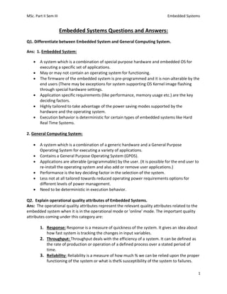
  • 26. MSc. Part II Sem III Embedded Systems 26 8. Upgrades: The upgrade phase of product development deals with the development of up- , grades (new versions) for the product which is already present in the market. Product upgrade results as an output of major bug fixes or feature enhancement requirements from the end user. During the upgrade phase the system is subject to design modification to fix the major bugs reported or to incorporate the new feature addition requirements aroused during the support phase. For embedded products, the upgrades may be for the product resident firmware or for the hardware embedding the firmware. The product resident firmware will· have a version number which starts with version 1.0 and after each firmware modification or bug fix, the firmware version is changed accordingly. Version numbering is essential for backward traceability. Releasing of upgrades is managed through release management. Certain feature enhancements and bug fixes require hardware modification and they are generally termed as hardware upgrades. Firmware also needs to be modified according to the hardware enhancements. The upgraded product appears in the market with the same name as that of the initial product with a different version number or with a different name. 9. Retirement/Disposal: The retirement/disposition phase is the final phase in a product development life cycle where the product is declared as obsolete and discontinued from the market. The disposition of a product is essential due to the following reasons. • Rapid technology advancement. • Increased user needs. The disposal/ retirement of a product is a gradual process: When the product manufacture realizes that there is another powerful technology or component available in the market which is most suitable for the production of the current product, they will announce the current product as obsolete and the newer version/upgrade of the same is going to be released soon. Some products may get a very long 'Life Time' in the market, beginning from the launch phase to the retirement phase and during this time the product will get reasonably good amount of maturity and stability. Q22. Explain Finite State Machine Model for automatic Tea/Coffee vending machine. Ans: In its simplest representation, it contains four states namely; 'Wait for coin' 'Wait for User Input', 'Dispense Tea' and 'Dispense Coffee'. The event 'Insert Coin' (5 rupee coin insertion), transitions the state to 'Wait for User Input’. The system stays in this state until a user input is received from the buttons 'Cancel', 'Tea' or '.Coffee' (Tea and Coffee are the drink select button). If the event triggered in 'Wait State' is 'Cancel' button press, the coin is pushed out and the state transitions to 'Wait for Coin If the event received in the 'Wait State' is either 'Tea' button press, or 'Coffee' button press, the state changes to 'Dispense Tea' and 'Dispense Coffee' respectively. Once the coffee/tea vending is over, the respective states transitions back to the 'Wait for Coin' state. A few modifications like adding a timeout for the 'Wait State' (Currently the 'Wait State' is infinite; it can be re-designed to a timeout based 'Wait State'. If no user input
  • 27. MSc. Part II Sem III Embedded Systems 27 is received within the timeout period, the coin is returned back and the state automatically transitions to 'Wait for Coin' on the timeout event) and capturing another events like, 'Water not available', 'Tea/Coffee Mix not available' and changing the state to an 'Error State' can be added to enhance this design. Event: Insert Coin Action: OK Event: Cancel Button Action: Coin Out State A State B State C State D Event: Coffee Dispensed Action: Done Action: Done Event: Tea Dispensed Event: Tea Button Press Action: Dispense Tea Event: Coffee Button Press Action: Dispense Coffee
  • 28. MSc. Part II Sem III Embedded Systems 28 Q23. Explain Re-entrant function. Ans: • Functions which can be shared safely with several processes concurrently are called re-entrant functions. When a re-entrant function is executing, another process can interrupt the execution and can execute the same re-entrant function. The "another process" referred here can be a thread in a multithreaded application or can be an Interrupt Service Routine (ISR). • Re-entrant function is also referred as 'pure' function. Embedded applications extensively make use of re-entrant functions. Interrupt Service Routine (ISR) in Super loop based firmware systems and threads in RTOS based systems can change the program's control flow to alter the current context at any time. • When an interrupt is asserted, the current operation is put on hold and the control is transferred to another function or task (ISR). • In embedded applications, a function/subroutine is considered re-entrant if and only if it satisfies the following criteria. 1. The function should not hold static data over successive calls, or return a pointer to static data. 2. All shared variables within the function are used in an atomic way. 3. The function does not call any other non-reentrant functions within it. 4. The function does not make use of any hardware in a non-atomic way. Rule# 1: deals with variable usage and function return value for a reentrant function. Rule# 2: deals with 'atomic' operations. Rule #3: If a re-entrant function calls another function which is non-reentrant, it may create potential damages due to the unexpected modification of shared variables if any. Rule# 4: deals with the atomic way of accessing hardware devices. The term 'atomic' in hardware access refers to the number of steps involved in accessing a specific register of a hardware device.