

Recommended
More Related Content
Viewers also liked
Viewers also liked (20)
Similar to Signal flow graph
Similar to Signal flow graph (20)
Recently uploaded
Recently uploaded (20)
Signal flow graph
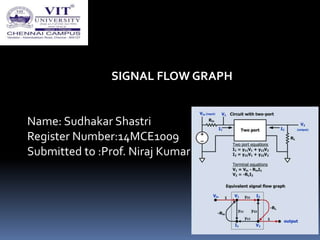
- 1. SIGNAL FLOW GRAPH Name: Sudhakar Shastri Register Number:14MCE1009 Submitted to :Prof. Niraj Kumar
- 2. Contents Introduction Basic components Representation of source and load Rules of SFG Construction of SFG Applications
- 3. Introduction SFG is a useful technique for analysis of microwave networks in terms of reflected and transmitted waves. Signal and Scattering parameters can be described using a graphical technique called Signal Flow Graphs (SFG).
- 4. BASIC COMPONETNS Nodes Branches
- 5. REPRESENTATION OF SOURCE AND LOAD Source representation Load representation
- 6. RULES OF SFG Series rule Parallel rule Recursive rule (self loop) Node splitting rule
- 7. RULE 1:Series Rule S-parameters for paths in series can be combined into one path by multiplying the s- parameters. V3=S32S21V1
- 8. RULE 2:Parallel Rule S-parameters for multiple paths connecting the same two nodes can be combined into a single path by adding the s-parameters. V2=SaV1 + SbV2=V1(Sa + Sb)
- 9. RULE 3:Recursion Rule When a node has a self loop of co-efficient S, the self loop Can be eliminated by multiplying coefficients of the branches feeding that node by 1/(1-S) V2=S21V1 + S22V2 V3=S32V2 Eliminating V2 V3=S32S21V1/1-S22
- 10. RULE 4:Node Splitting Rule A node may be a split into two separate nodes as long as the resulting flow graph contains, once and only once, each combination of separate input and output branches that connect to the original node V4=S42V2 =S21S42V1
- 11. APPLICATIONS Use signal flow graph to derive expressions for Γin and Γout For the two port network given below:
- 12. CONTD…
- 13. CONTD…