4. StartIng of InductIon motor
For induction motors, the starting torque (LRT) is approximately
proportional to the square of the starting current (LRA) drawn from the
line. LRT I∝ 2
This starting current is proportional to the applied voltage (V)
Torque can also be considered to be approximately proportional to the
applied voltage. LRT V∝ 2
An induction motor will develop far too much torque when connected
directly to the supply.
At the instant of start-up, there are some un-necessary effect on
electrical and the mechanical components.
4
5. un-neceSSarY mechanIcal effectS
5
The sudden impact at start up on the load, followed by the
rapid acceleration to full speed causes excessive wear on :-
Belts and pulleys
Gears and chains
Couplings and bearings
Cavitation in pumps etc.
6. un-neceSSarY electrIcal effectS
6
A heavy current surge on the electrical supply which can
be severe enough to cause voltage dips and flickering
lights.
Burning of contacts due to high currents which are many
times the motor full-load current.
7. ProblemS arISeS bY theSe effectS
Continuous maintenance.
Greater chance of unscheduled shutdowns
Oversized mechanical and electrical components to
cater for the power surge on start up.
Short component life.
7
8. SolutIon of the ProblemS…..
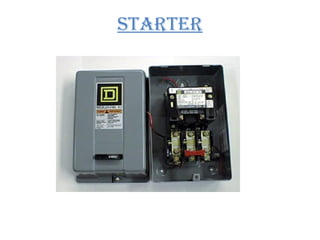
Starter
By Adjusting voltage during starting, the current drawn by the motor and the
torque produced by the motor can be reduced and controlled.
8
10. functIon of Starter
Start and stop the motor.
Limit inrush current where necessary.
Permit automatic control when required
Protect motor and other connected equipments from over
voltage, no voltage, under voltage, single phasing etc.
11. motor Starter featureS.
Rated by current (amperes) or power (horsepower)
Remote ON/OFF control
Motor overload protection
Starting and stopping (electrical life)
Plugging and jogging (rapid making and breaking current)
12. tYPeS of Starter for 3-Ph
InductIon motorS
For slip-ring induction motors:
Rotor rheostat starter
For squirrel cage induction motors:
D.O.L starter
Primary resistance starter
Auto transformer starter
Star delta starter
Other starters:
Soft starters
13. StartIng of SlIP rIng InductIon
motor
In case of slip ring induction motors it is possible to add
external resistance in rotor phases as wound rotor has 3-
-phase star connected winding to limit the starting high
current.
15. In rotor resistance starter the three terminals of the rotor
winding are connected to a variable external resistances
through slip rings.
Full supply voltage is applied across the stator. Resistances are
fully in the circuit at starting , so that the starting current is
reduced. The external variable resistance connected in each
phase of the rotor circuit not only reduce the current at starting
but increases the starting torque also due to improvement in
power factor.
The rotor circuit resistance is gradually cut out , as the motor
speeds up and during normal running condition ,the rotor
circuit resistance is completely cut out and the slip rings are
short circuited.
17. D.O.L.(Direct On Line) starter
A Starter Which Connects A Motor Directly Across The
Line Is Called D.O.L. Starter.
In This Method, The Motor Is Connected By Means Of A
Starter Across The Full Supply Voltage.
It Is Very Simple, Inexpensive, Easy To Install And Maintain.
It Consist - START Button
- OFF Button
- Electromagnetic Contector
- Overload Relay
Switching By This Starter Is Directly From Line Without Any
Provision To Control The Starting Current i.e. There Is No
Device To Reduce The Starting Current In This Starter.
18. WirinG DiaGraM
OF D.O.L starter
L1,L2,L3 - LINES
M – MAIN CONTACTS
M(a) – AUXILIARY OR
MAINTAINING CONTACT
S1 – START PUSH BUTTON
S2 – OFF PUSH BUTTON
OLC – OVERLOAD RELAY
COIL
OL – OVERLOAD RELAY
CONTECT
C – MAGNETIC COIL OR
OPERATING COIL
19. OperatiOn OF D.O.L starter
1) When START Button Is Pressed
When Start(s1) Button is pressed, Path is
L1 - S2 - S1 – C – OL - L2
Coil C Is Energized ,It Closes Contacts M And Connects The
Motor Across The Line.
Maintaining Contact M(a) Is Used To Keep The Holding Or
Operating Coil Energized After The Finger Is Removed From
START Push Button (S1).
20. 2) When OFF Button Is Pressed
When OFF(s2) Button is pressed, Path is
Disconnected.
Coil C Is De-Energized, The Main Contacts M Are
Opened. Supply To Motor Is Disconnected And
Motor Stops.
21. Basically There Are Two Types Of Protection In This Type
of Starter
1)Under Voltage Protection
2)Overload Protection
1) Under Voltage Protection
When Supply Voltage Is Not Sufficient Or There Is
Failure Of Power Supply , The Coil C Is De-Energized
And Motor Will Be Disconnected.
22. 2) Overload Protection
The Motor Is Protected Against Overload By A
Thermal Overload Relay Which Open Circuits the
Control Circuit When Overload occure.
The Normally Closed Contacts O.L Is Opened And The
Contactor Coil C is De-Energized To Disconnect The
Motor
From The Supply.
Rate Of Temperature Is Very High So Motor May Be
Damaged If The Starting Period Is large. Which May Be
Due To Excessive Load Or Excessive Voltage Drop In The
Supply Lines.
Only Used For Less Than 5 KW Squirrel Cage Induction
.
23. cOMpOnents OF D.O.L. starter :Components of a DOL Starter
Overload Unit (Thermal type)
Main pole terminals 1, 3 & 5
When motor overheats due to overload
conditions, main poles latch open
Auxiliary contacts also latch open and
when interlocked within control
circuit prevents motor restarting by
itself when cool.
Main pole terminals 2, 4 & 6
N/O
Auxiliary
contacts
97 & 98
N/C
Auxiliary
contacts
95 & 96
Reset
button
Red pushbutton can be used to reset
24. cOMpOnents OF a DOL starter:
Start and Stop pushbuttons
Start button is green and
flush mounted
Stop button is red and
protruding
N/O contact N/C contact
Emergency Stop button has a
red mushroom head which
latches in and must be turned
to release
Contacts at the
back of
switches can
be either N/O
or N/C
27. In this method of starting of 3-Phase induction motor ,
primary resistance are connected in all the three phase of the
stator winding, as a result the applied voltage across the
stator winding at the instant of starting in reduced to a
fraction x of the rated voltage of the motor. Therefore the
initial high starting current will also reduce by the same
fraction.
If x = fraction of voltage (V) reduced by the stator resistors
28. The torque developed by the motor is directly proportional to
the square of applied voltage, so if the voltage applied across
the motor terminal is reduced by fraction X ,starting current is
reduced by fraction X ,but the starting torque is reduced by a
fraction x² of the obtainable with direct switching.
The purpose of primary or starting resistors is to drop some
voltage and hence reduce the voltage applied across the motor
terminals.
29. Advantages:
High power factor during start.
Smooth acceleration.
Less expensive than auto-transformer starter in lower output ratings.
Closed transition starting.
Disadvantages:
Heat is given of T by the resistors.
Expensive resistors are required because starting duration usually exceeds 5
seconds.
Low torque efficiency.
Note: This method is suitable for starting of small machines only
32. This is very commonly used starter, compared to the other
types of the starters.
Star-delta starter can be used, provided the stator of the 3-Ø
induction motor is designed for delta connection during its
normal operation.
At starting, the stator winding is connected in star, therefore
the applied voltage to each phase of winding is 1/√3 of the
rated voltage of the motor.
When the motor has picked-up the speed(say 70 to 80% of its
normal speed ) the phases of the stator winding are connected
in delta.
Now full supply voltage is applied across the stator windings.
33. This method is cheap but limited to applications where high
starting torque is not necessary e.g., machine tools, pumps,
motor-generator sets etc.
The method is unsuitable for motors for voltage exceeding
3000 V because of the excessive number of stator turns needed
for delta connection.
Such starters are employed for starting 3-phase squirrel cage
induction motors of rating between 4 and 20 k W.
34. advantageS of Star-delta
Starter:
The operation of the star-delta method is simple and rugged
It is relatively cheap compared to other reduced voltage
methods.
Good Torque/Current Performance.
It draws 2 times starting current of the full load ampere of the
motor connected
35. diSadvantageS of Star-delta
Starter:
Low Starting Torque, only 33% starting torque
Break In Supply – Possible Transients
Six Terminal Motor Required (Delta Connected).
It requires 2 set of cables from starter to motor.
38. CirCuit and funCtion
An auto-transformer starter makes it possible to start squirrel-
cage induction motors with reduced starting current, as the
voltage across the motor is reduced during starting.
In contrast to the star-delta connection, only three motor leads
and terminals are required. On starting, the motor is
connected to the tapping of the auto-transformer.
39. Soft motor Starting BaSiCS
If you reduce voltage by 50%, the result is a 75% reduction in
motor torque.(.5)(.5)22
= .25 or 25% of Locked Rotor Torque= .25 or 25% of Locked Rotor Torque
180%180%
100%100%
100%100%00 Percentage of Full Speed
Full Voltage Torque
Physics of Reduced Voltage and Motor Torque
Reduced Voltage Torque
Percentage
of Full Rated
Torque
40. Soft motor Starting BaSiCS
40
Example
100%0 Speed -RPM
Torque
(ftlb)
100%
72%
25%
600%
510%
300%
100% Voltage
85% Voltage
50% Voltage
Full Load
Torque required
by the load
%FLA
(amps)
Current
Torque
41. Soft motor Starting BaSiCS
41
Example
100%0 Speed -RPM
Torque
(ftlb)
100%
72%
25%
600%
510%
300%
100% Voltage
85% Voltage
50% Voltage
Full Load
Torque required
by the load
%FLA
(amps)
Current
Torque
42. Starting CharaCteriStiCS:
Motor terminal voltage less than line voltage (by transformer
ratio).
Motor current exceeds line current (by inverse of transformer
ratio).
Starting torque is reduced by the square of the terminal
voltage.
43. AdvAntAges:
Voltage is reduced by transformation and not by dropping the
voltage in resistors, and therefore, the current and power drawn
from the supply mains are also reduced in comparison to resistor
starting.
Adjustment of starting voltage by selection of proper tap on the
auto-transformer.
The method is suitable for long starting periods.
Motor current larger than supply current.
This method can be used for starting of star-connected as well as
delta-connected motors.
44. dIsAdvAntAges:
Low power factor.
Higher cost in case of lower output rating motors.
This method is often employed for starting of large cage
motors (rating exceeding 20 kW).
45. dIfference between dOL/stAr deLtA
/AutOtrAnsfOrmer
Sr. DOL Starter Star delta starter Auto transformer
starter
1 Used up to 5 HP Used 5 HP to 20HP Used above 20 HP
2 Does not decrease
the starting current
Decreases the starting current
by 1/3 times
Decreases the starting
current as required
3 It is cheap It is costly It is more costly
4 It connects directly
the motor with
supply for starting
as well as for
running
It connects the motor first in
star at the time of starting in
delta for running
It connects the motor
according to the taping
taken out from the auto
transformer
47. sOft stArter
Soft-Starter is an electronic starter
designed to accelerate, deaccelerate
three-phase induction motors and to
control the voltage applied on the motor
during start and stop.
47
49. 49
By using six SCR’s in a back to back configuration , the soft starter is able to regulate the
voltage applied to the motor during starting from 0 volts up to line voltage.
Feedback from the motor to the logic circuit used to control the SCR firing for stabilization of
motor acceleration
Frequency do not change as in VFD
Only the voltage and current changes.
Fig.1
stArtIng PrIncIPLe Of sOft stArter
50.
51. feAtures Of sOft stArter
Soft start and soft stop
Pulse (kick) start
Current Control ramps
Pump Control characteristics
Tacho/Encoder feedback
Dual Adjust - start/stop characteristics for varying
loads
51
52.
53. dIfference between sOft stArter
And AutOtrAnsfOrmer
Sr. No. Soft Starter Autotransformer
1 No electrical moving
contacts and no oil hence
no sparking and hazards.
Circuitry consists of several
moving parts and hence
sparking is unavoidable.
2 No limitations on the No. of
starts and No. of stops per
hour.
Limited No of starts and
stops per hour because of:
motor windings getting
heated.
3 In rush (starting) current
restricted to 200% of rated
full load current (FLC).
Inrush current restricted to
maximum of 400% of the
FLC.
4 Current limit facility is
available which limits the
current drawn by the
motor plus the load to a
desired safe value.
This facility is not available
54. Act fAst And InItIAte fIrst
• बड़ा सोचो
• तेजी से सोचो व
• सबसे पहले सोचो
• िवचारो पर िकसी का
• एकािधकार नही होता.
----धीरभाई अमबानी