Download as PDF, PPTX
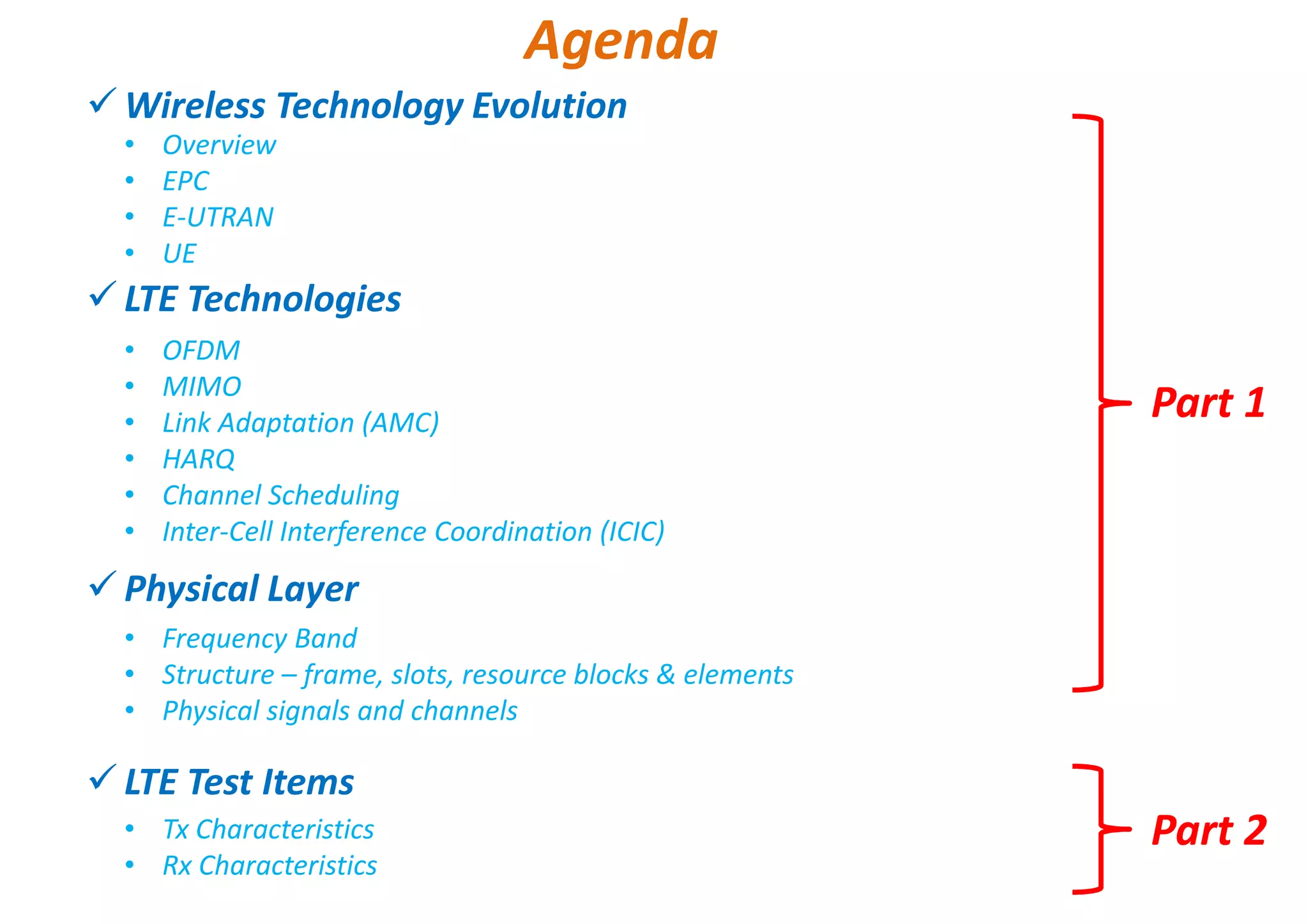


- The document discusses LTE introduction and technologies. It provides an overview of the evolution of wireless technologies towards LTE. - Key aspects of LTE covered include the Evolved Packet Core (EPC), the radio access network E-UTRAN consisting of eNodeBs, and LTE user equipment (UE). - Physical layer technologies enabling LTE such as OFDM, MIMO, link adaptation, and channel scheduling are discussed. The document also outlines the LTE network architecture and components.
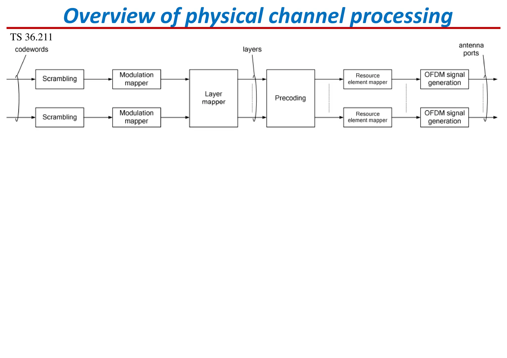
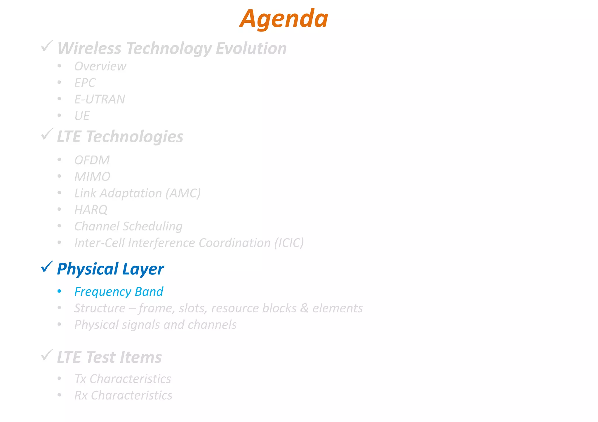
Introduction to LTE technology and an overview of its physical layer components.
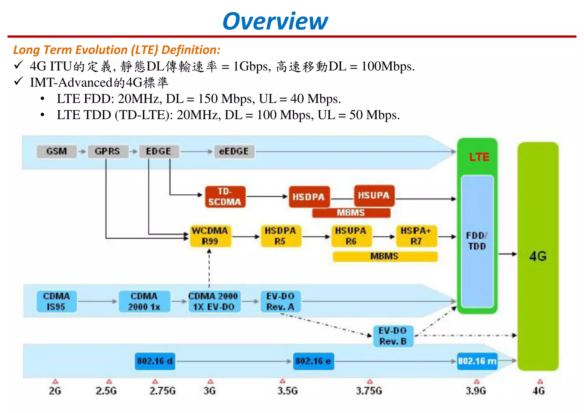
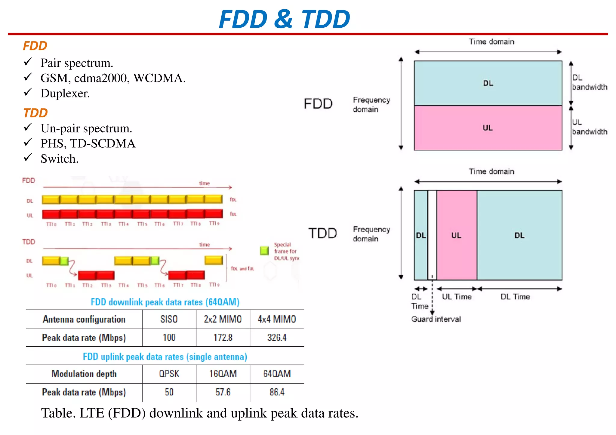
Definition of LTE as part of 4G, with key data rates for FDD and TDD standards.
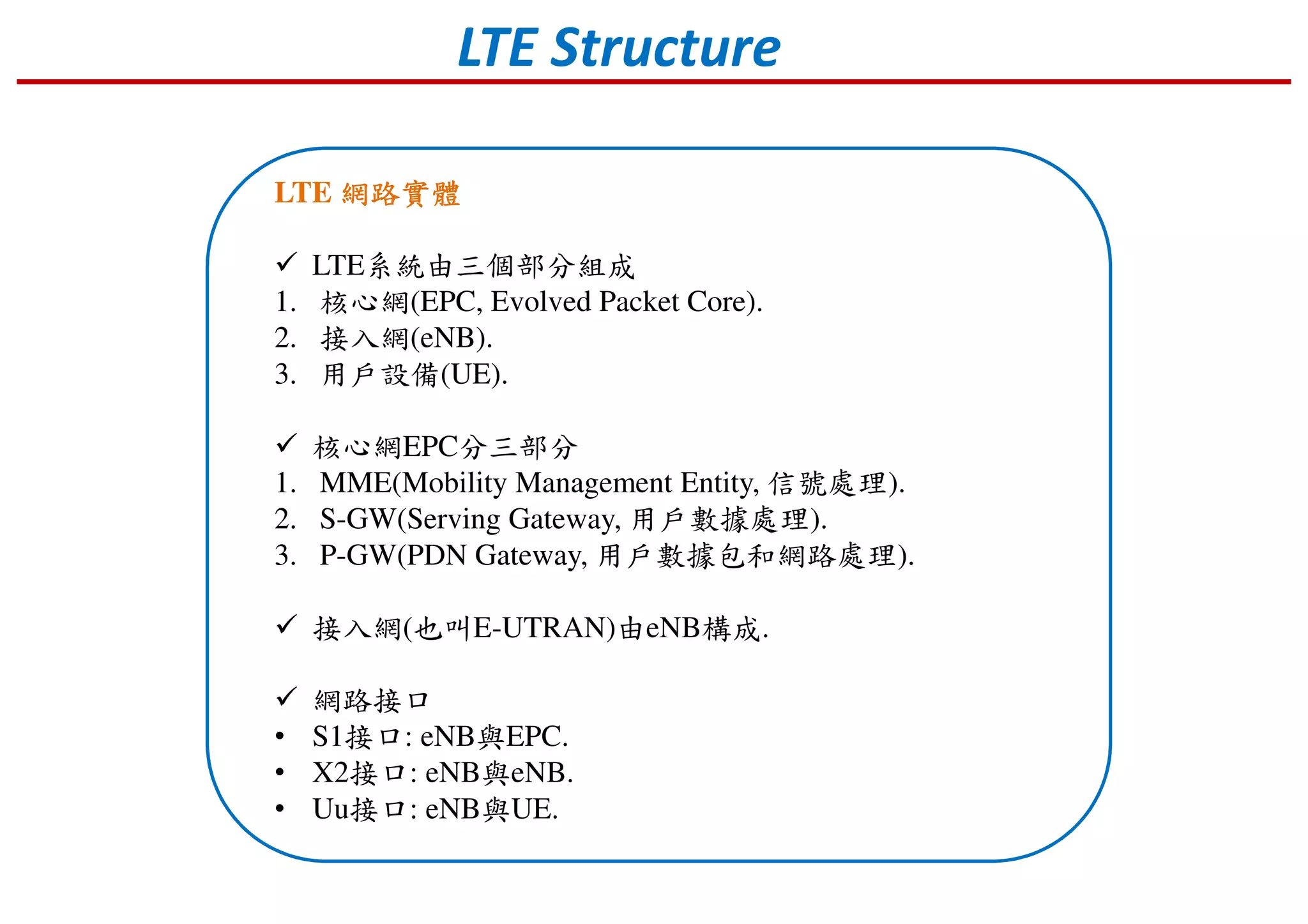
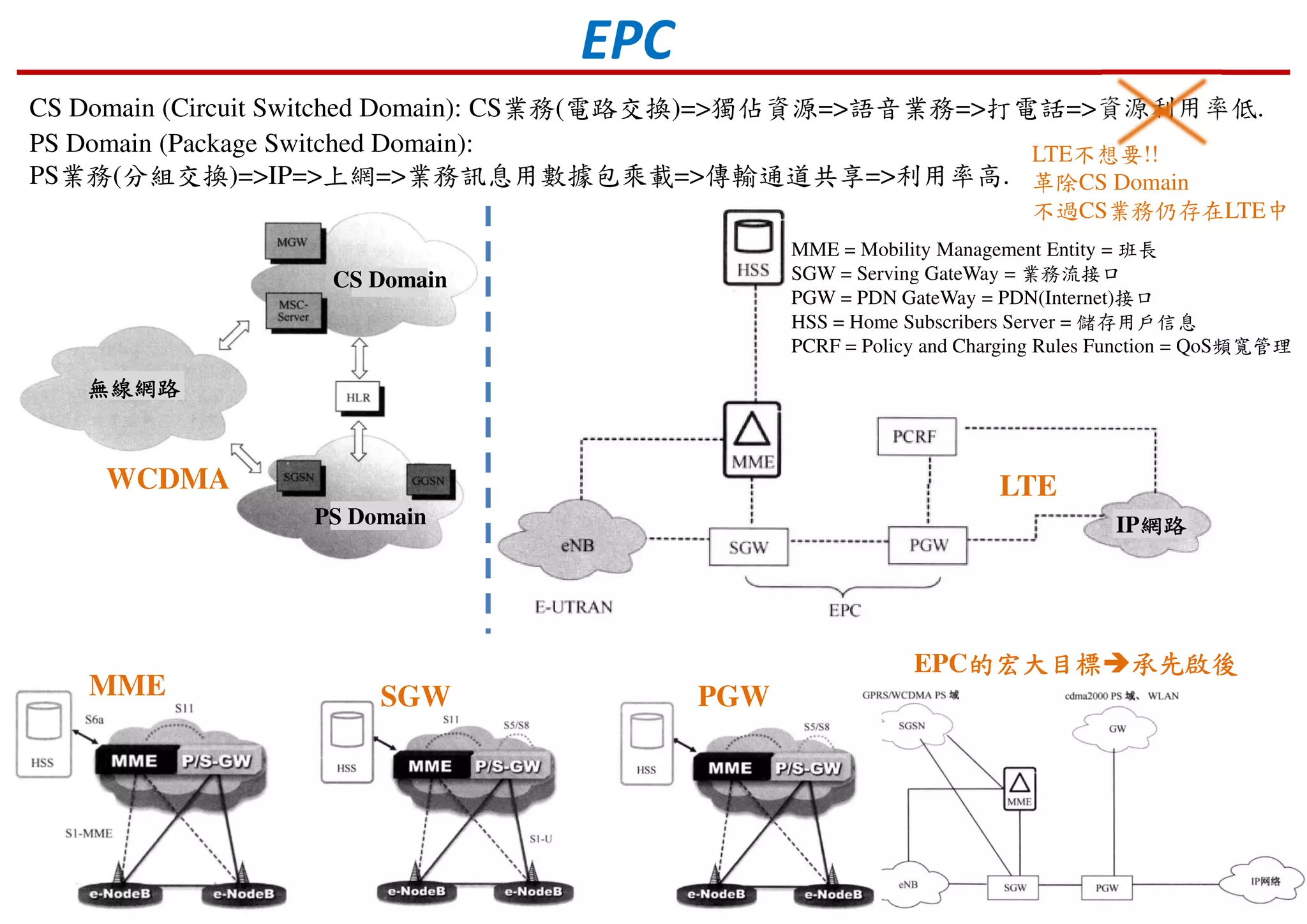
Introduction to network architecture of LTE, including core network components and interfaces.
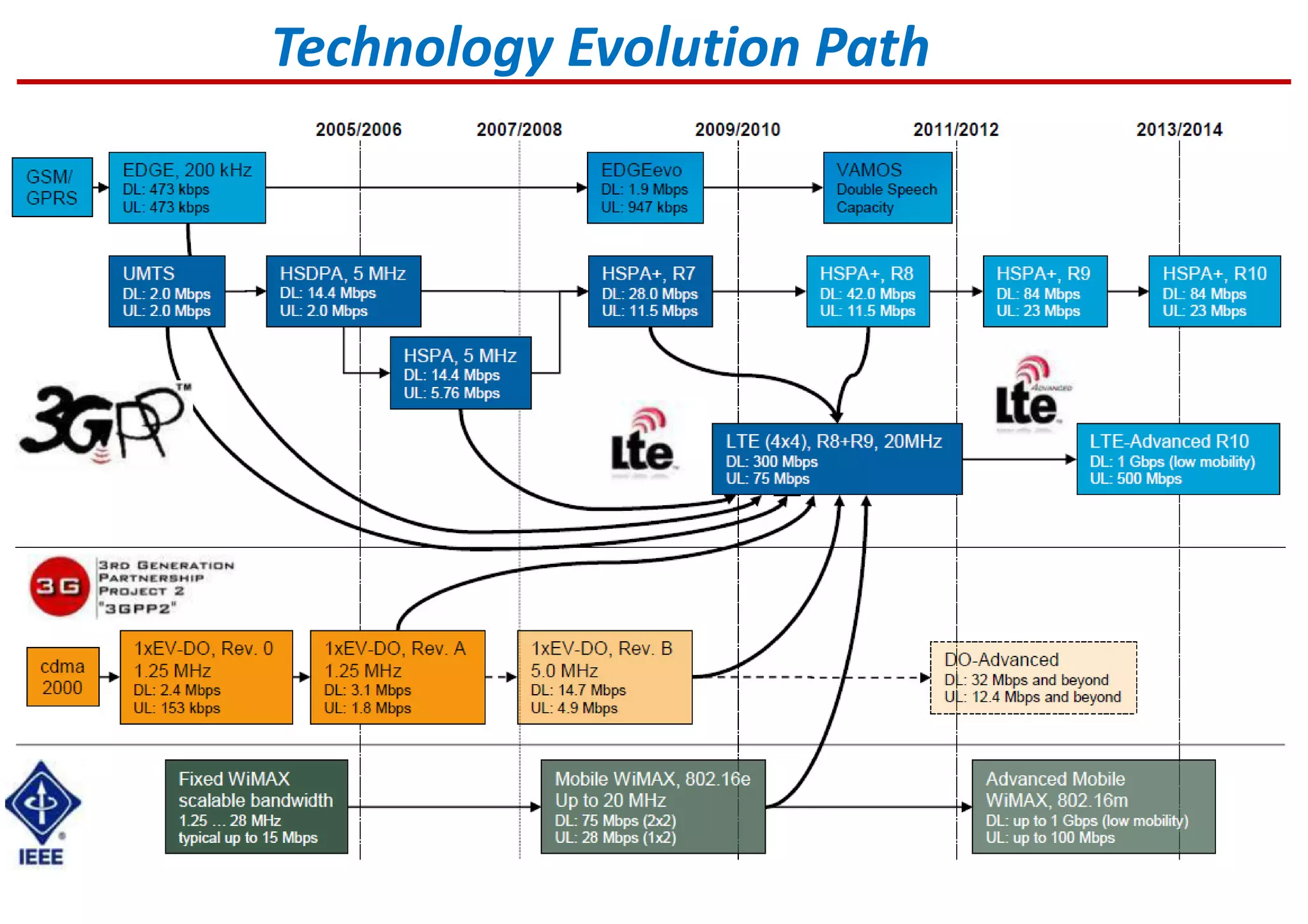
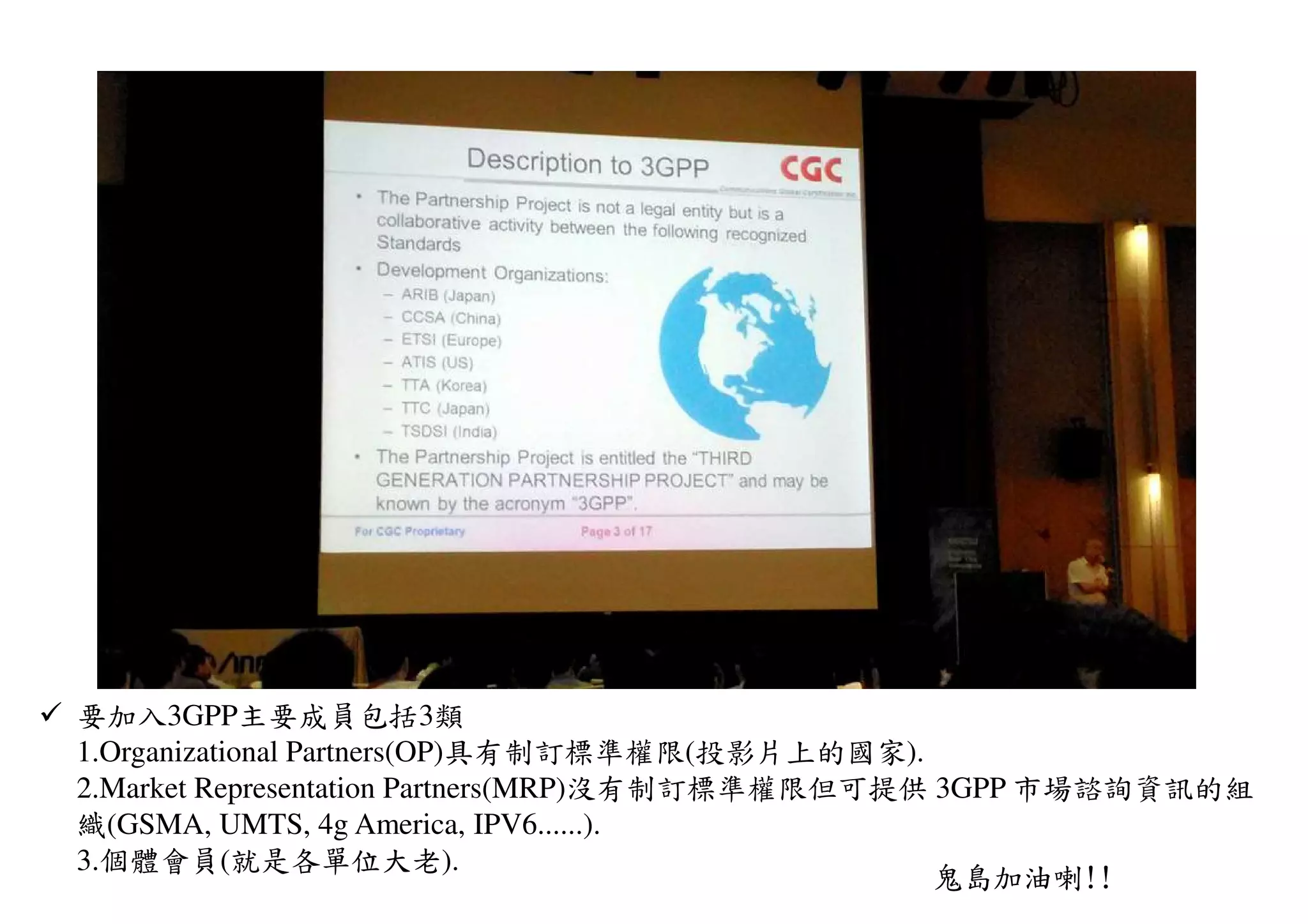
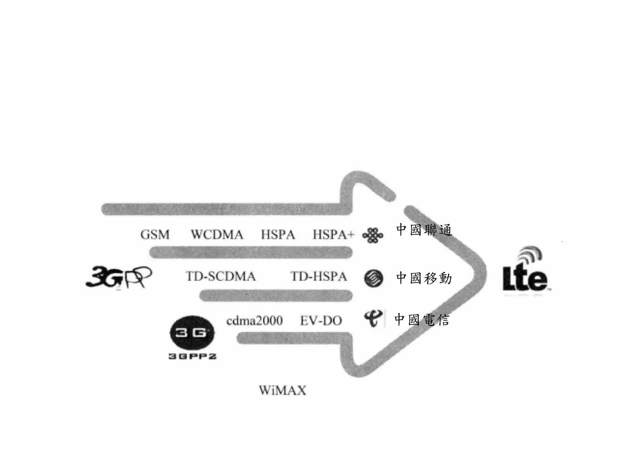
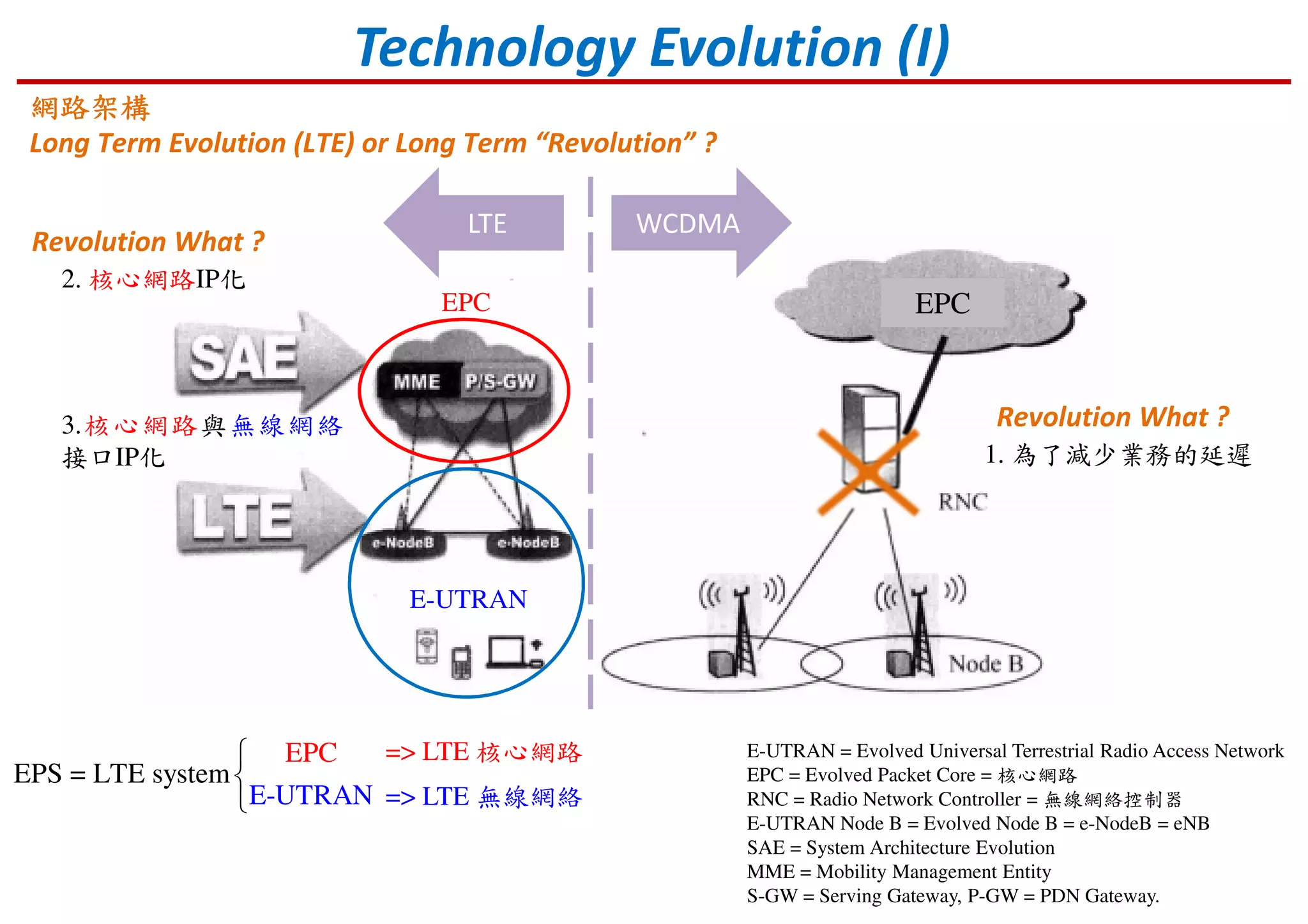
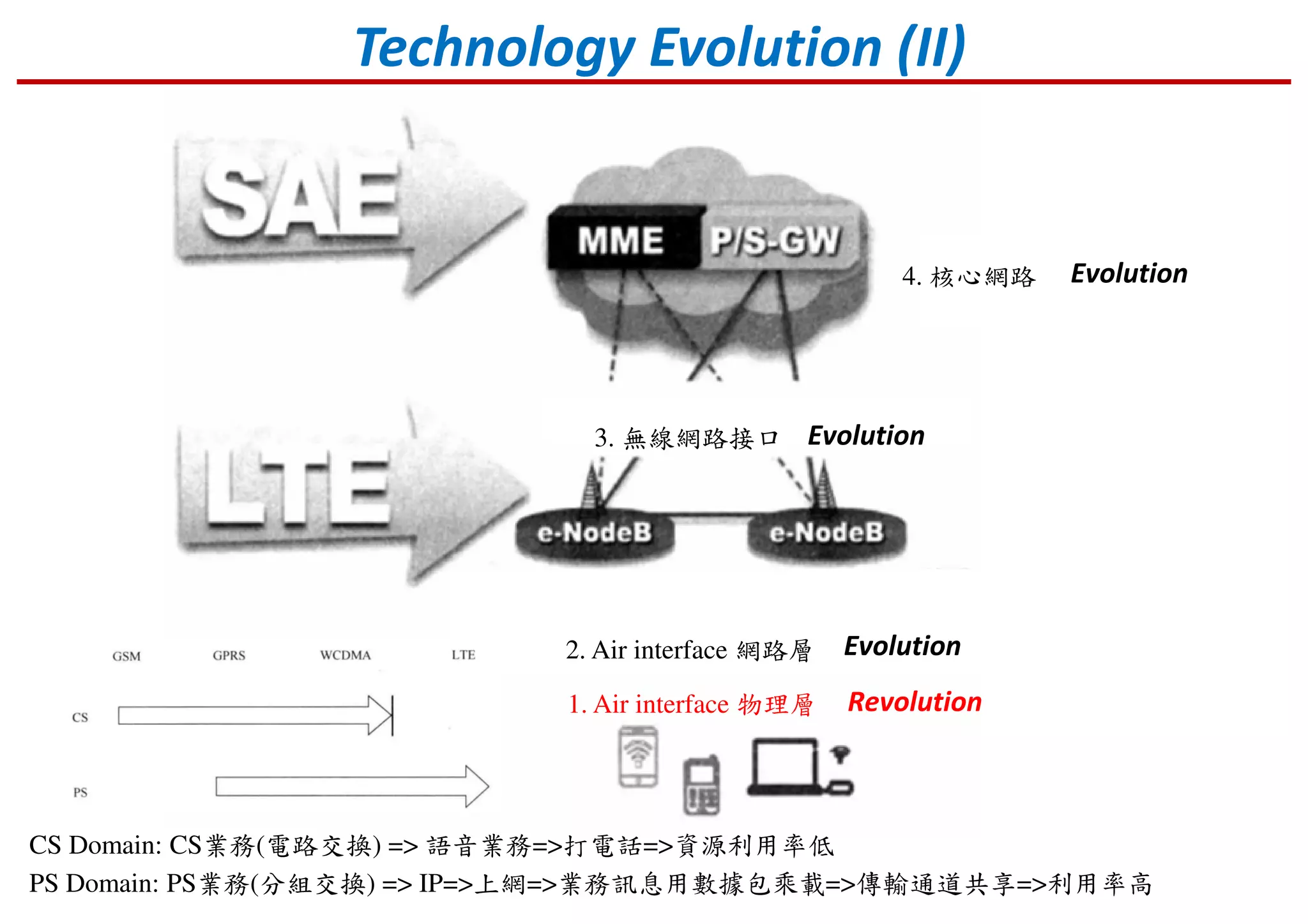
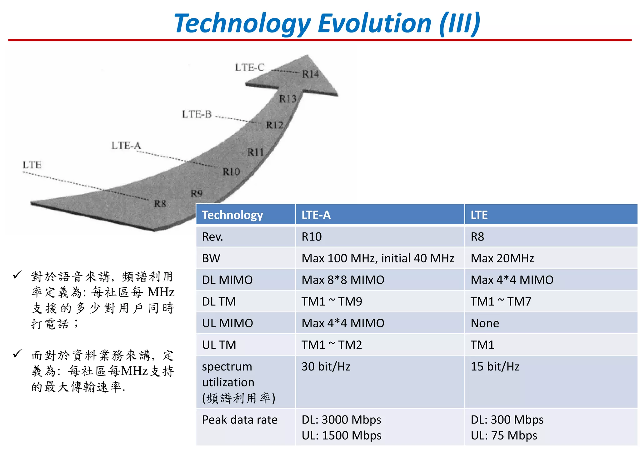
Discussion on the evolution of technology leading to LTE and its architecture.
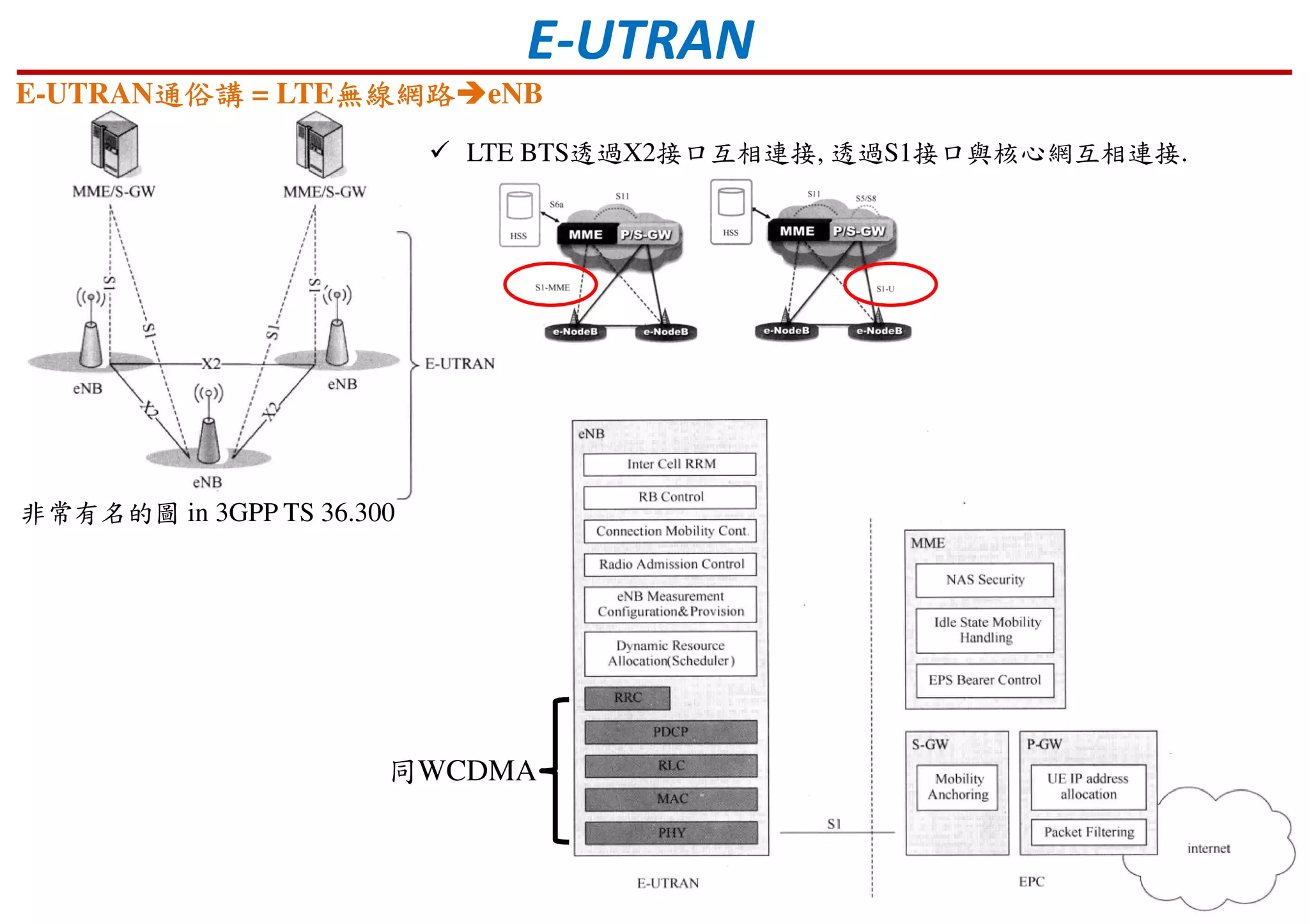
Details of network components E-UTRAN and interface connections and functionalities.
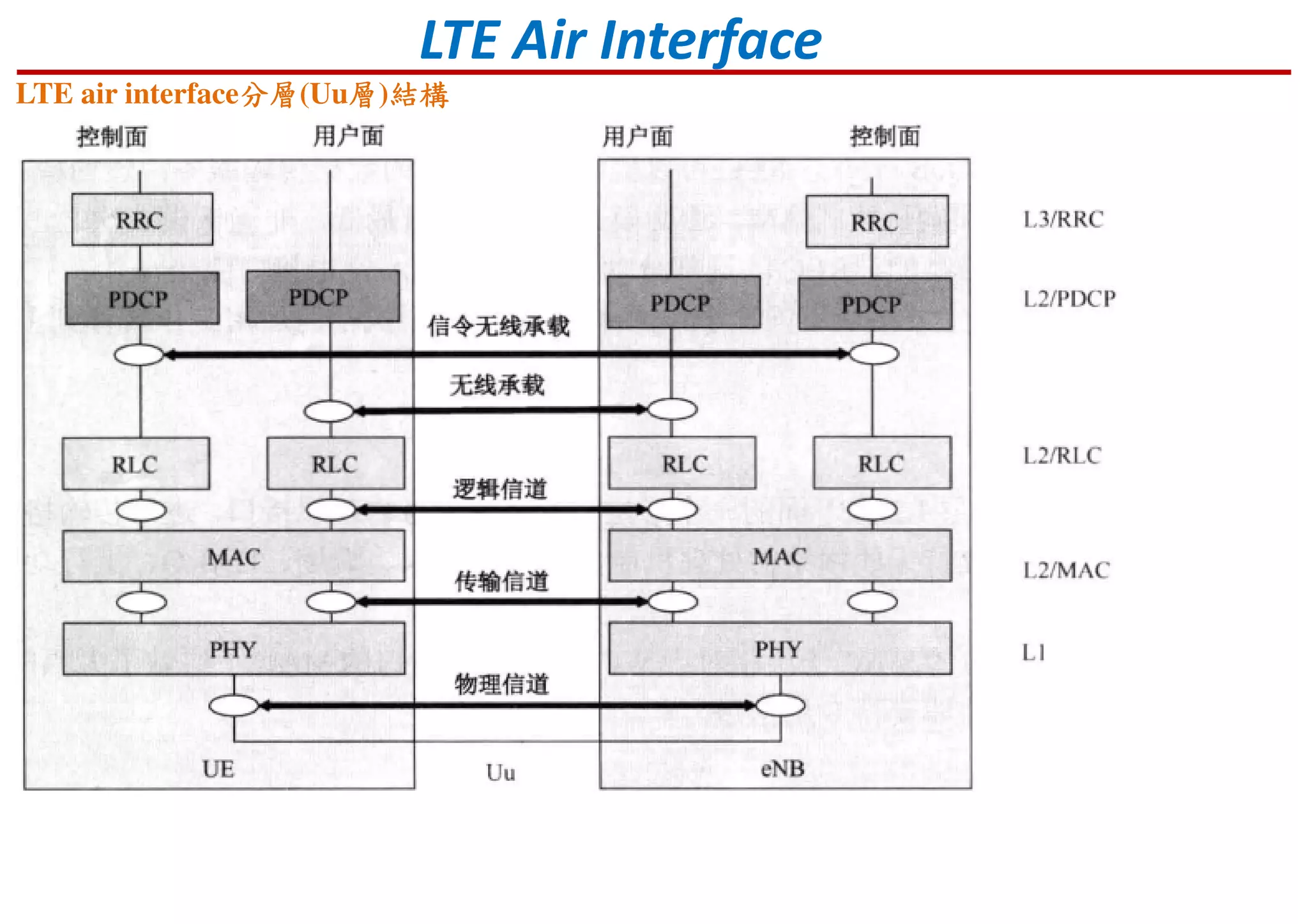
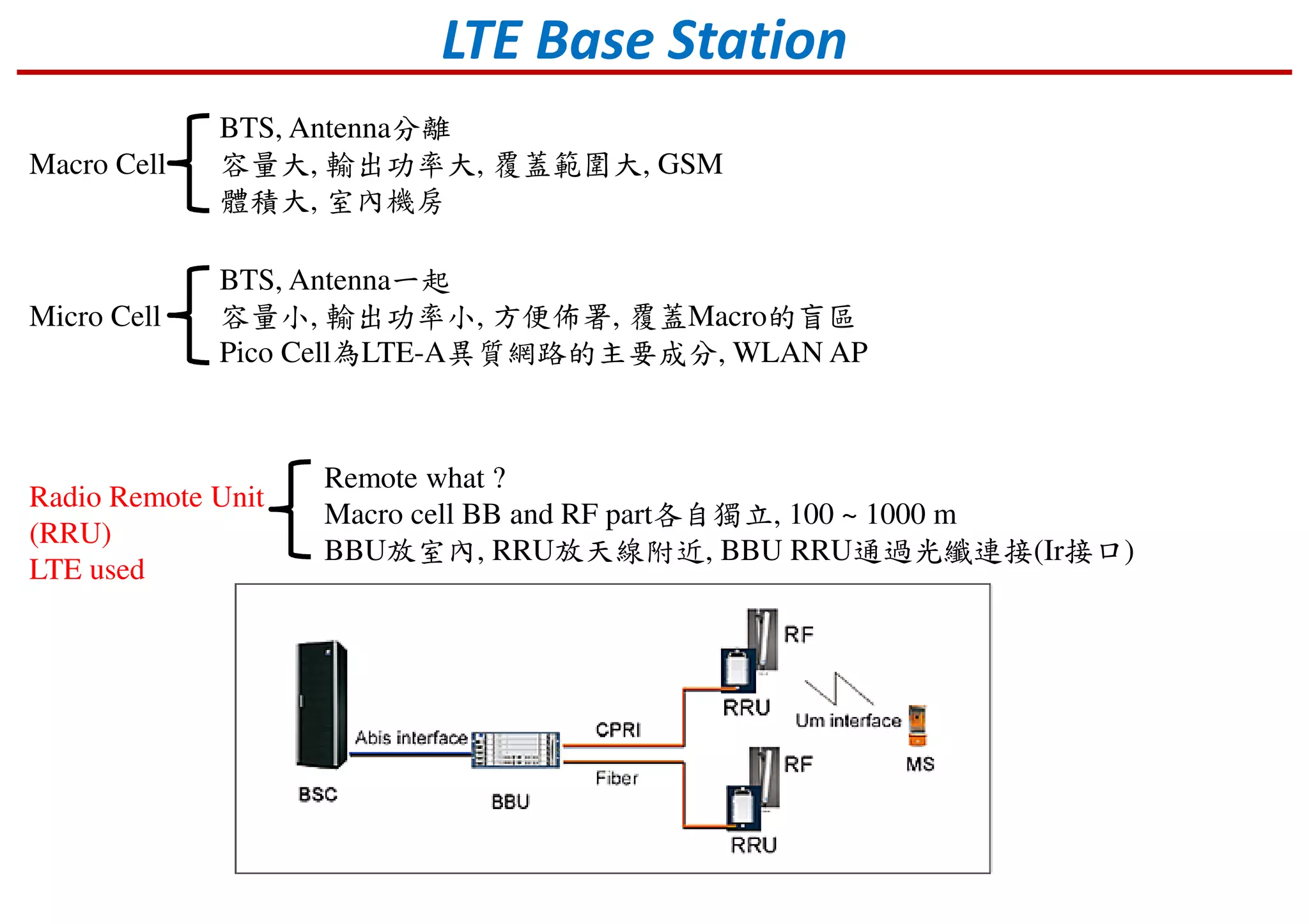
Description of LTE air interface structure and various cell types: macro, micro, and pico.
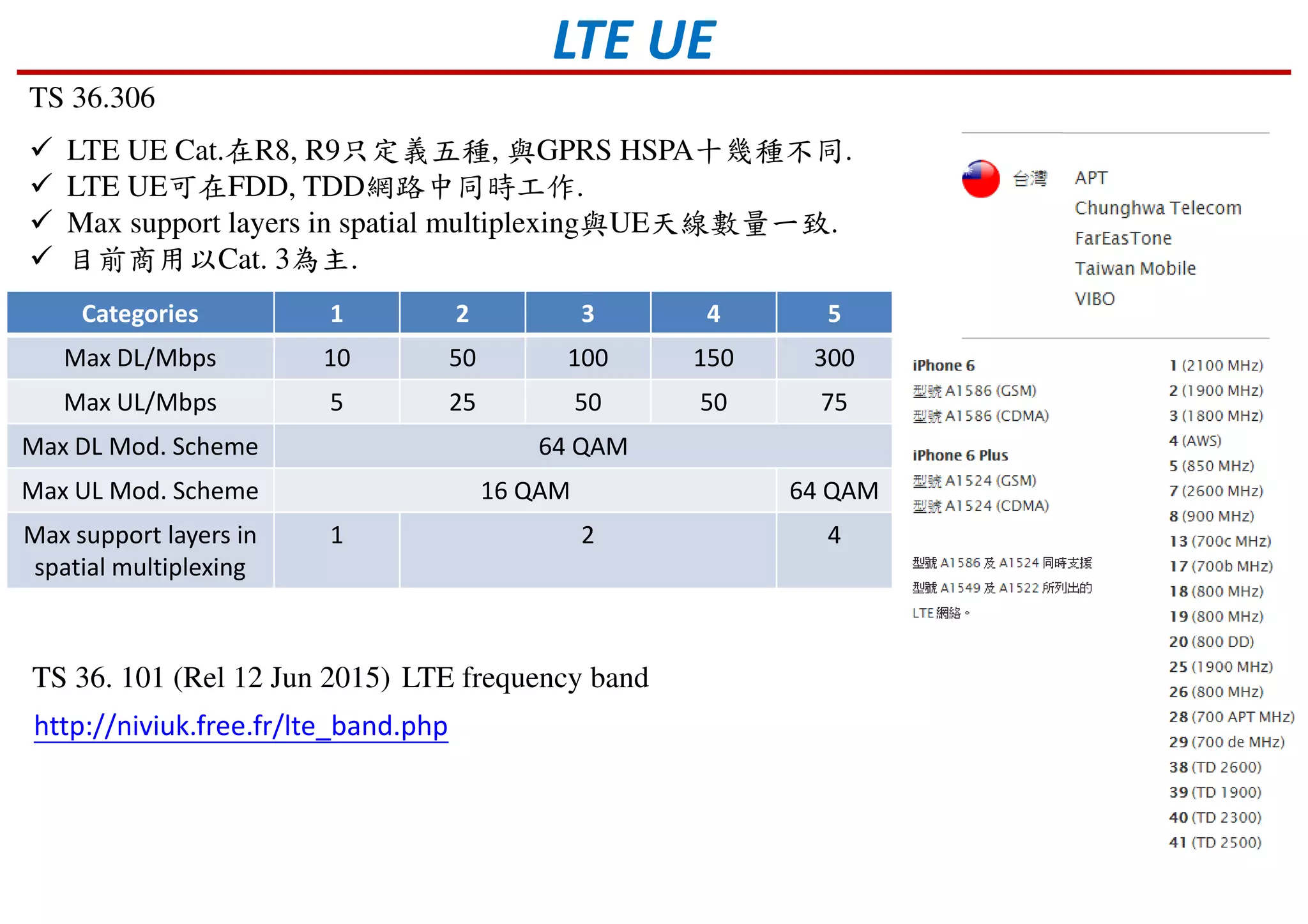
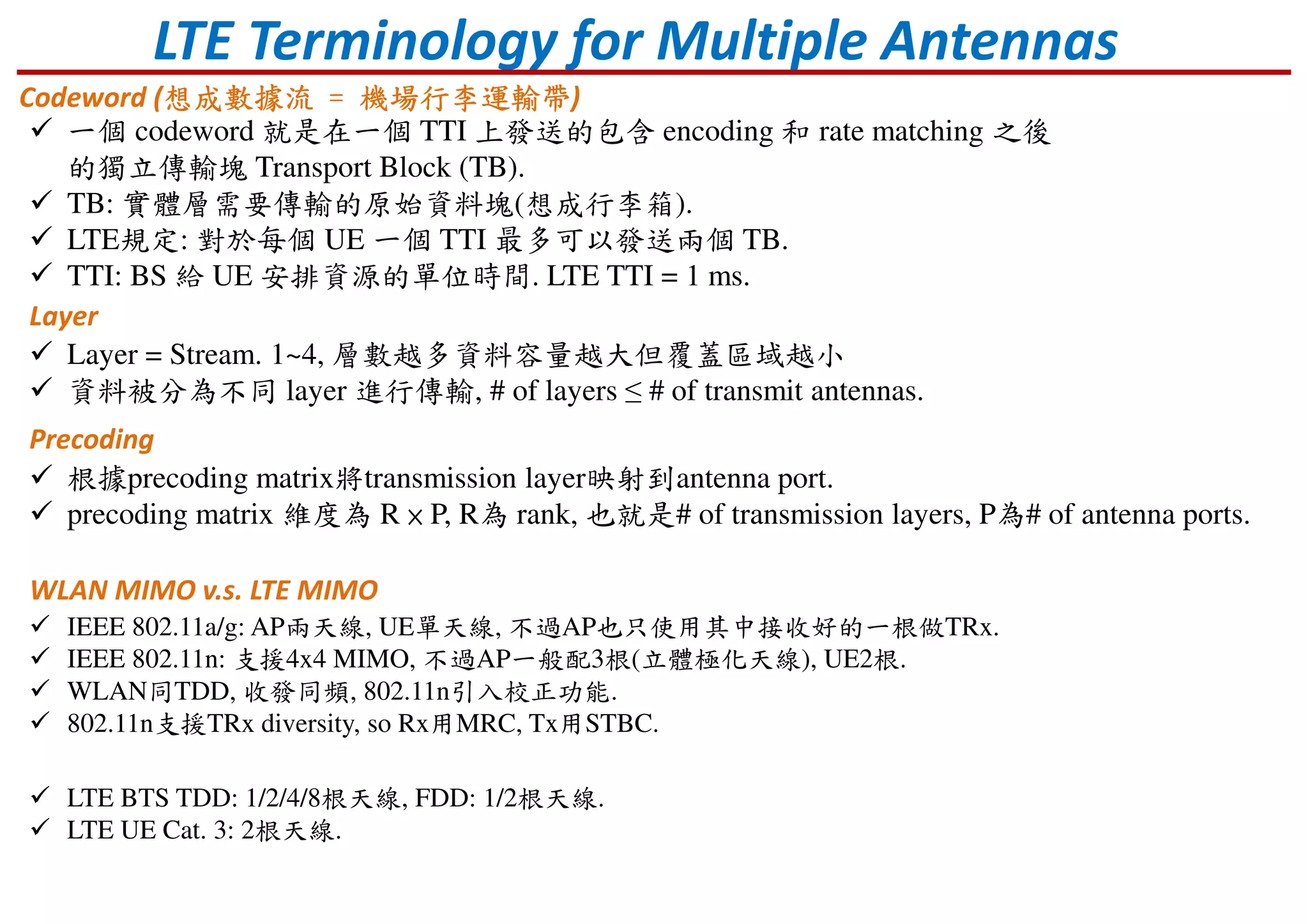
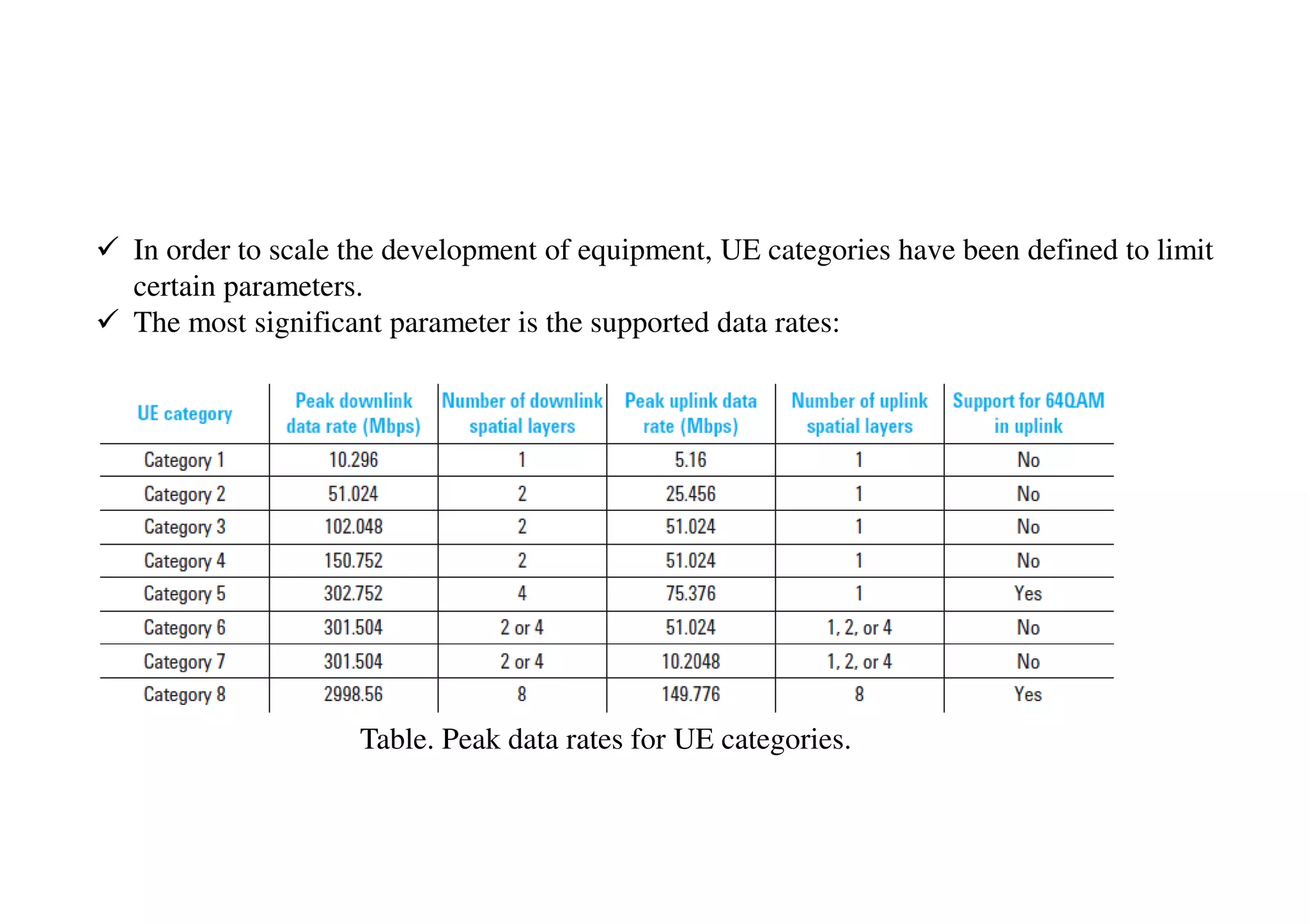
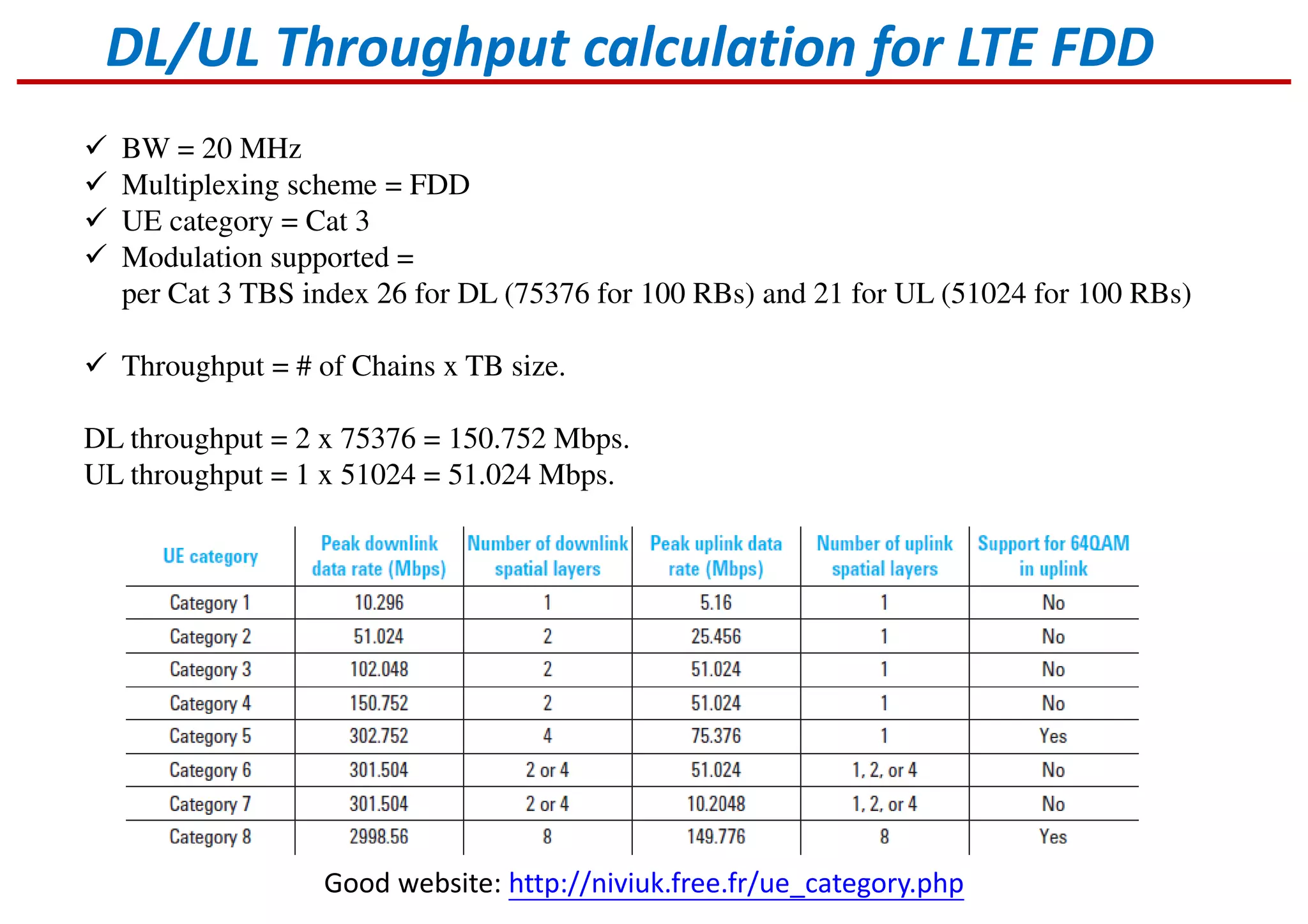
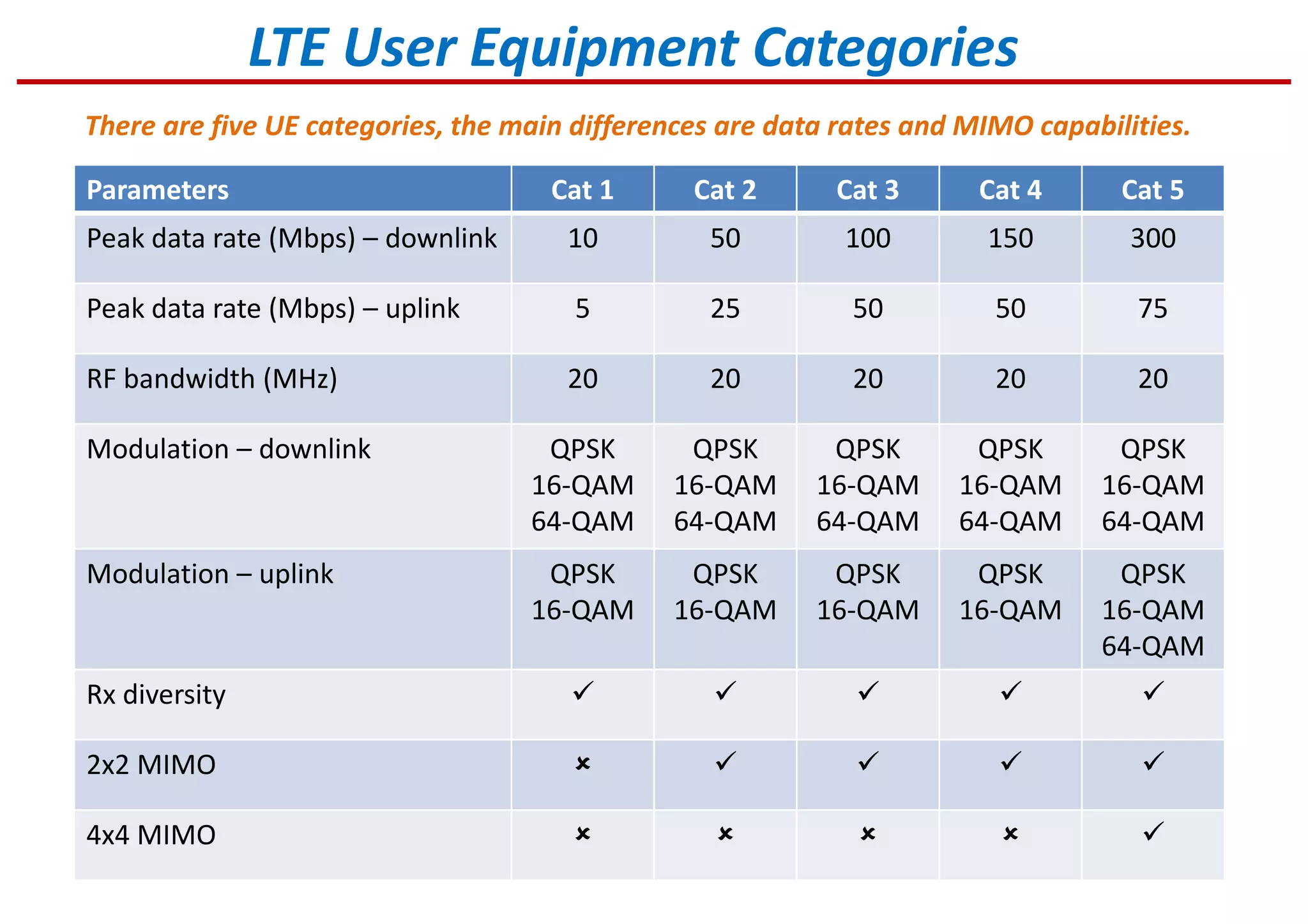
LTE User Equipment categories with data rates, specifications, and MIMO capabilities.
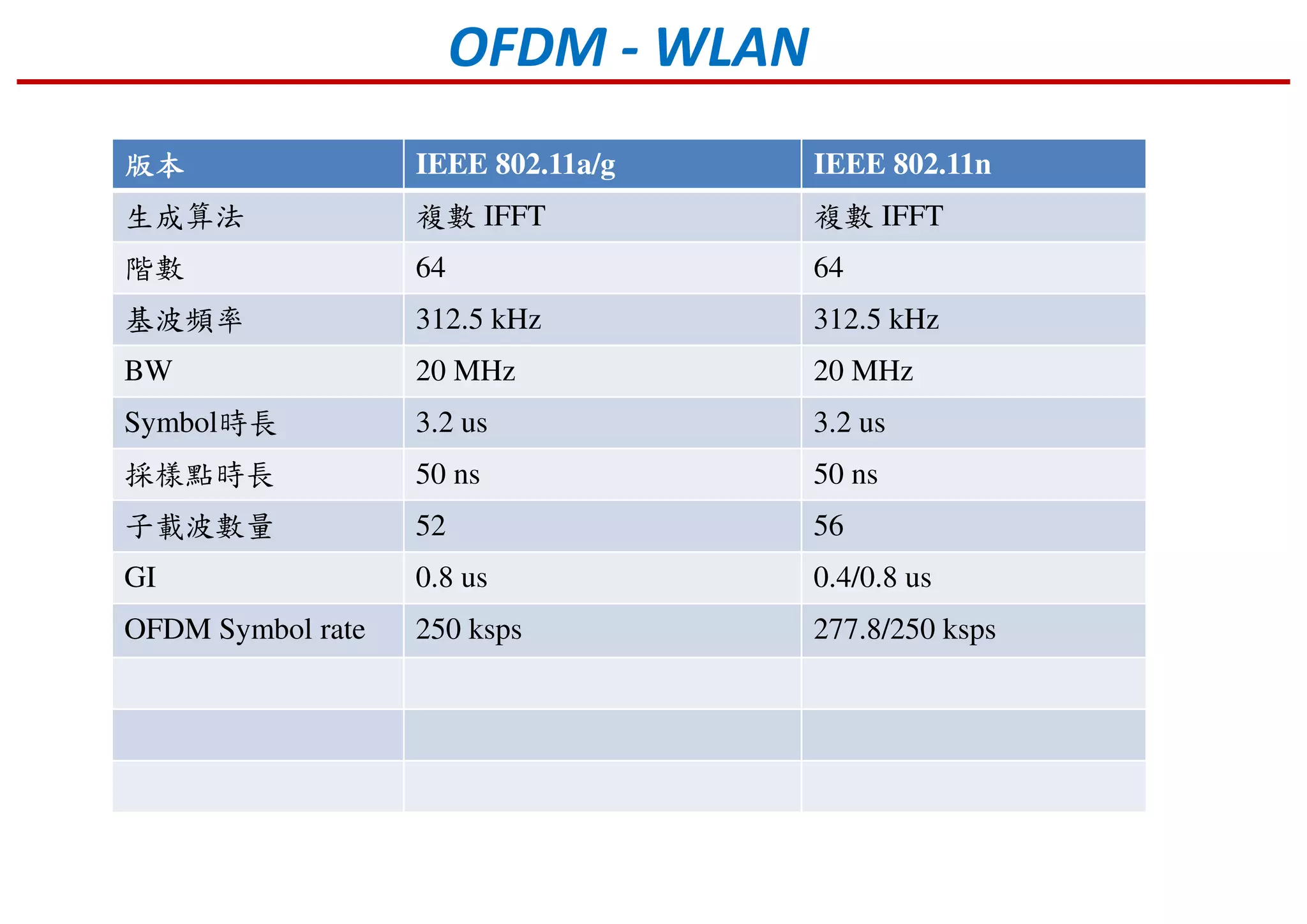
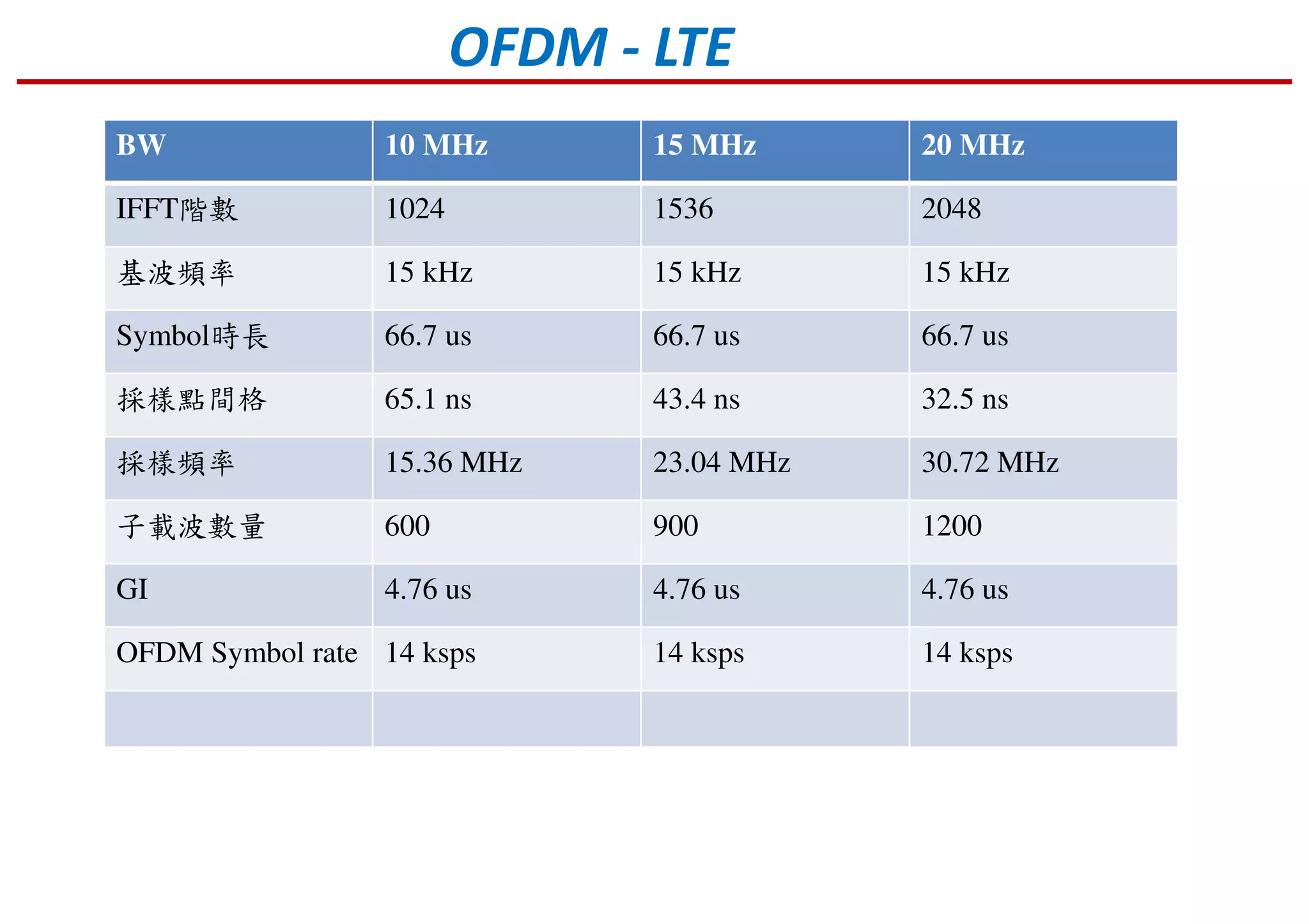
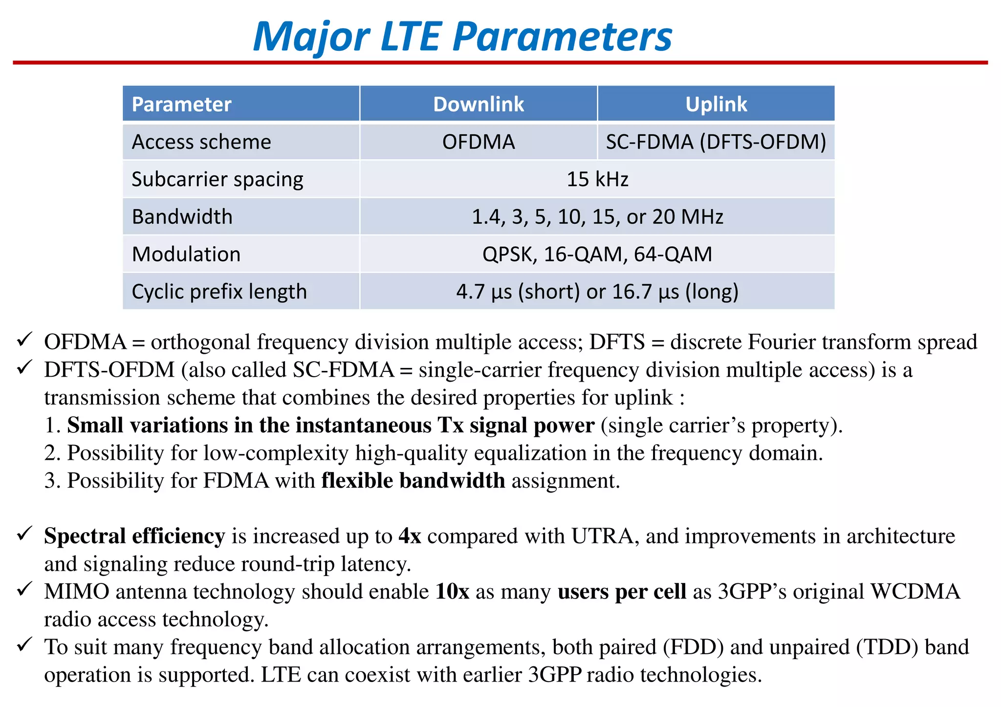
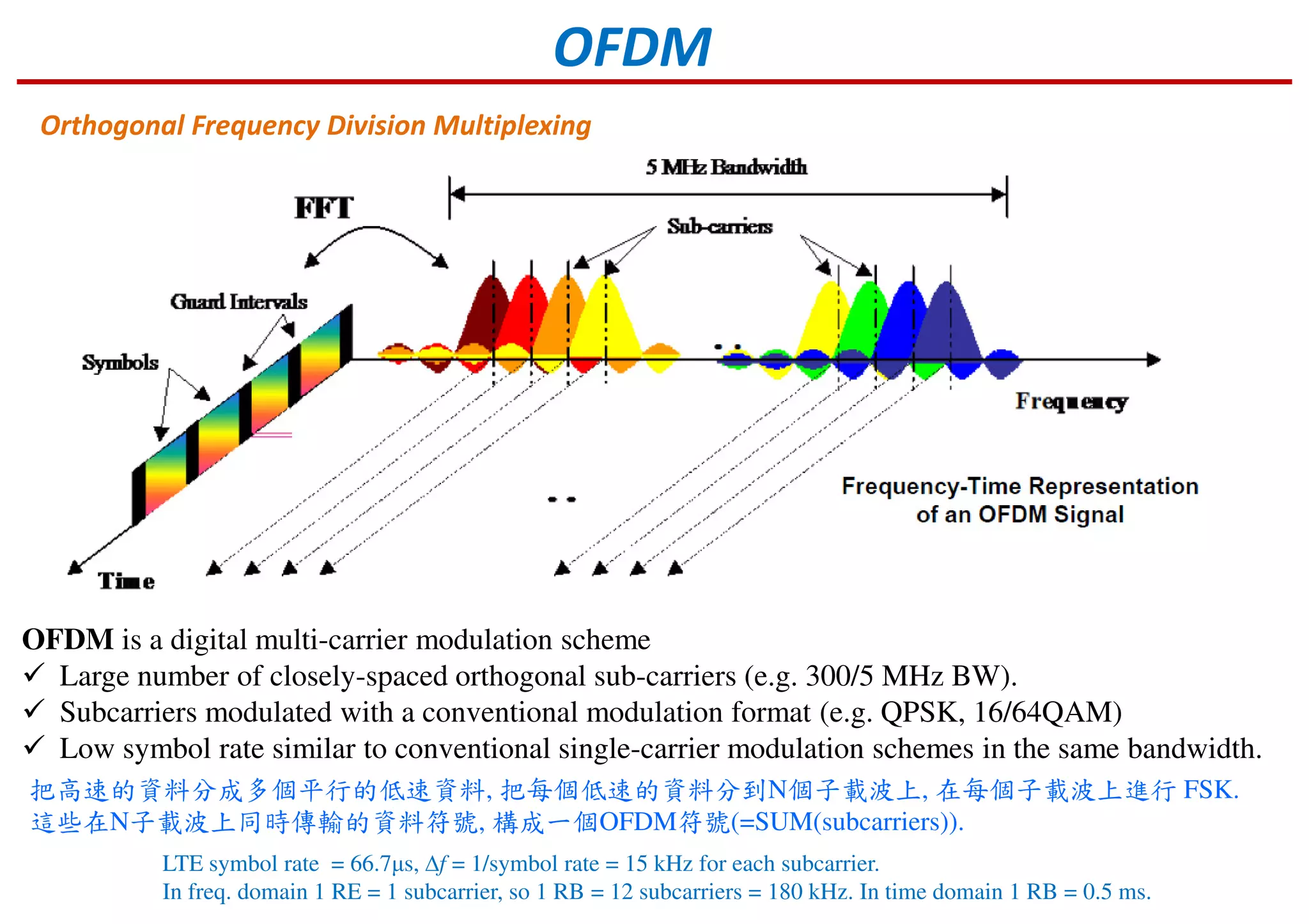
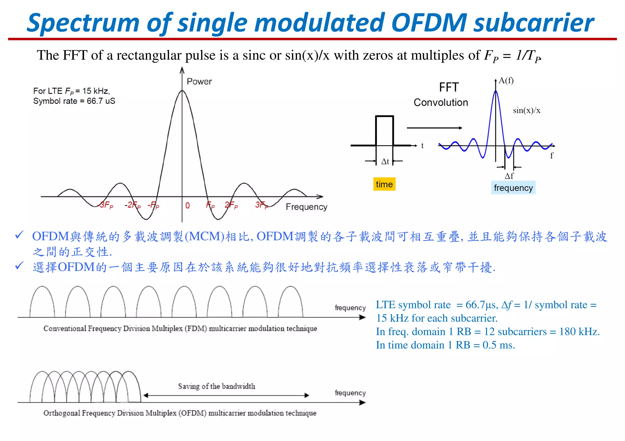
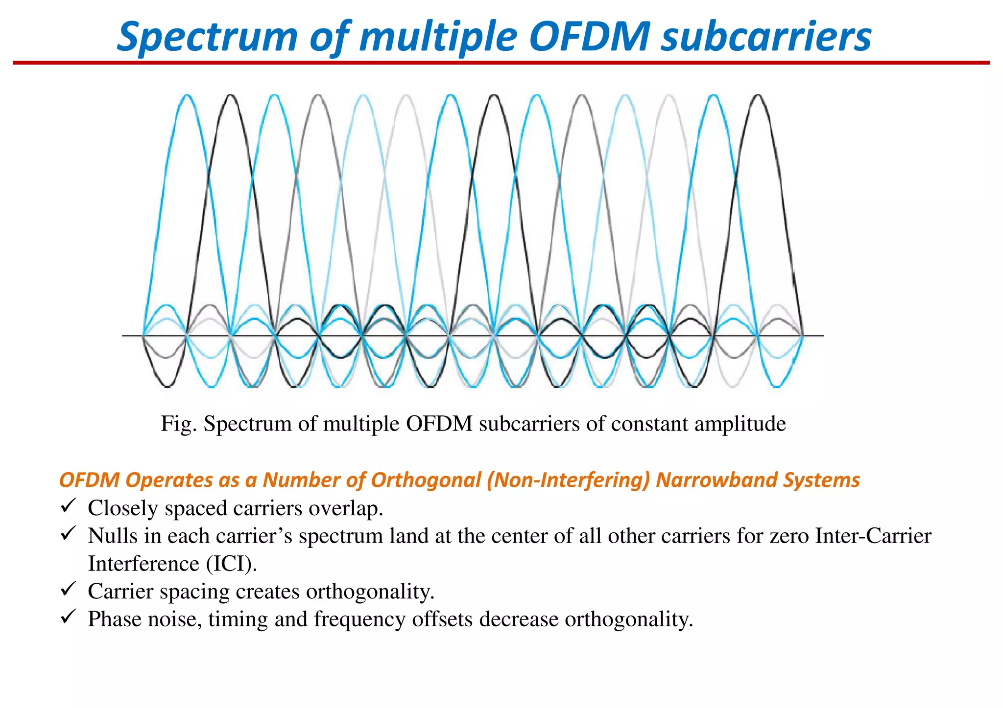
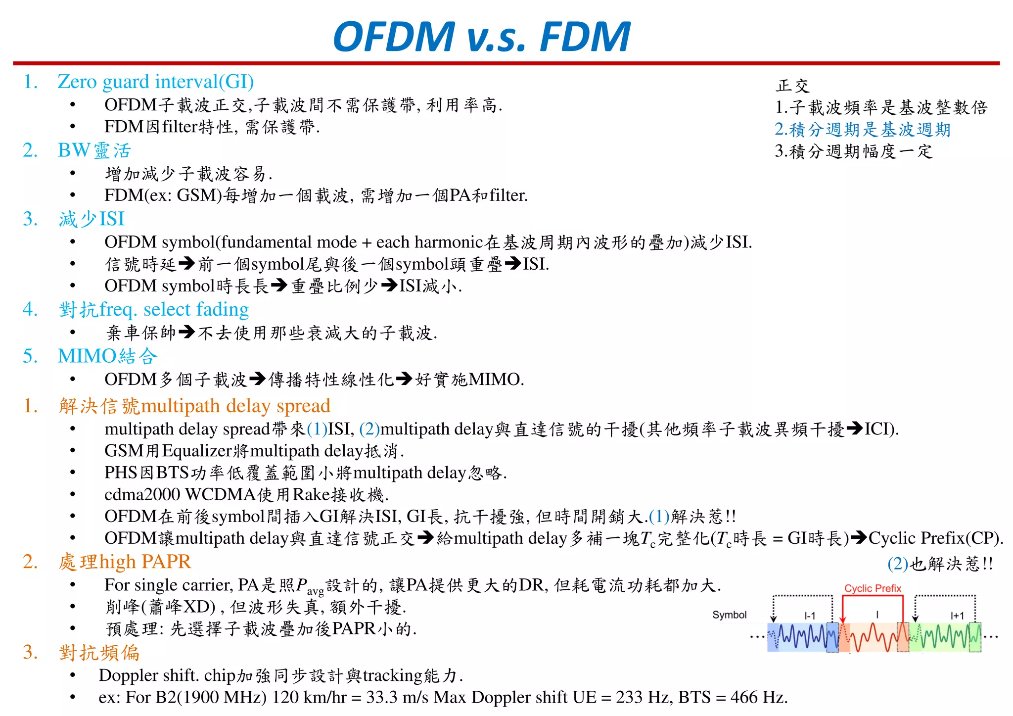
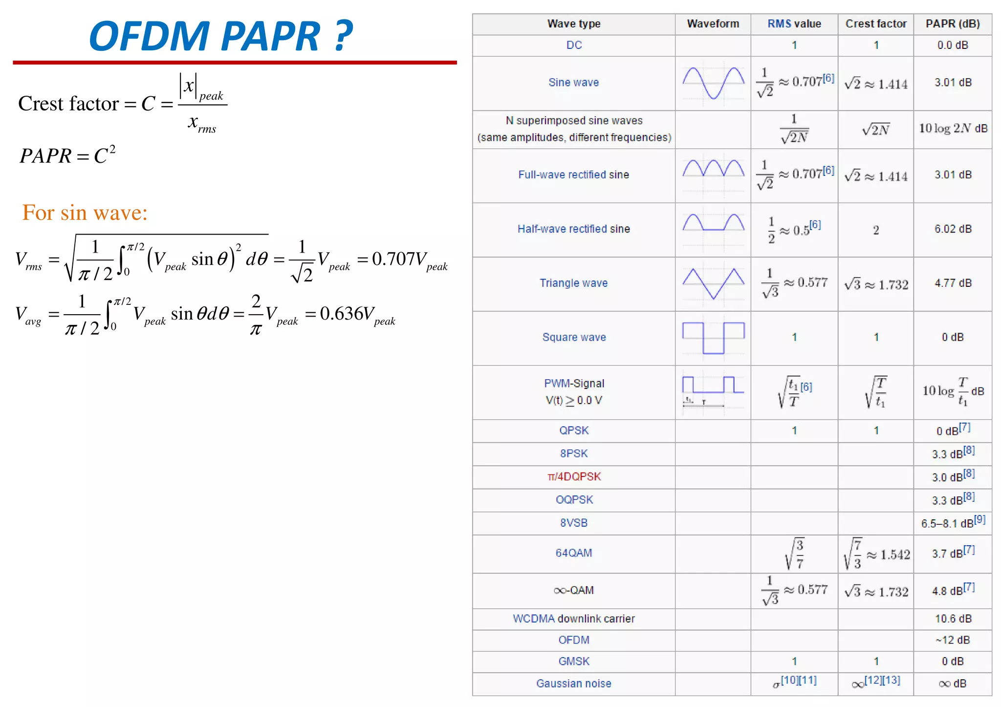
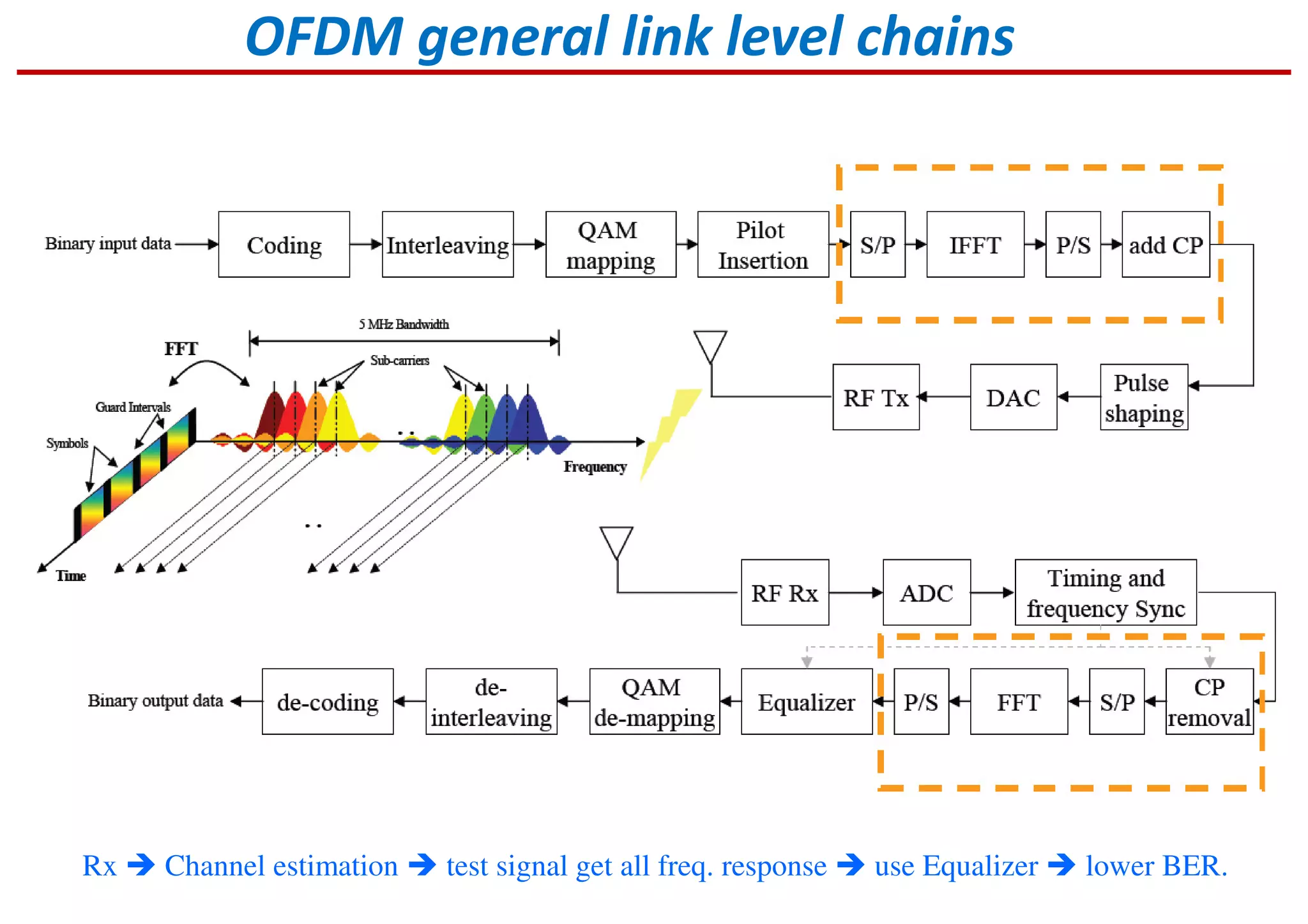
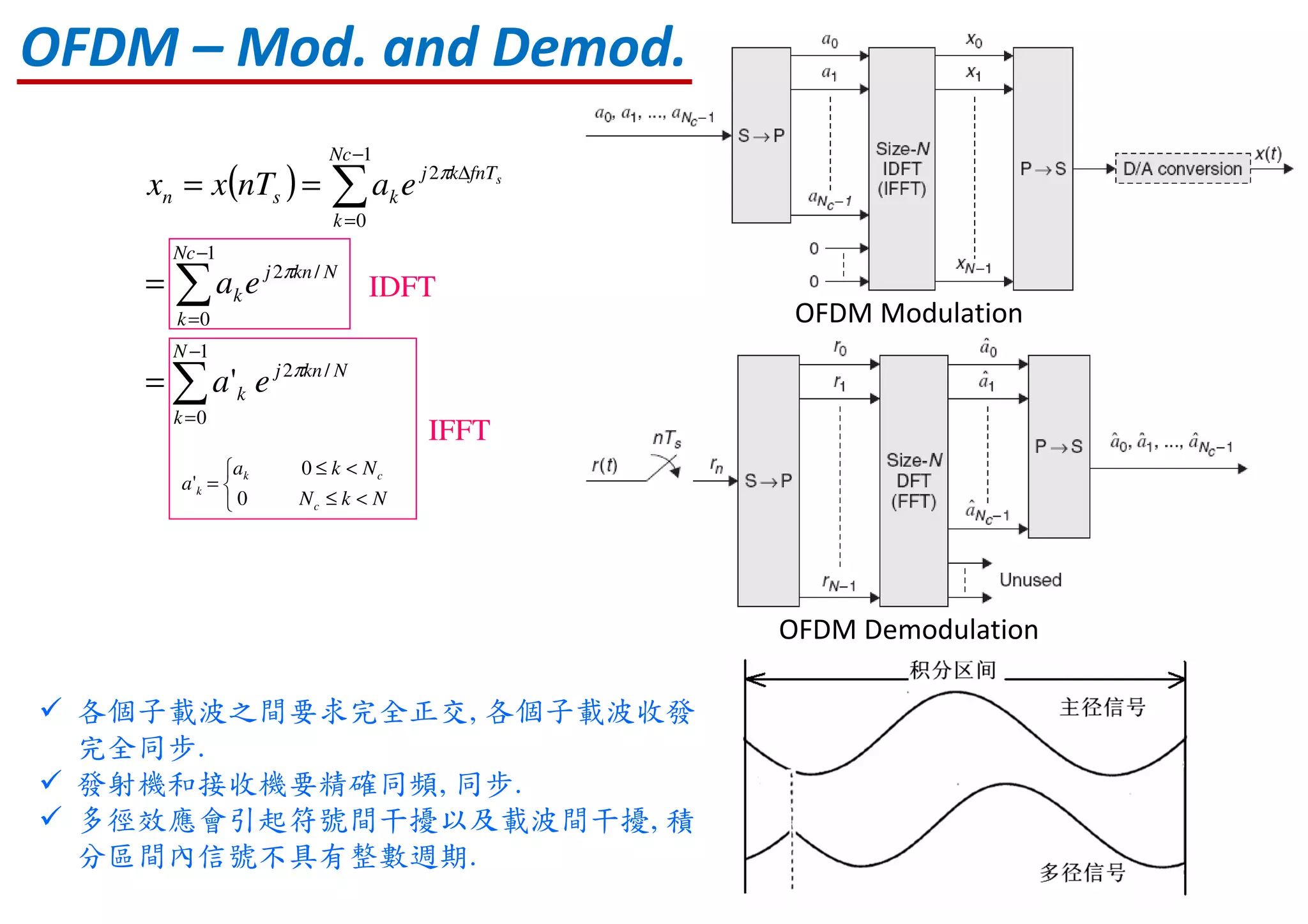
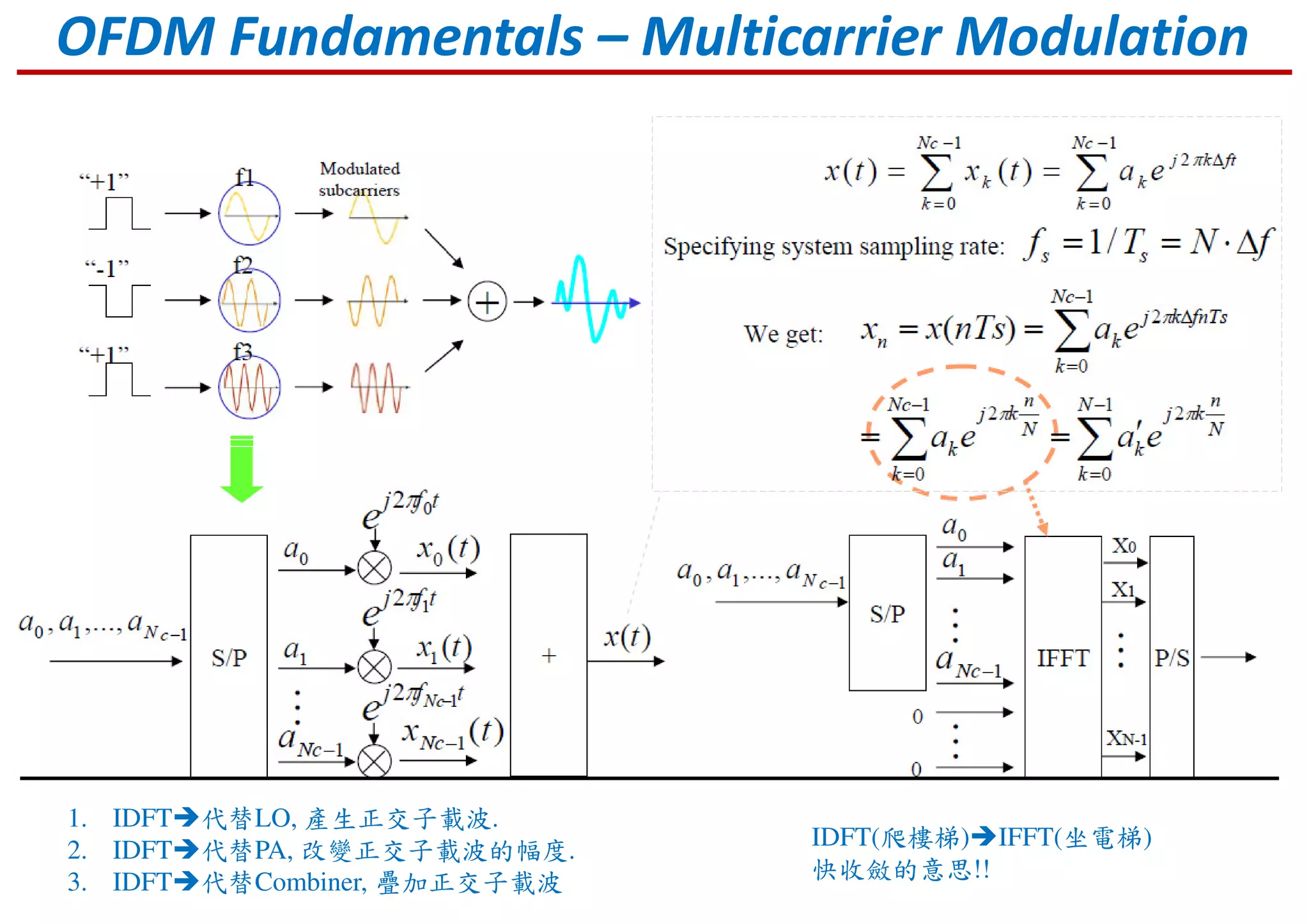
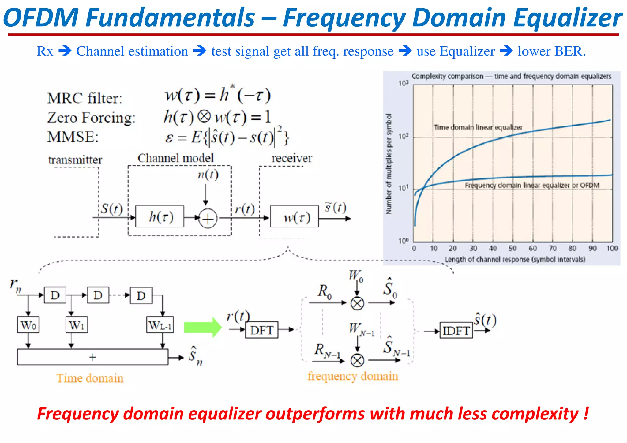
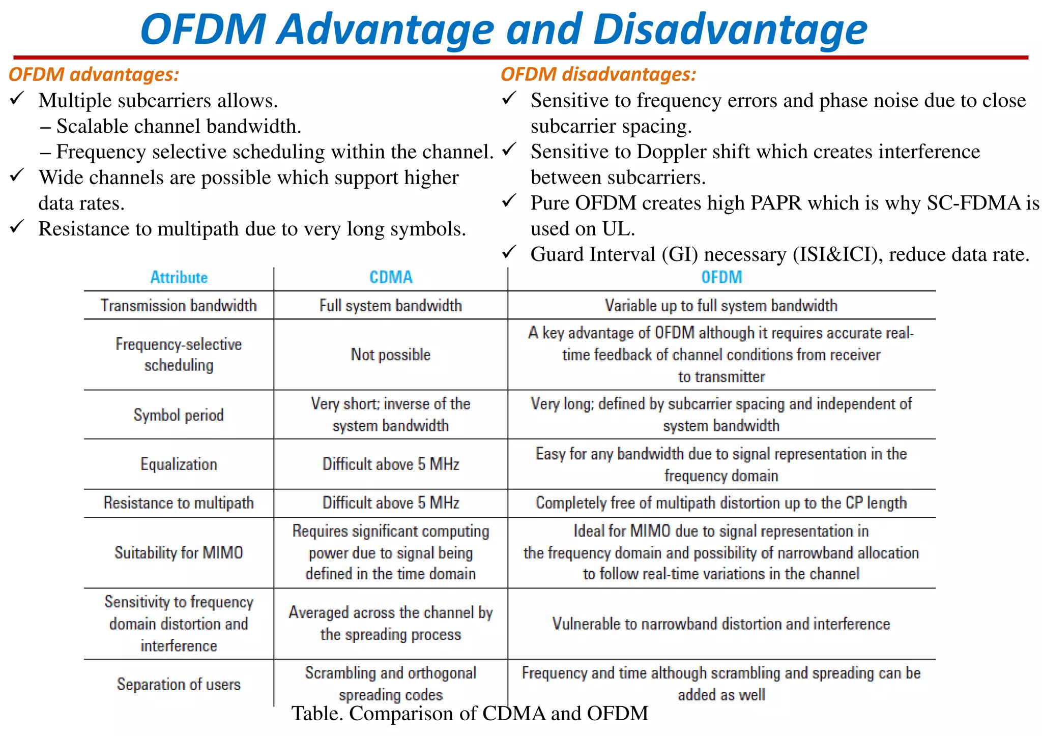
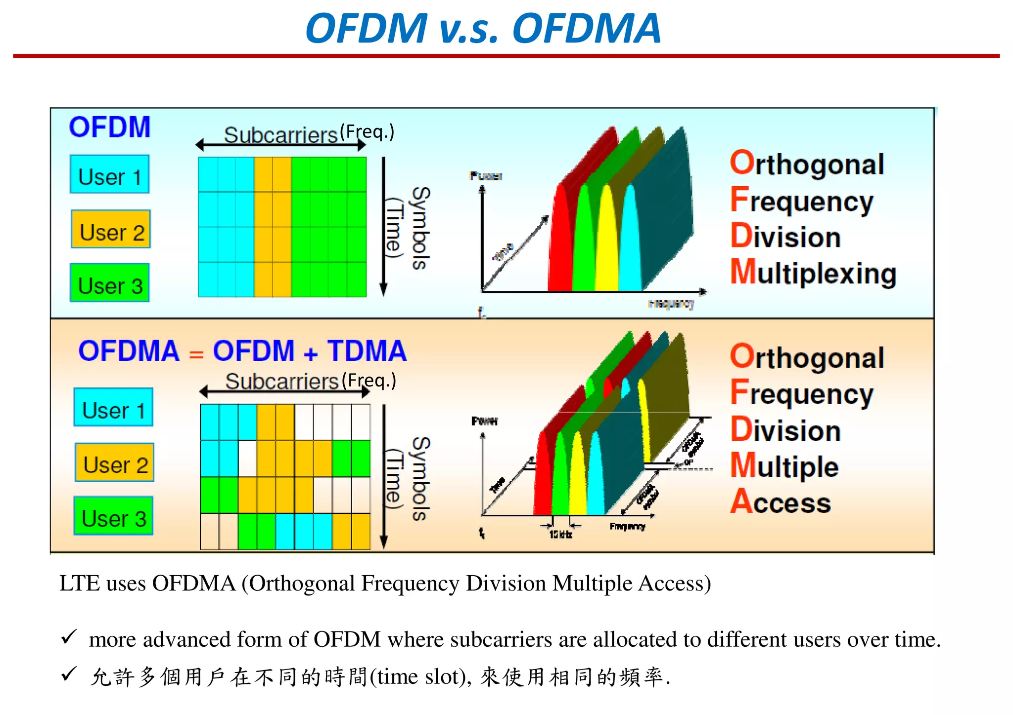
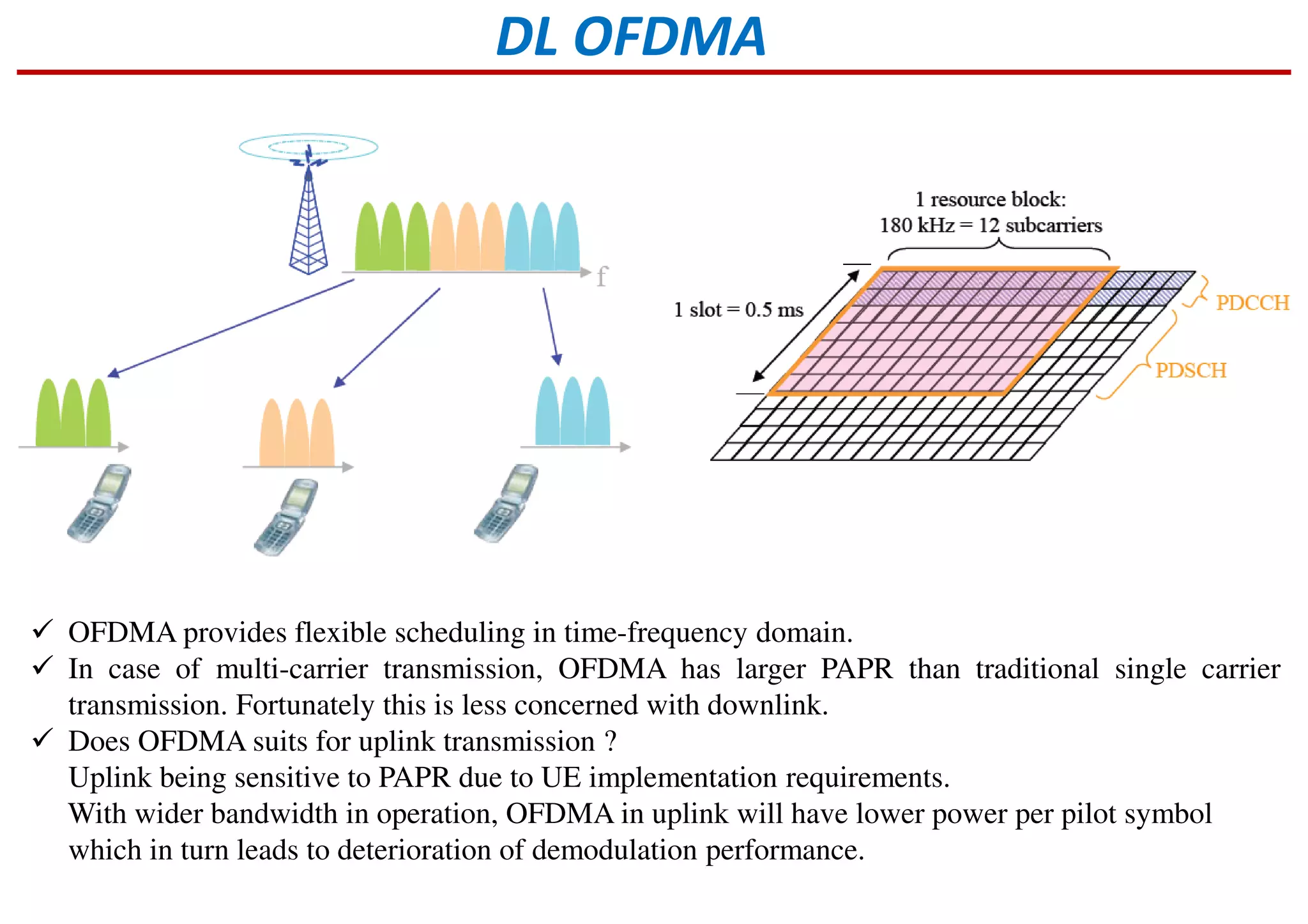
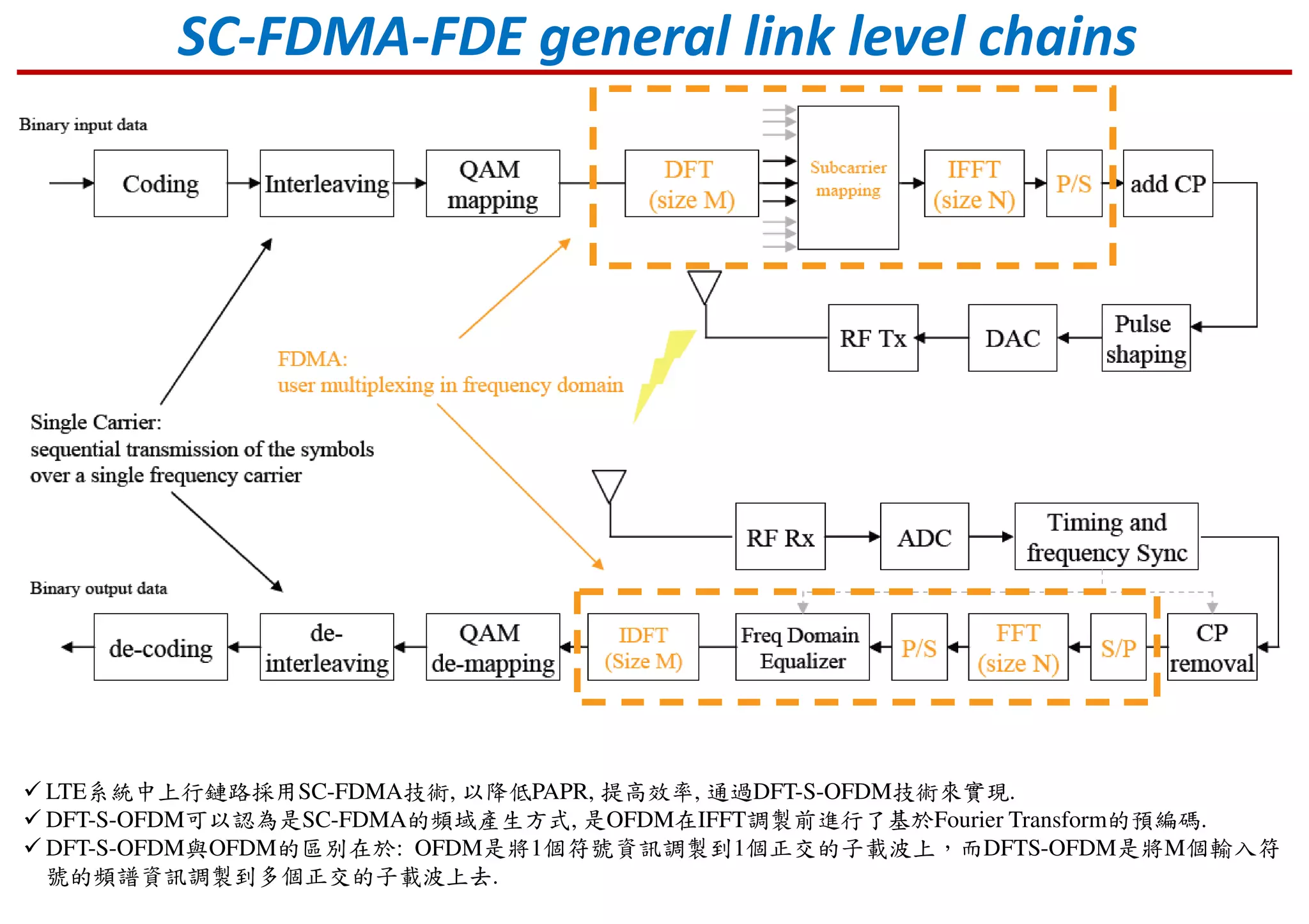
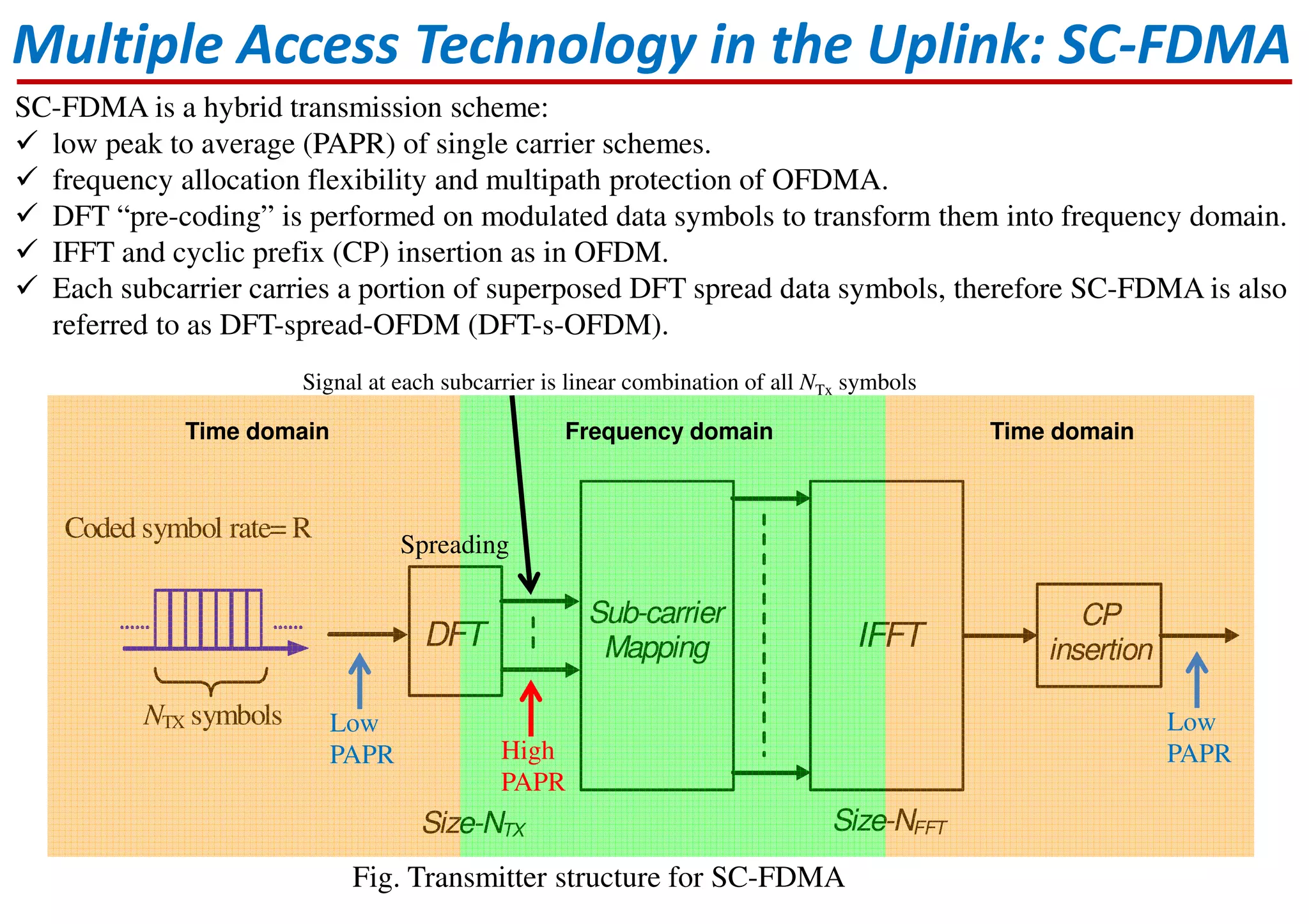
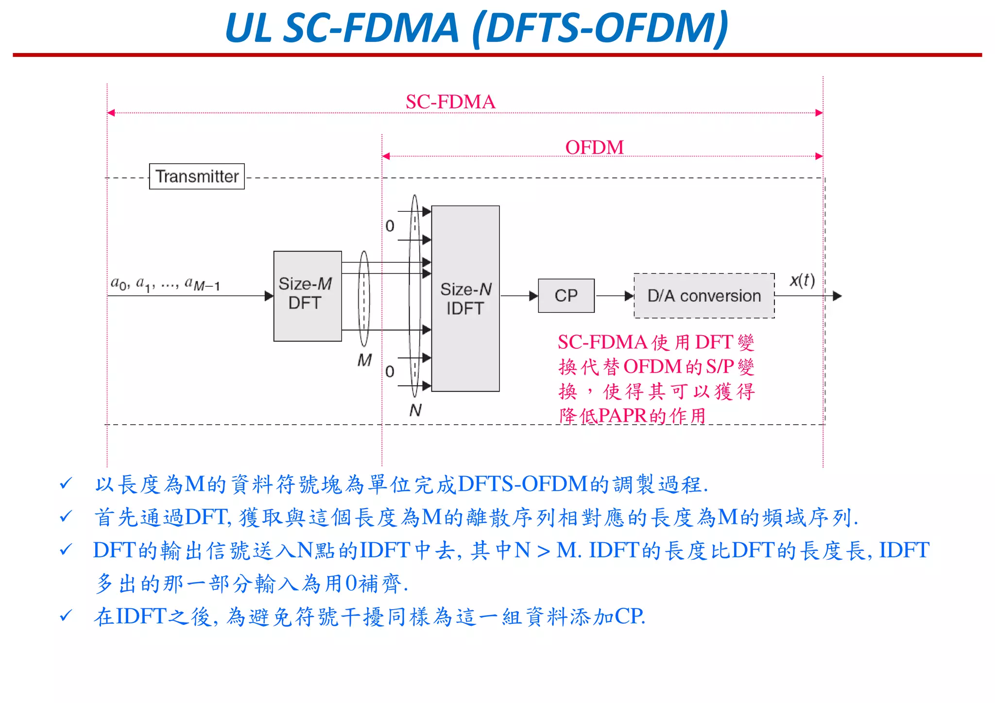
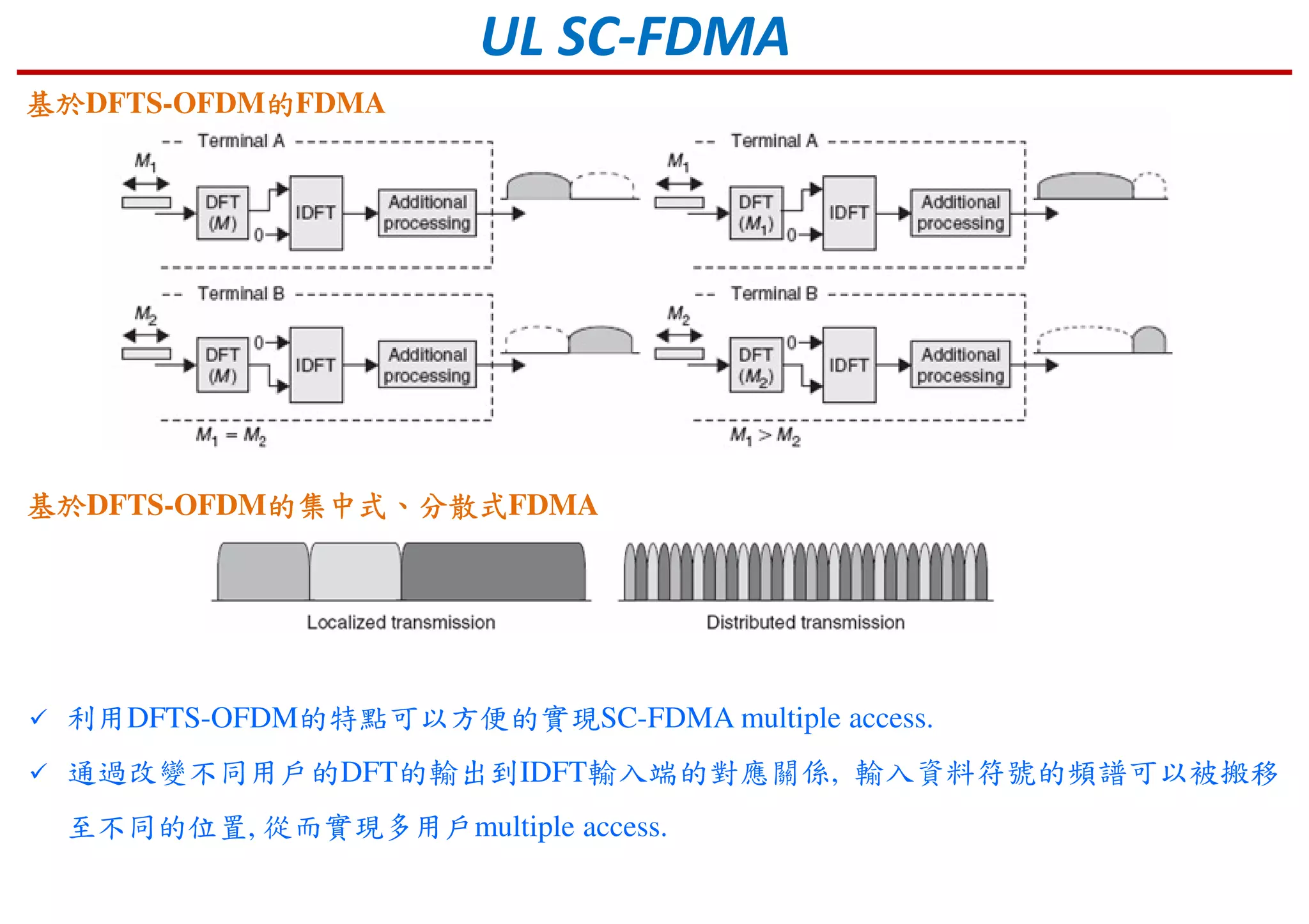
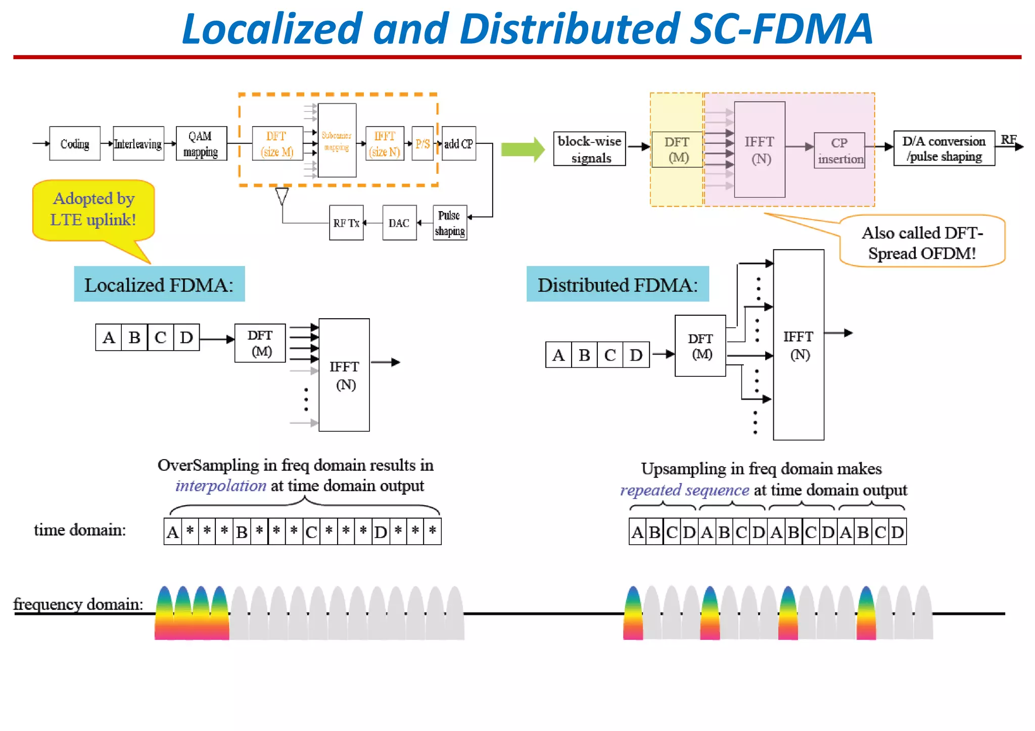
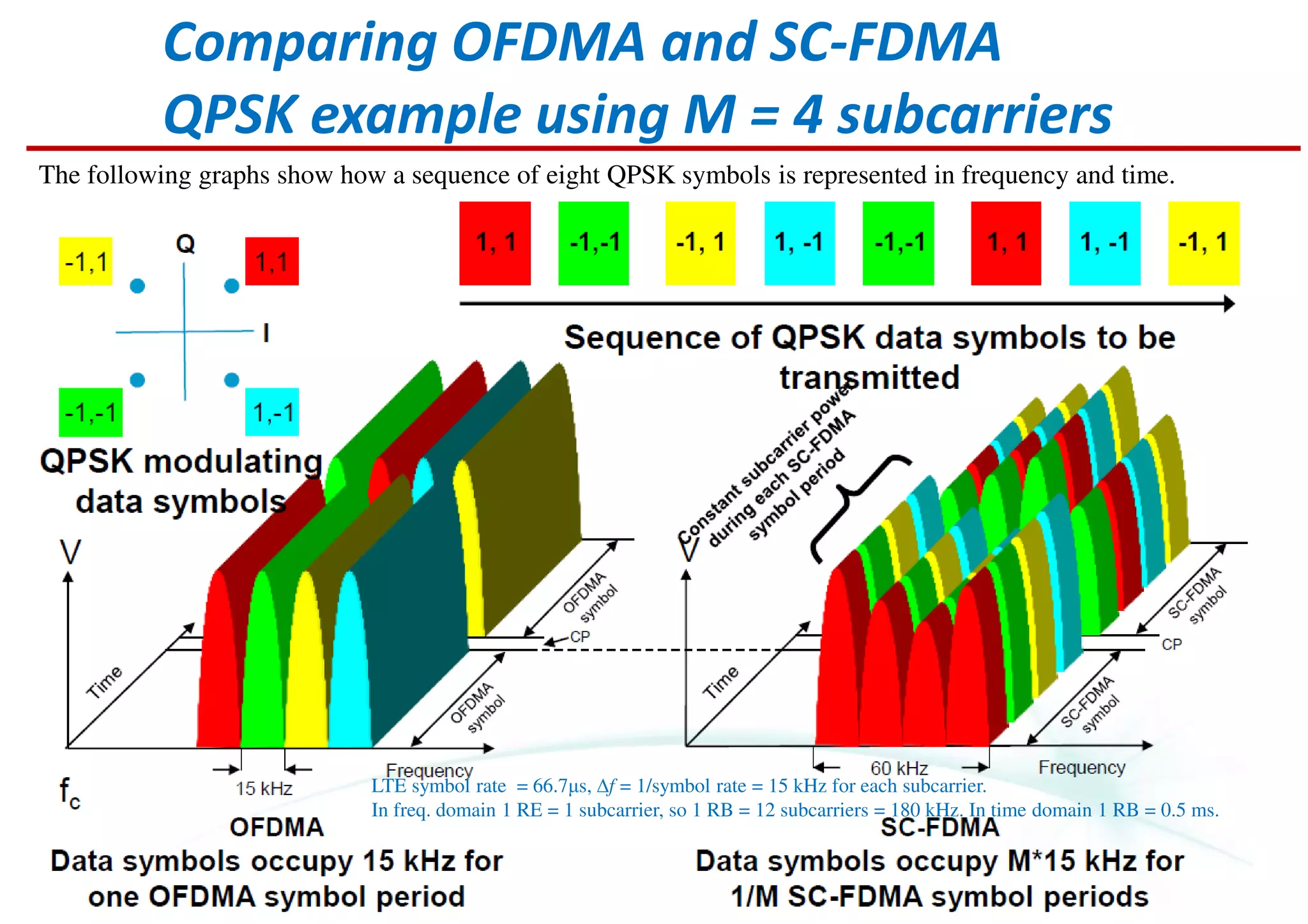
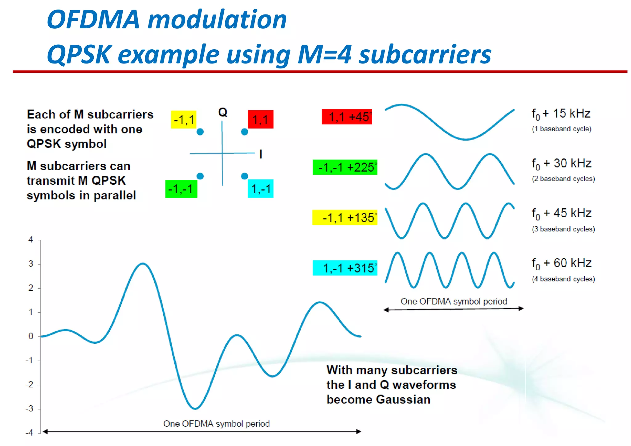
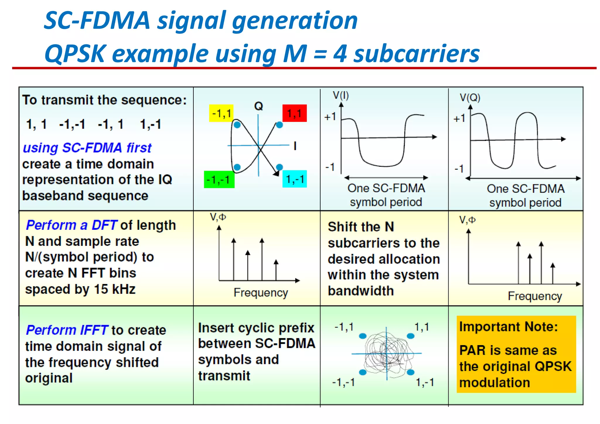
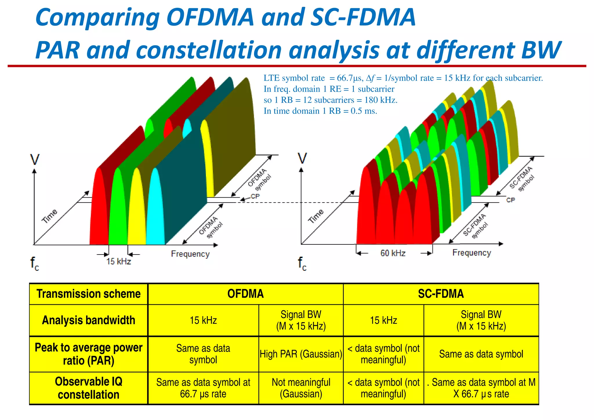
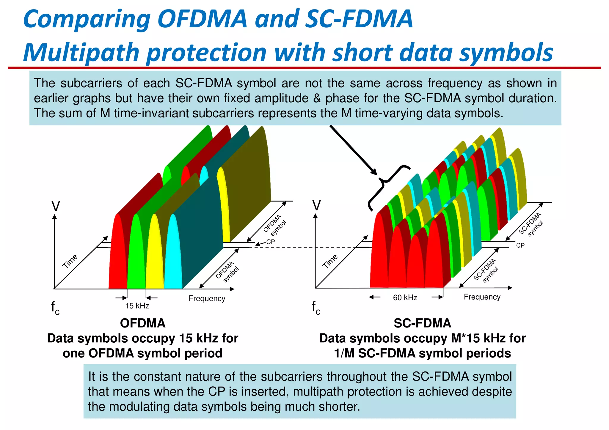
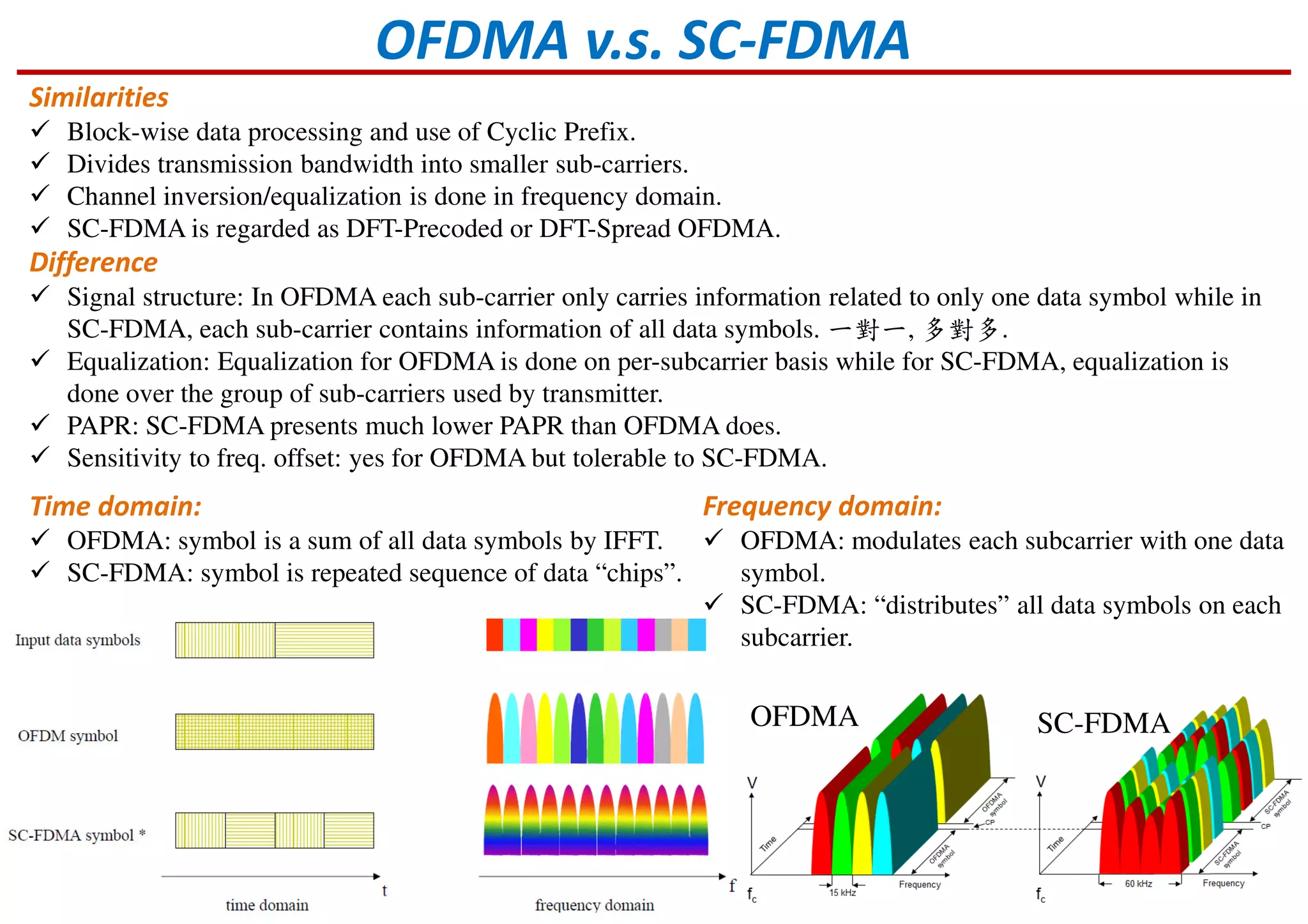
Overview of OFDM technology and its advantages in avoiding multipath delay and interference.
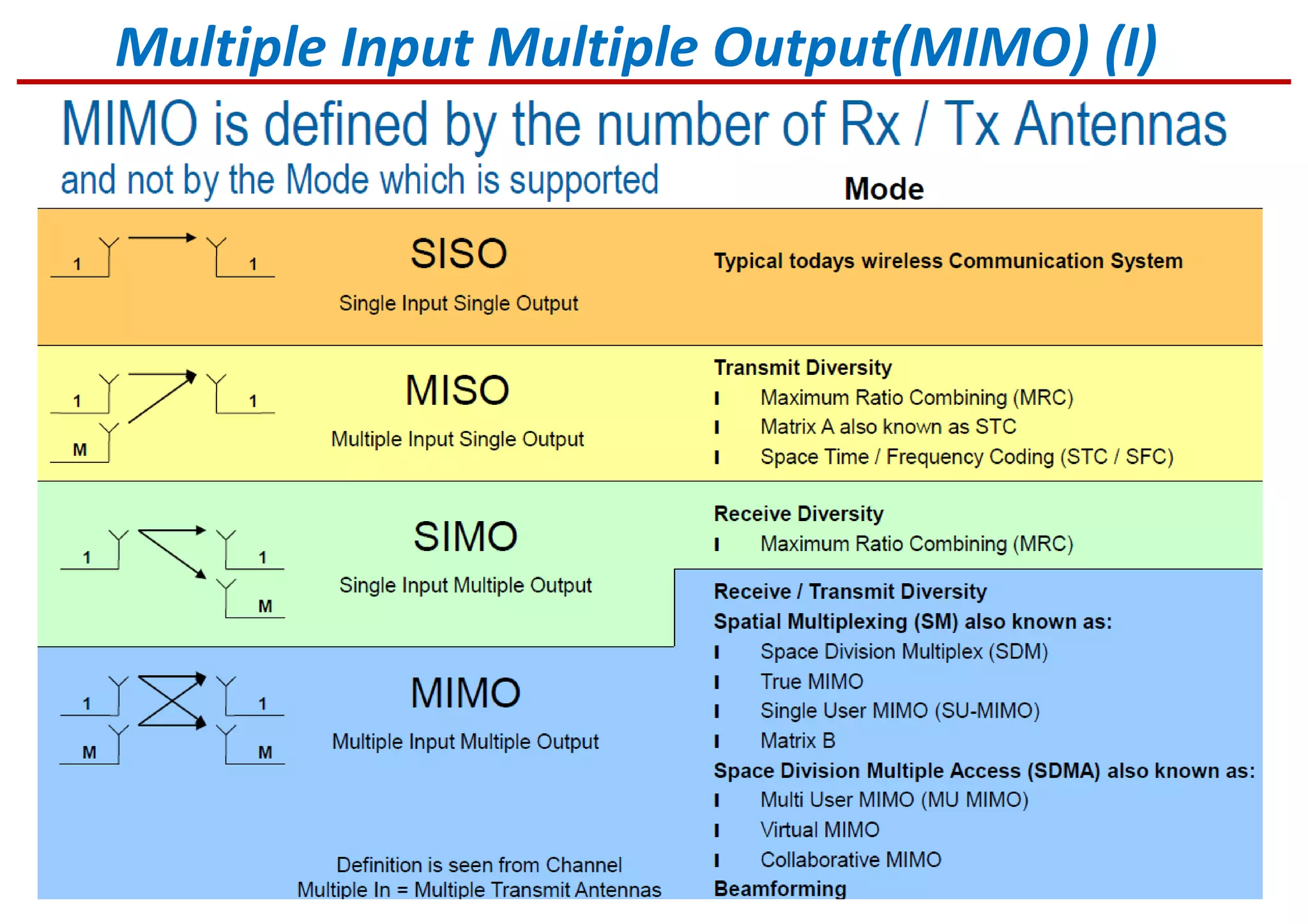
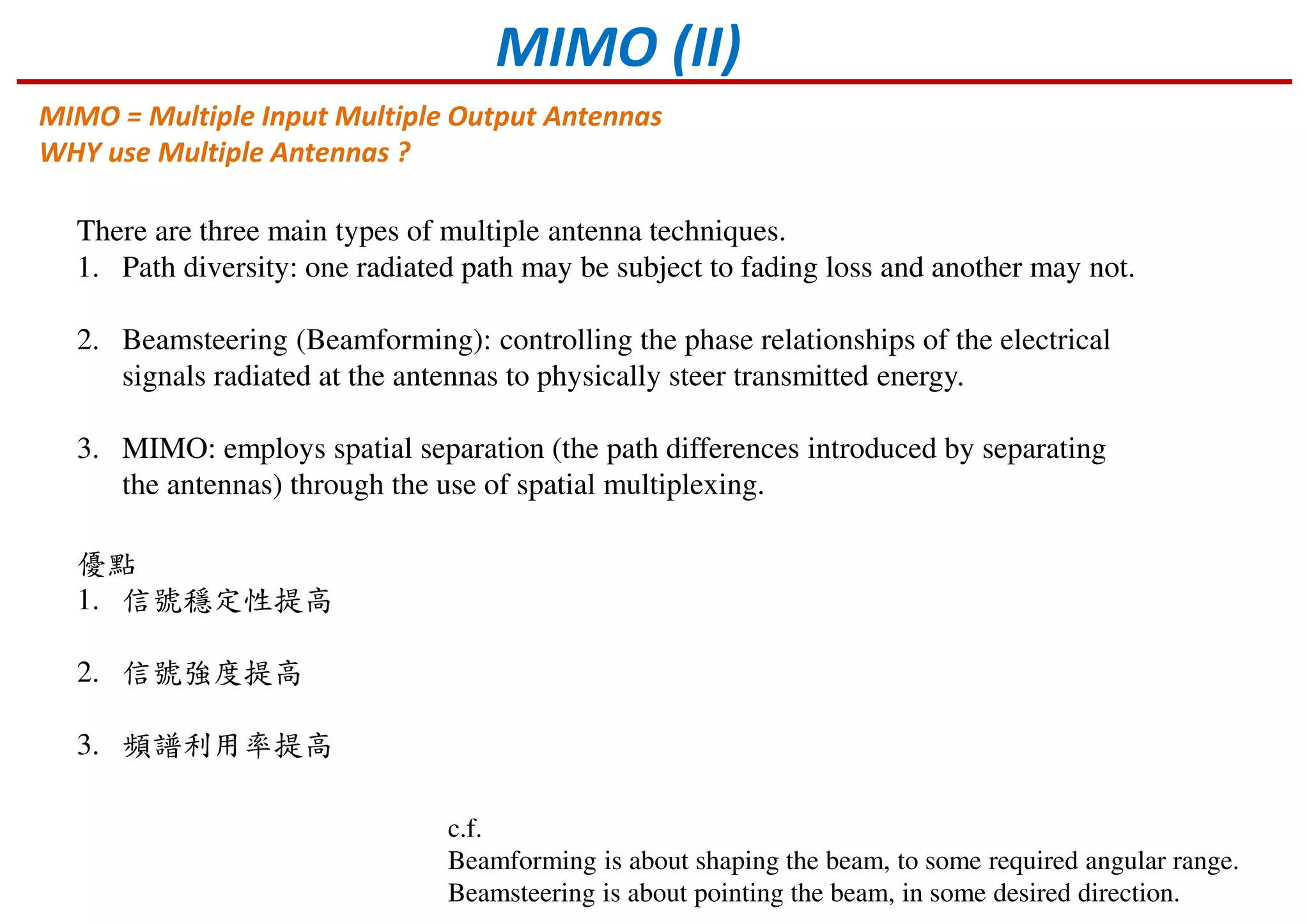
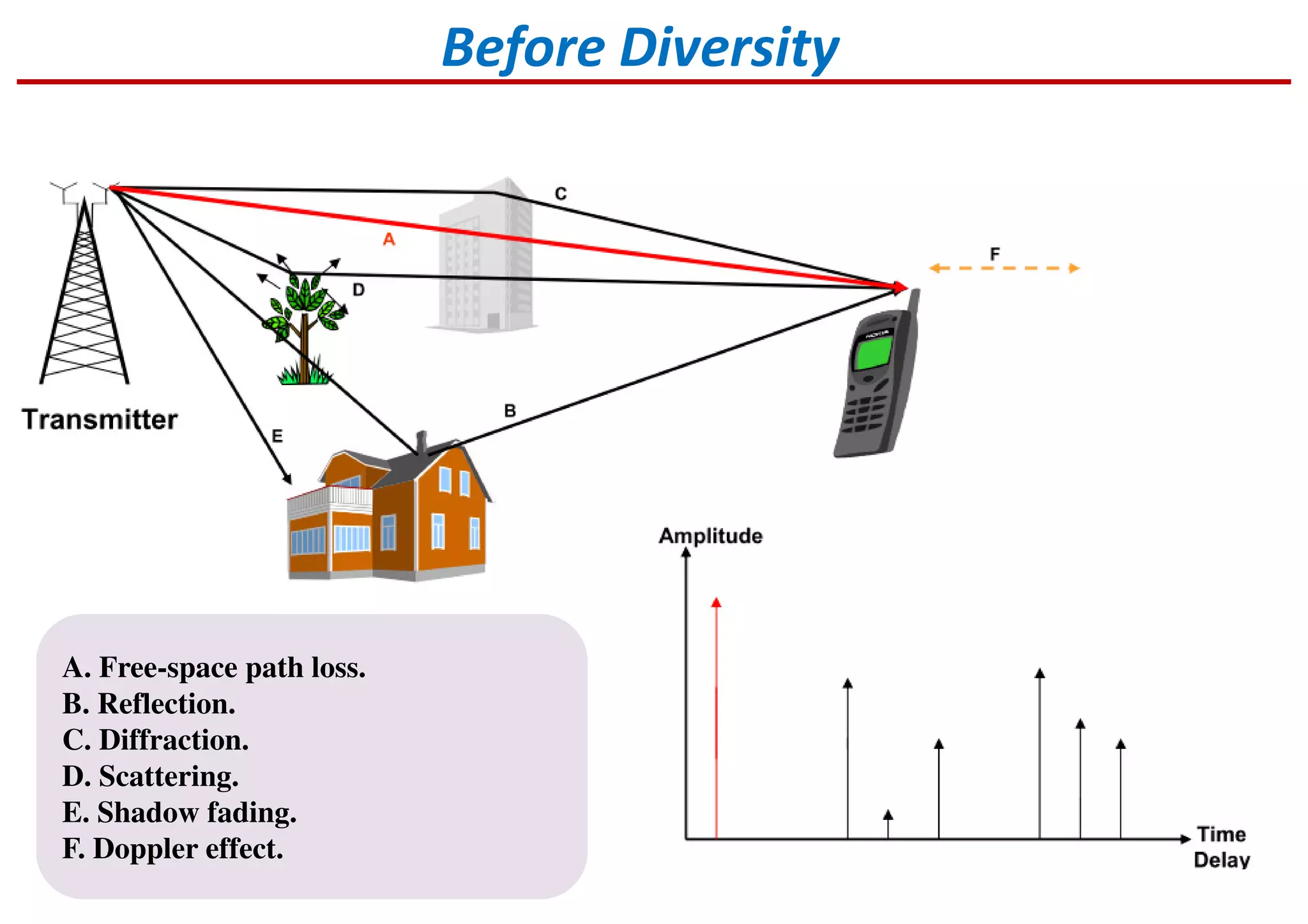
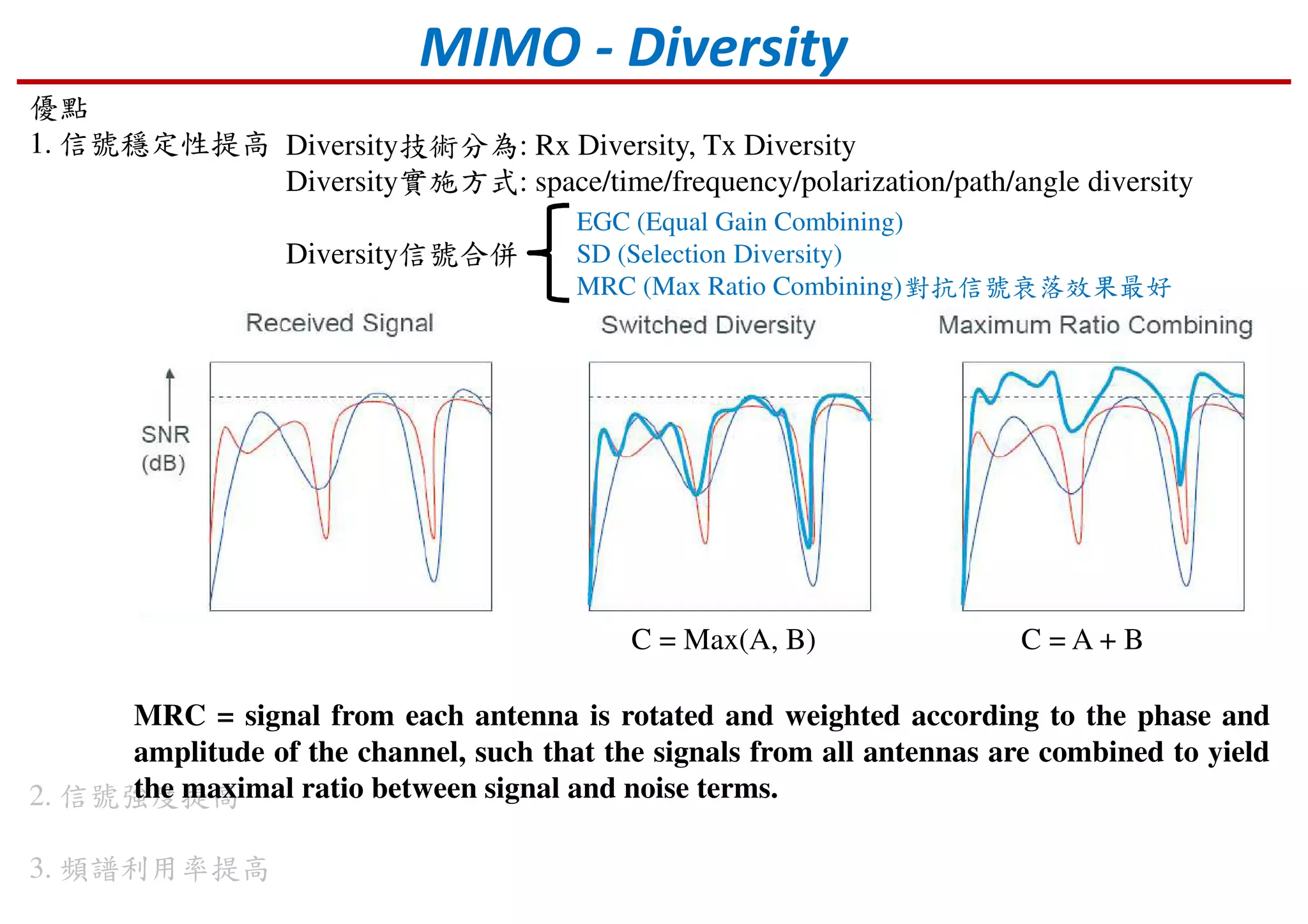
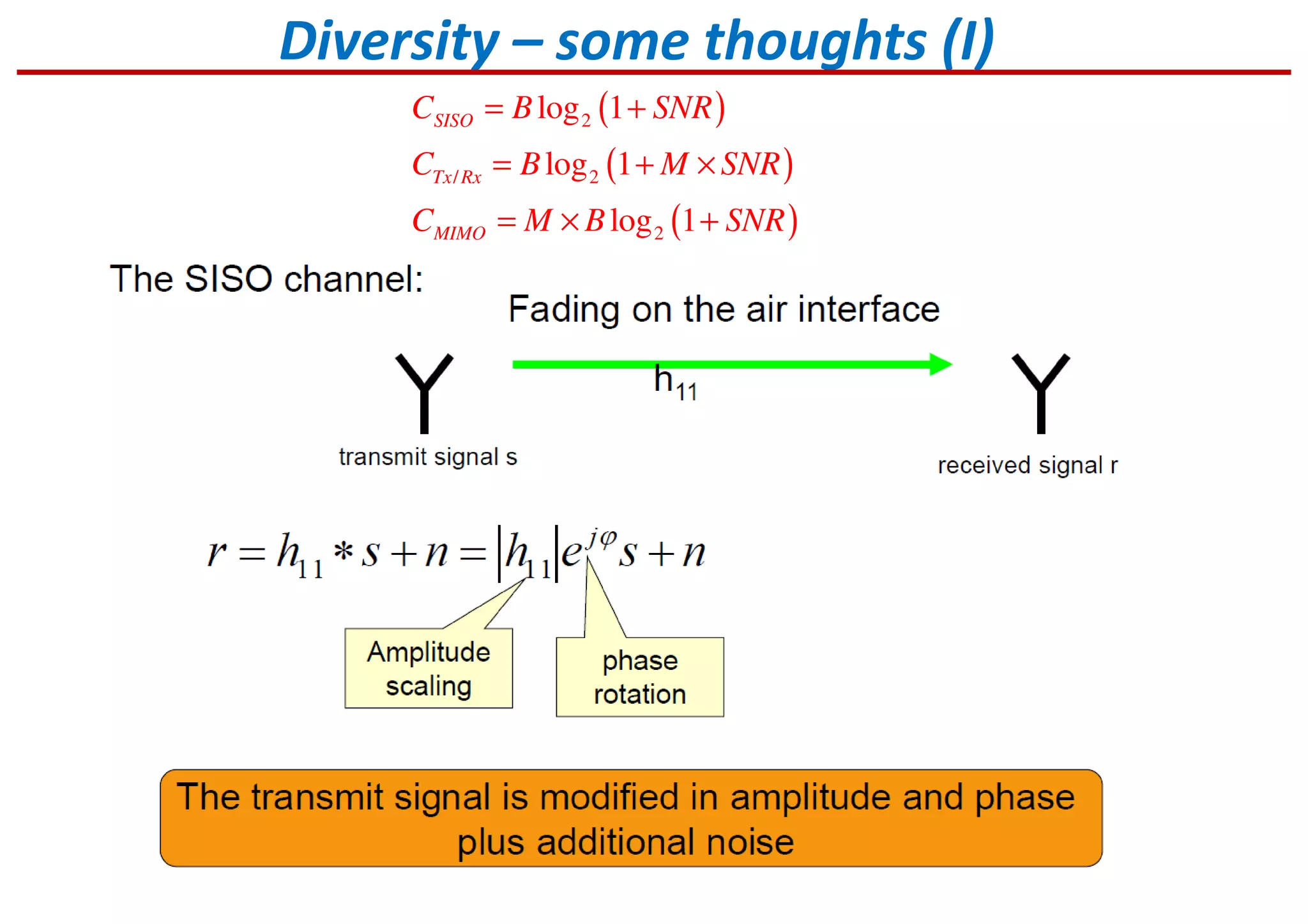
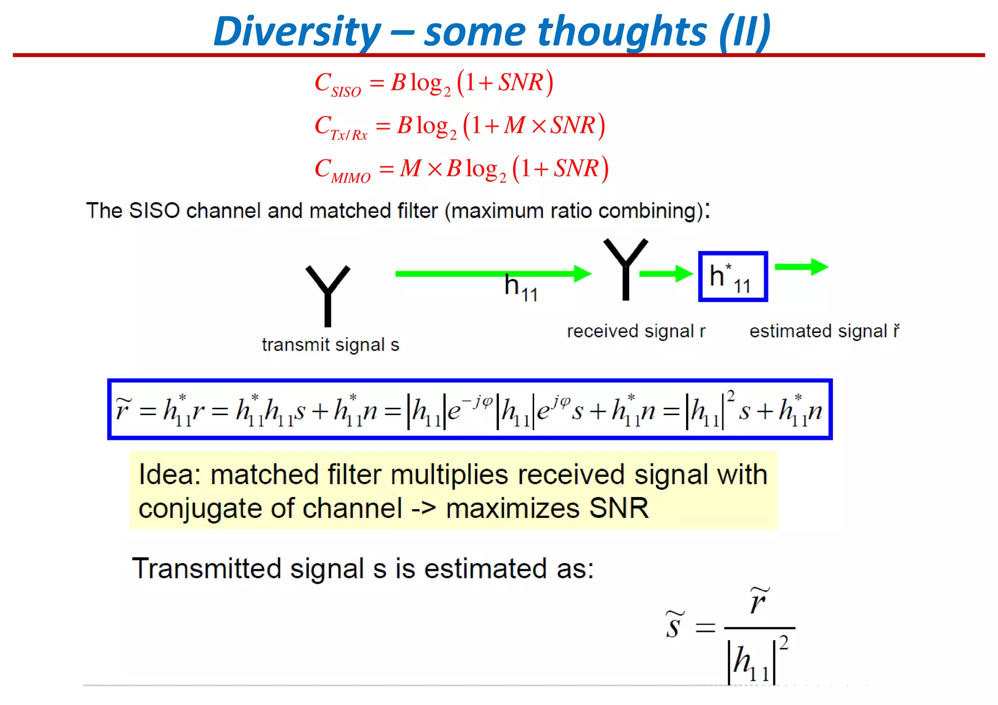
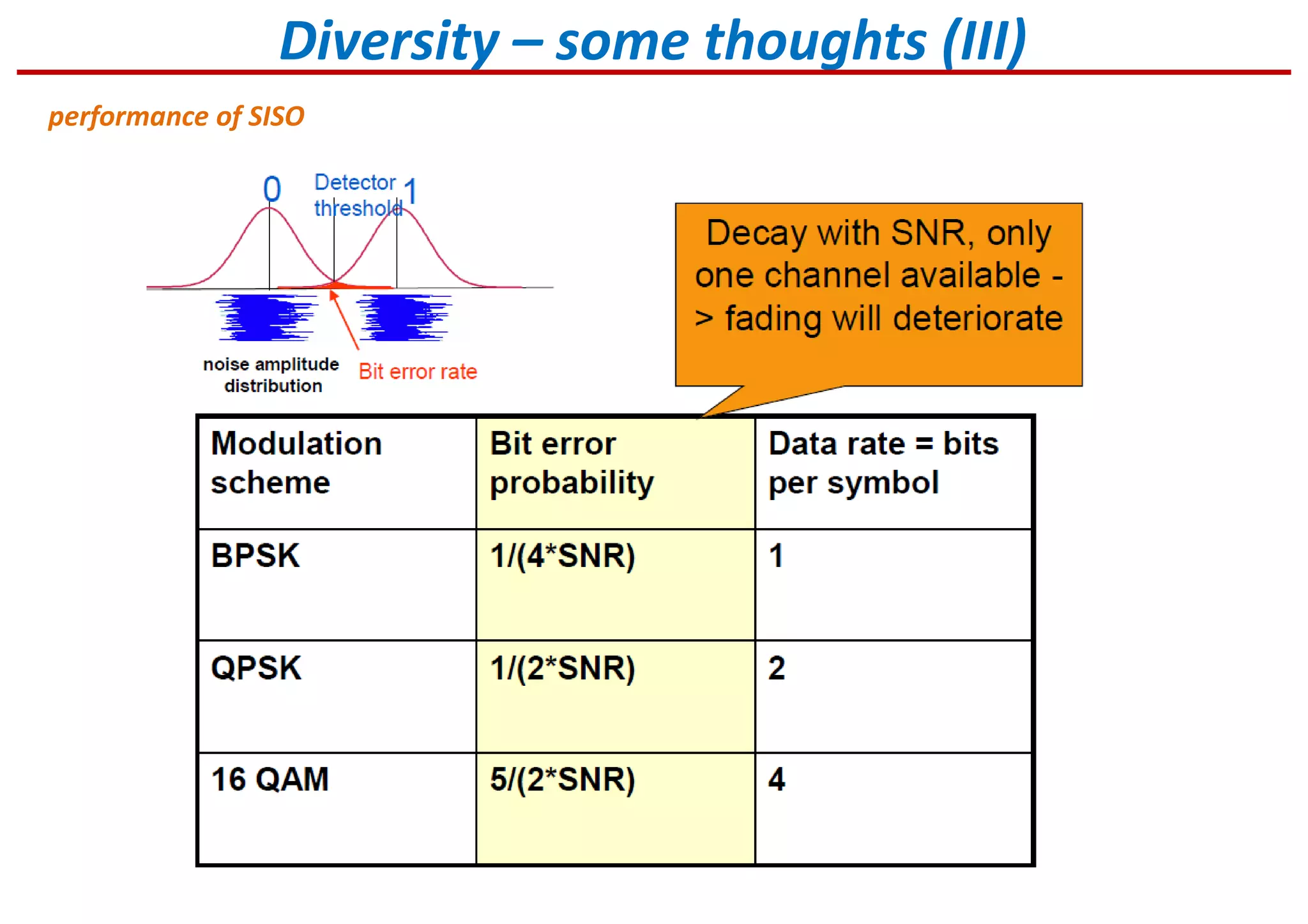
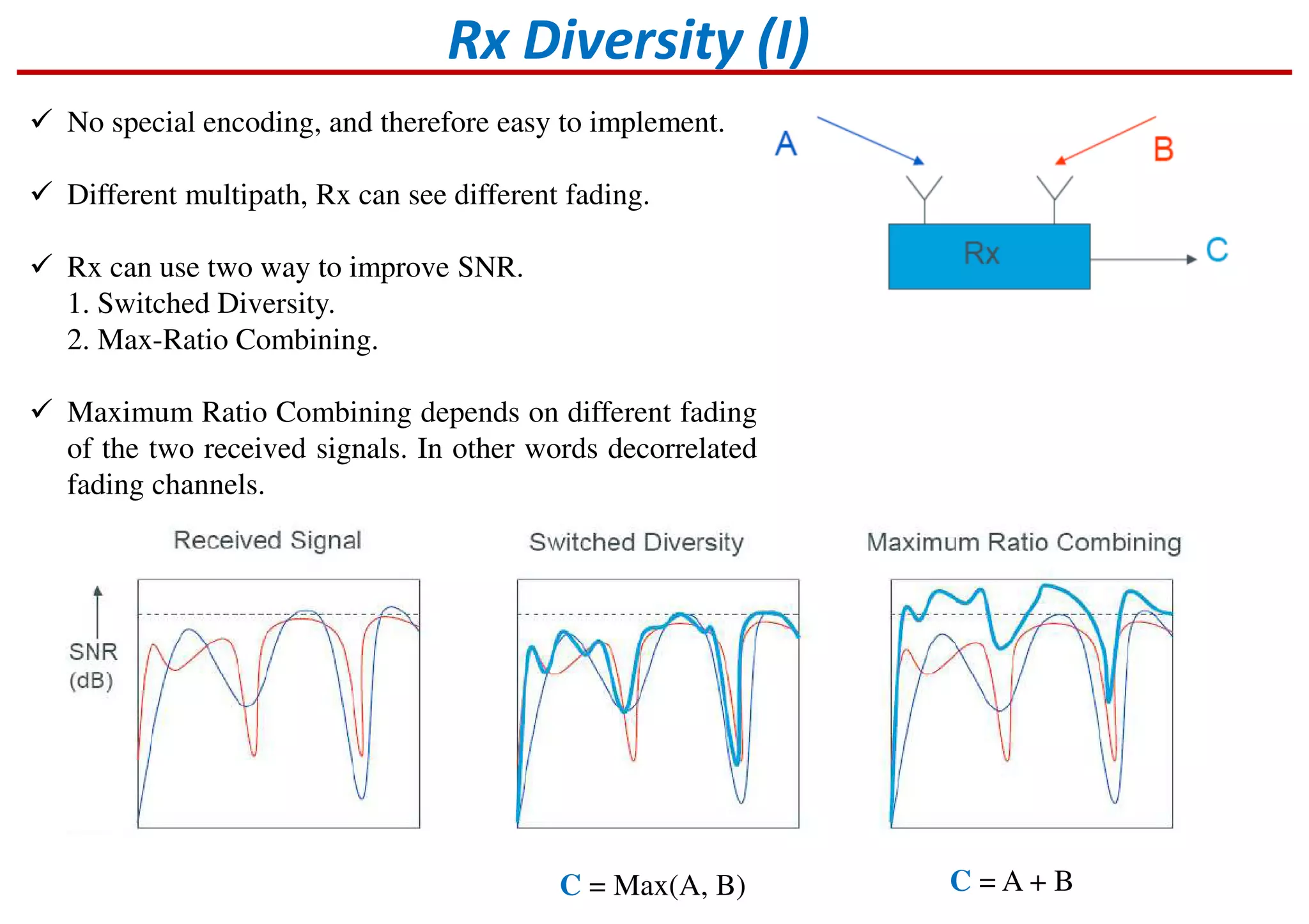
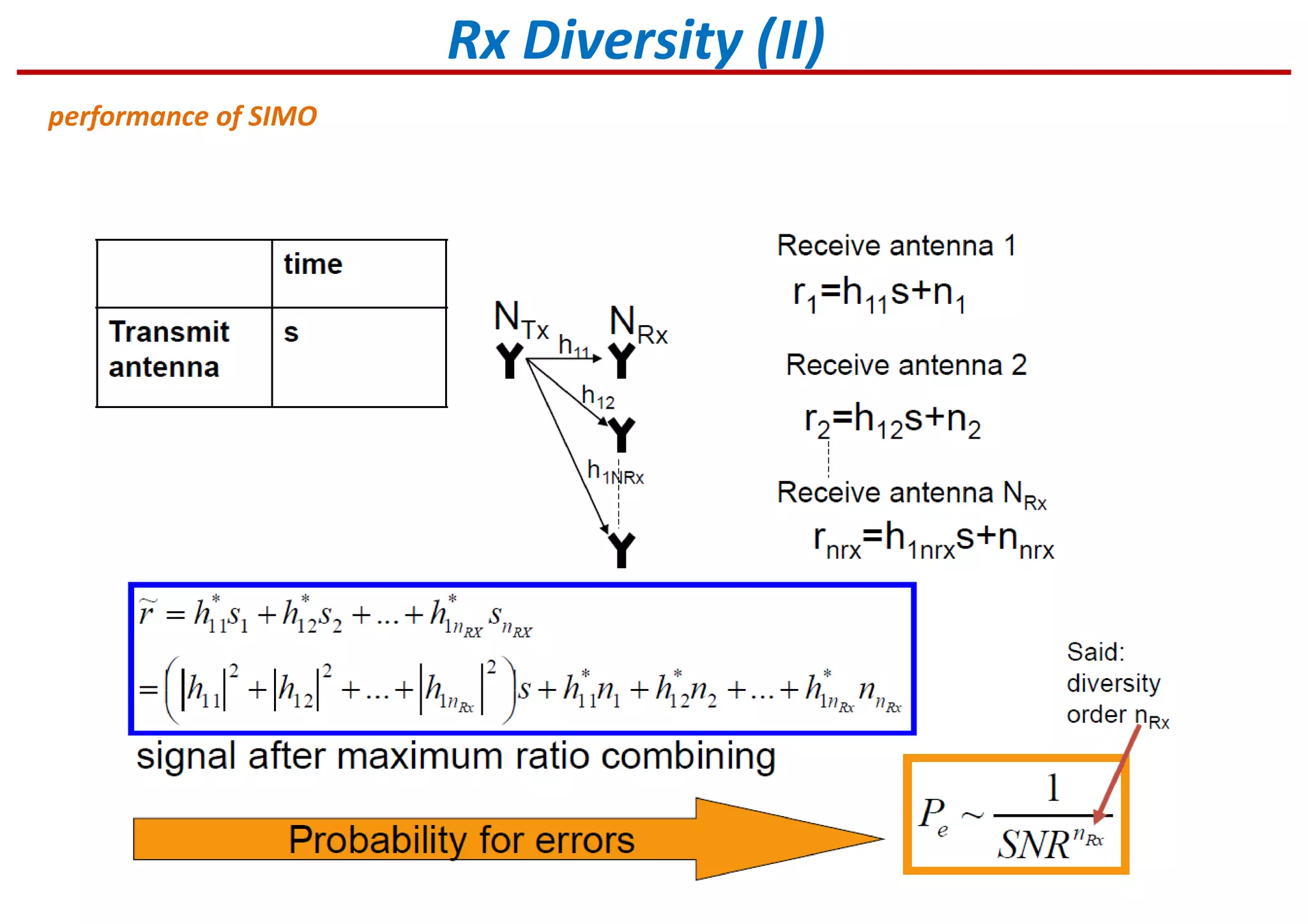
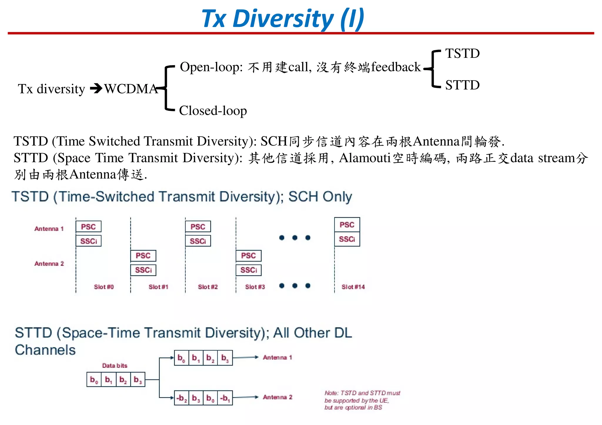
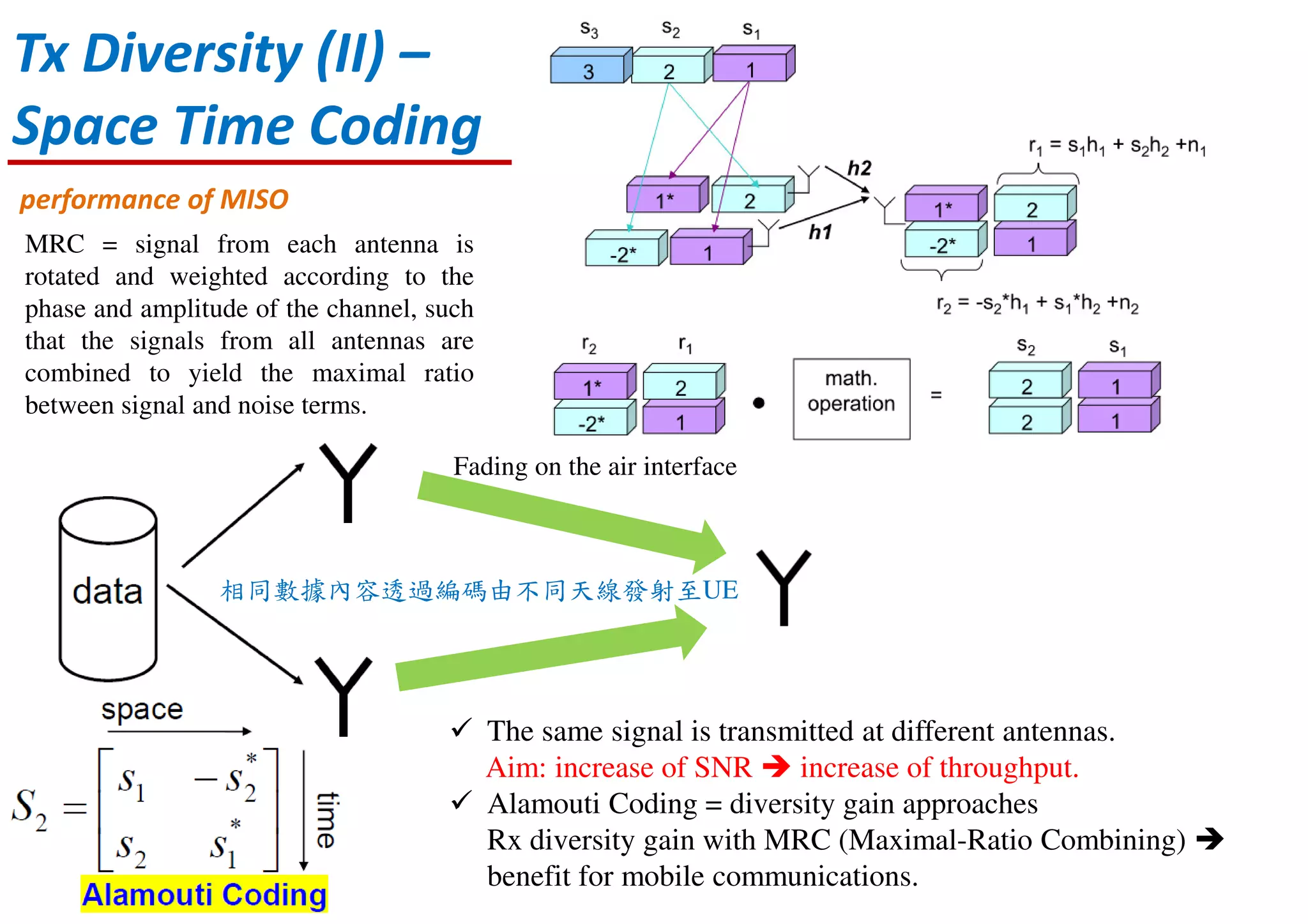
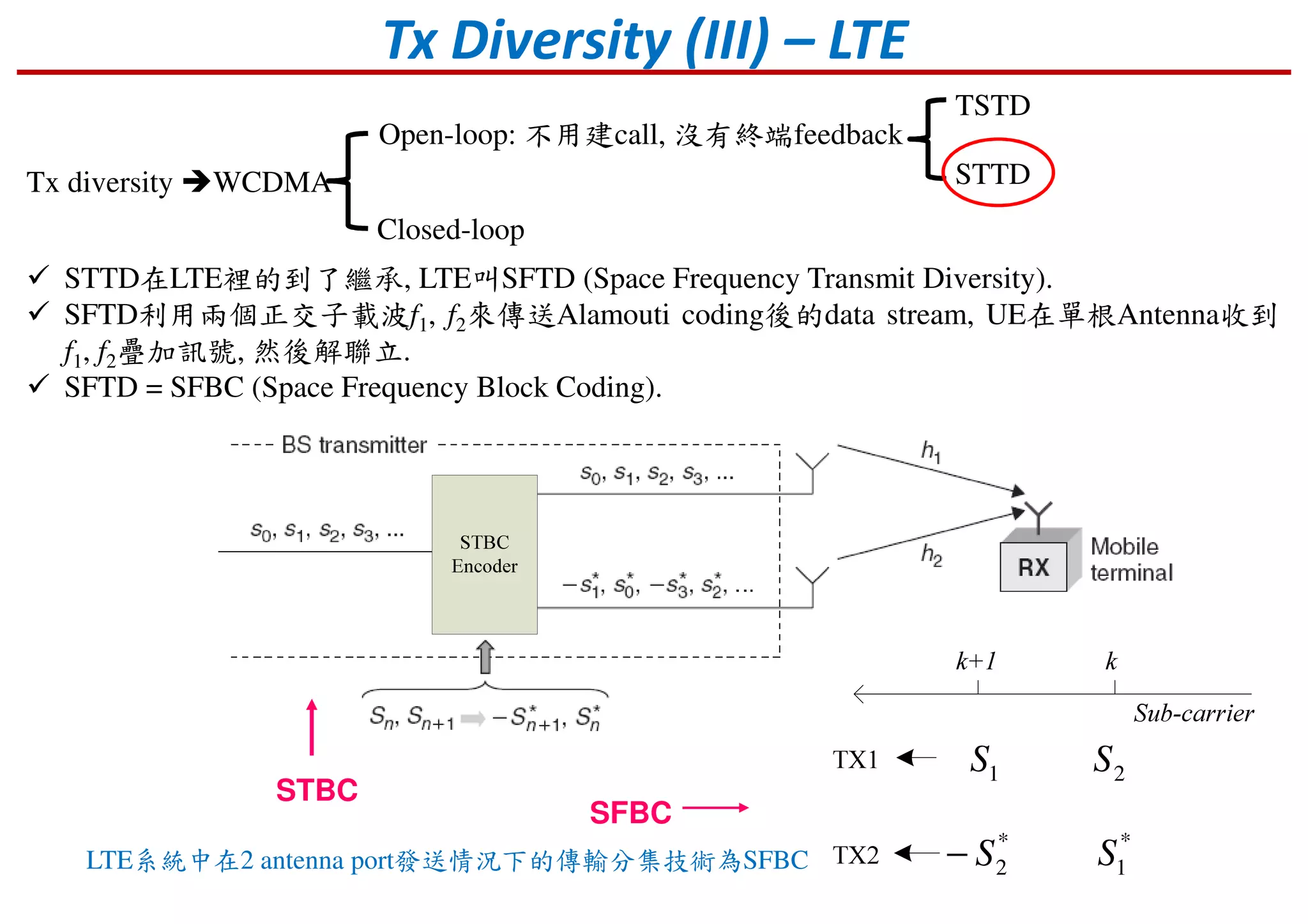
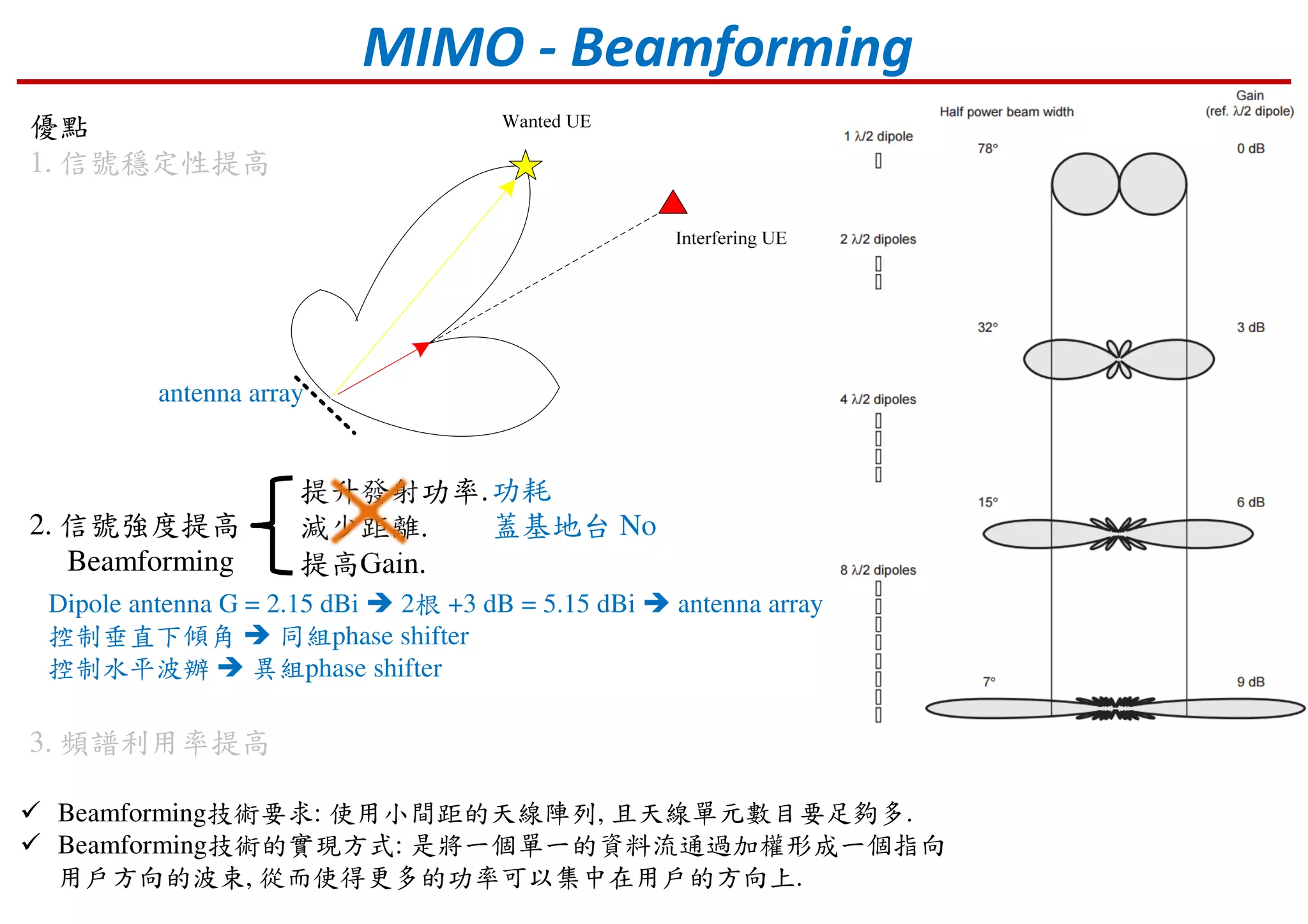
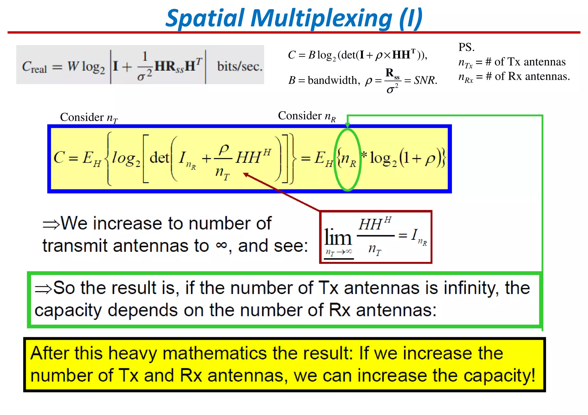
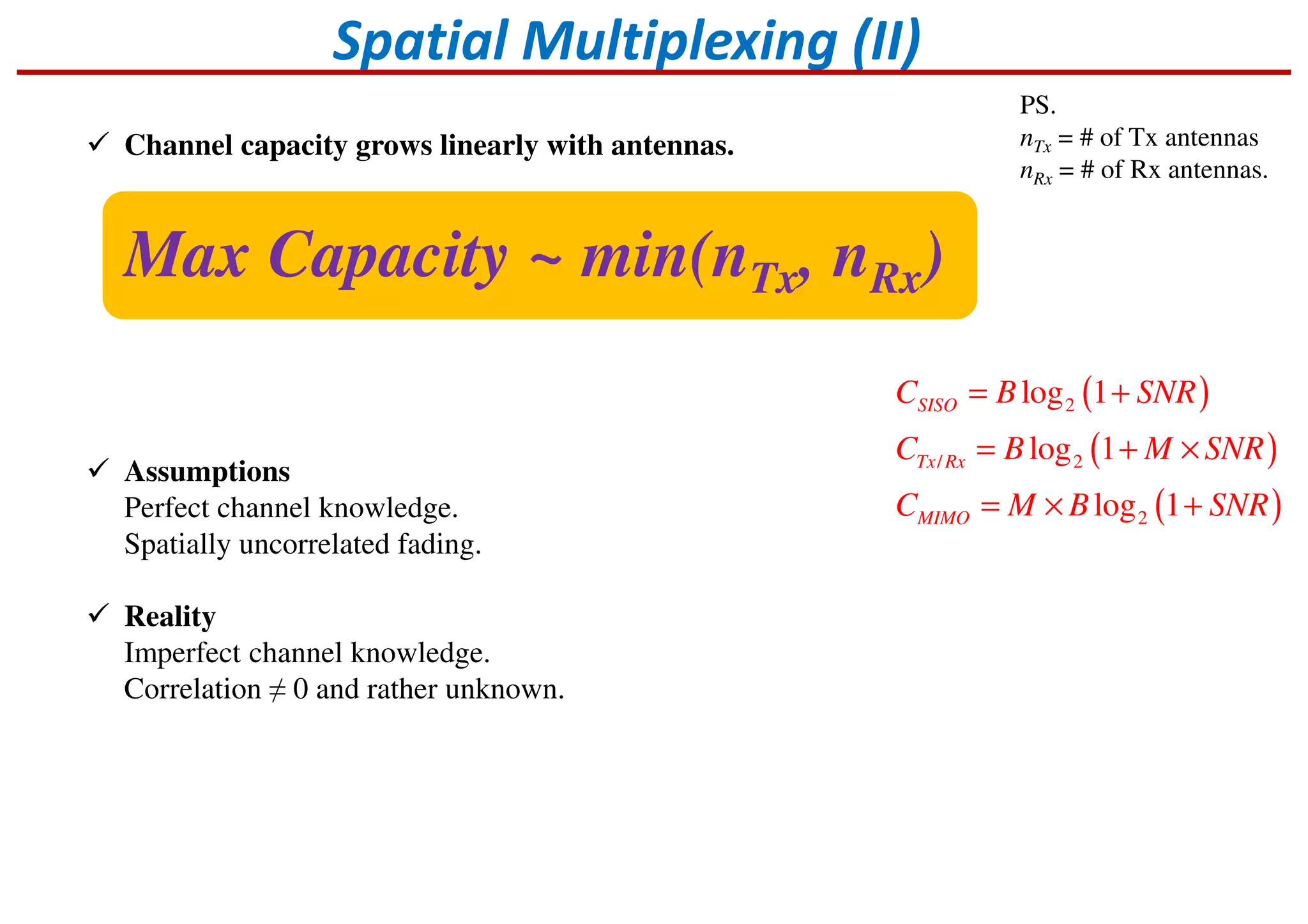
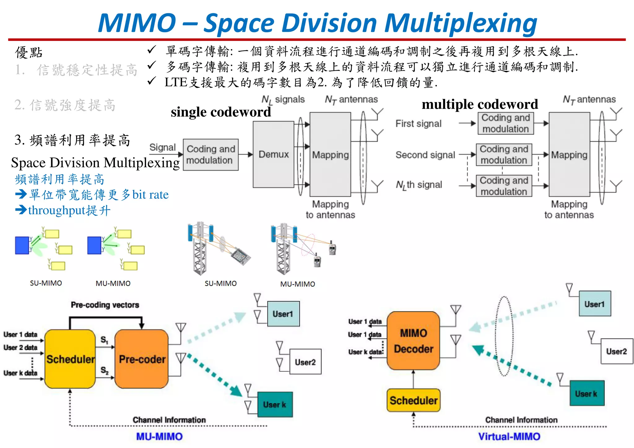
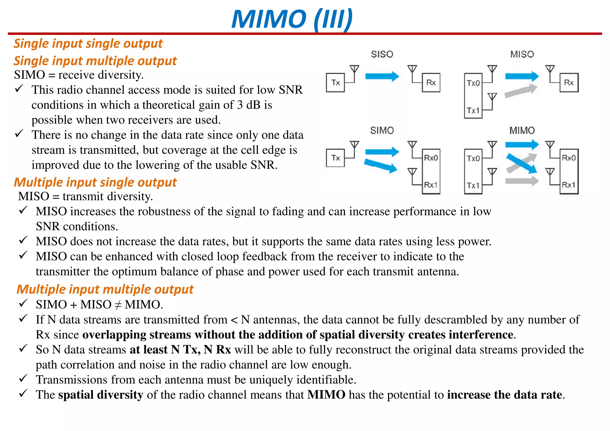
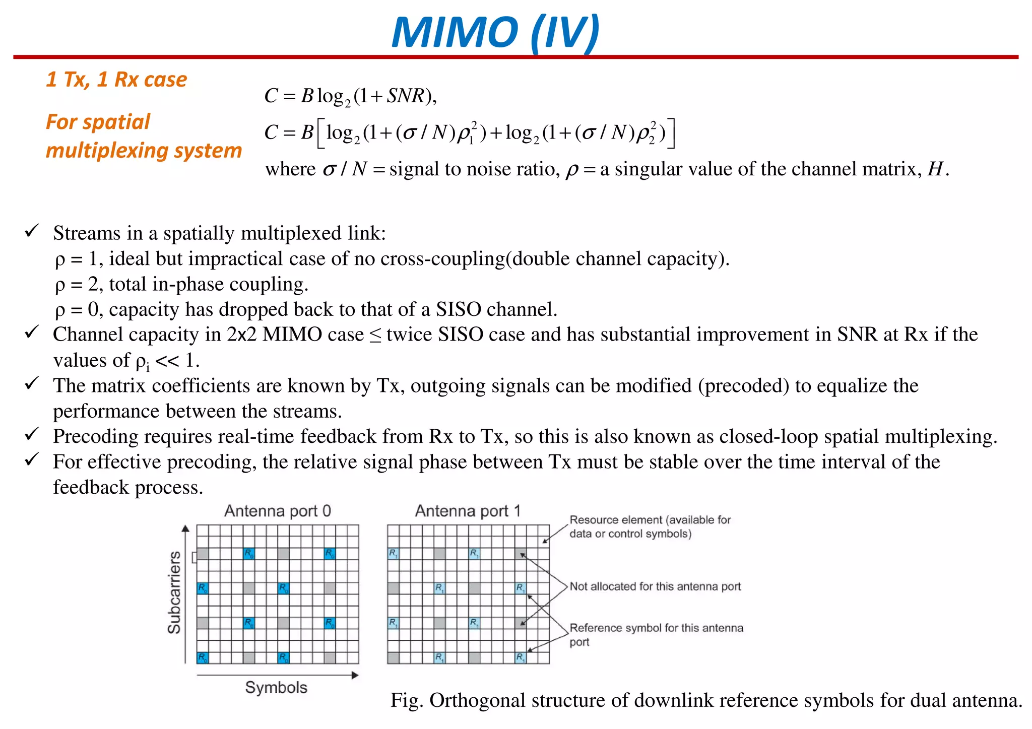
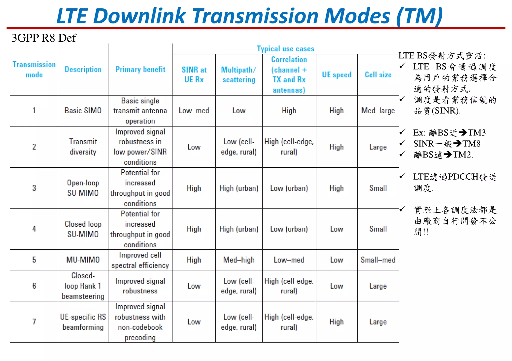
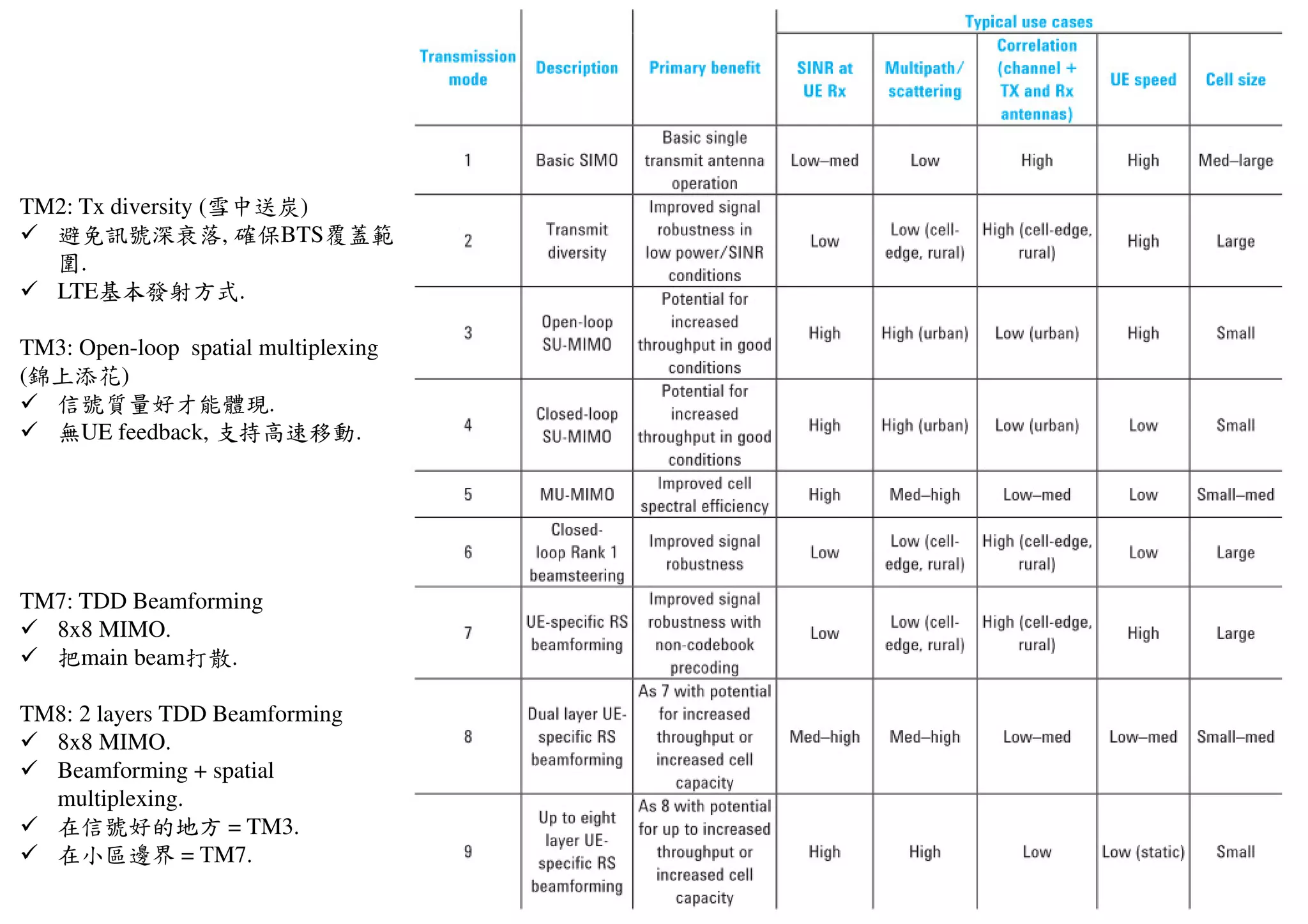
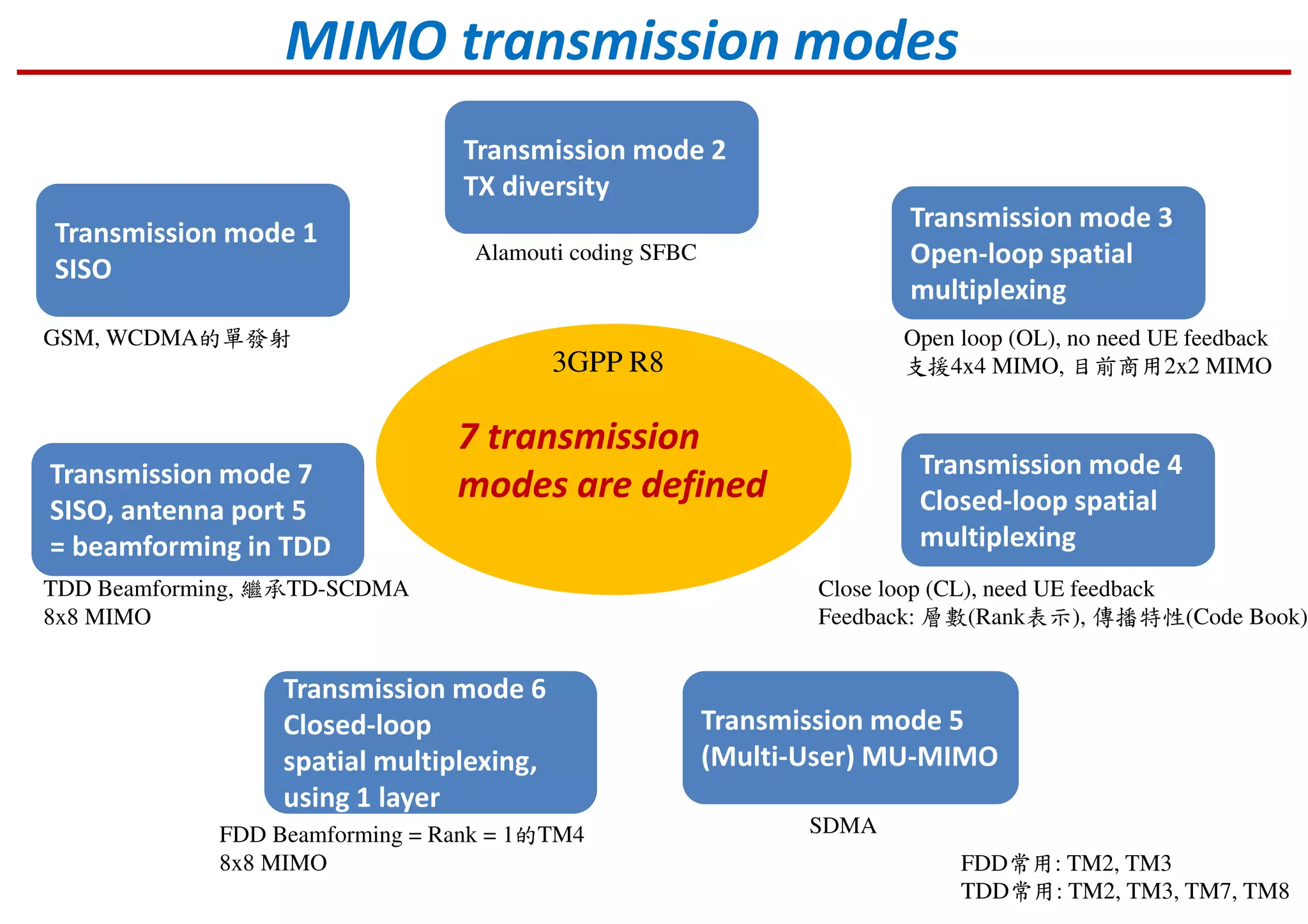
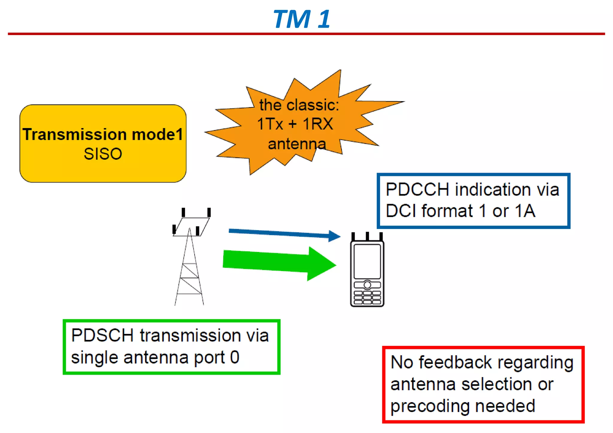
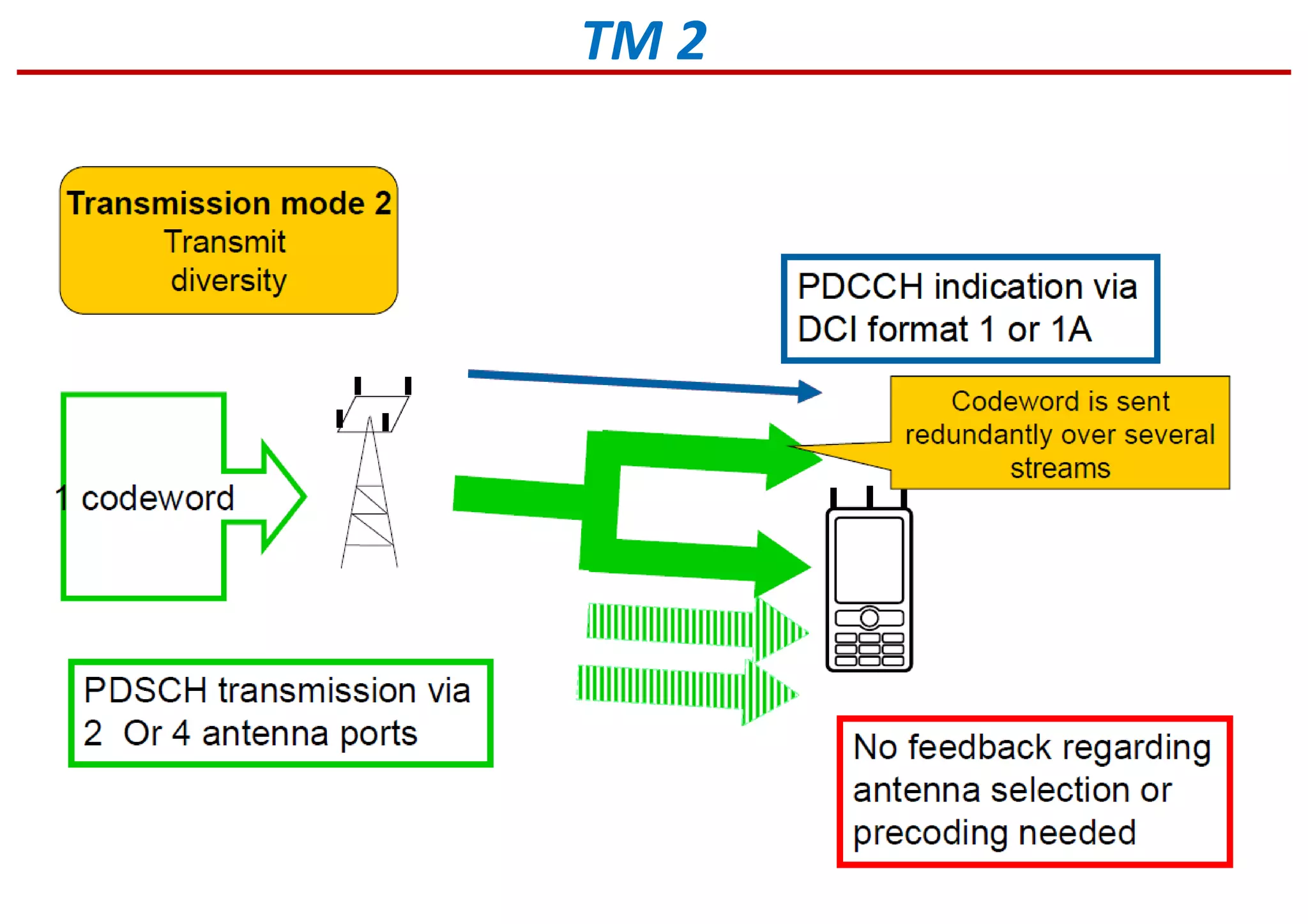
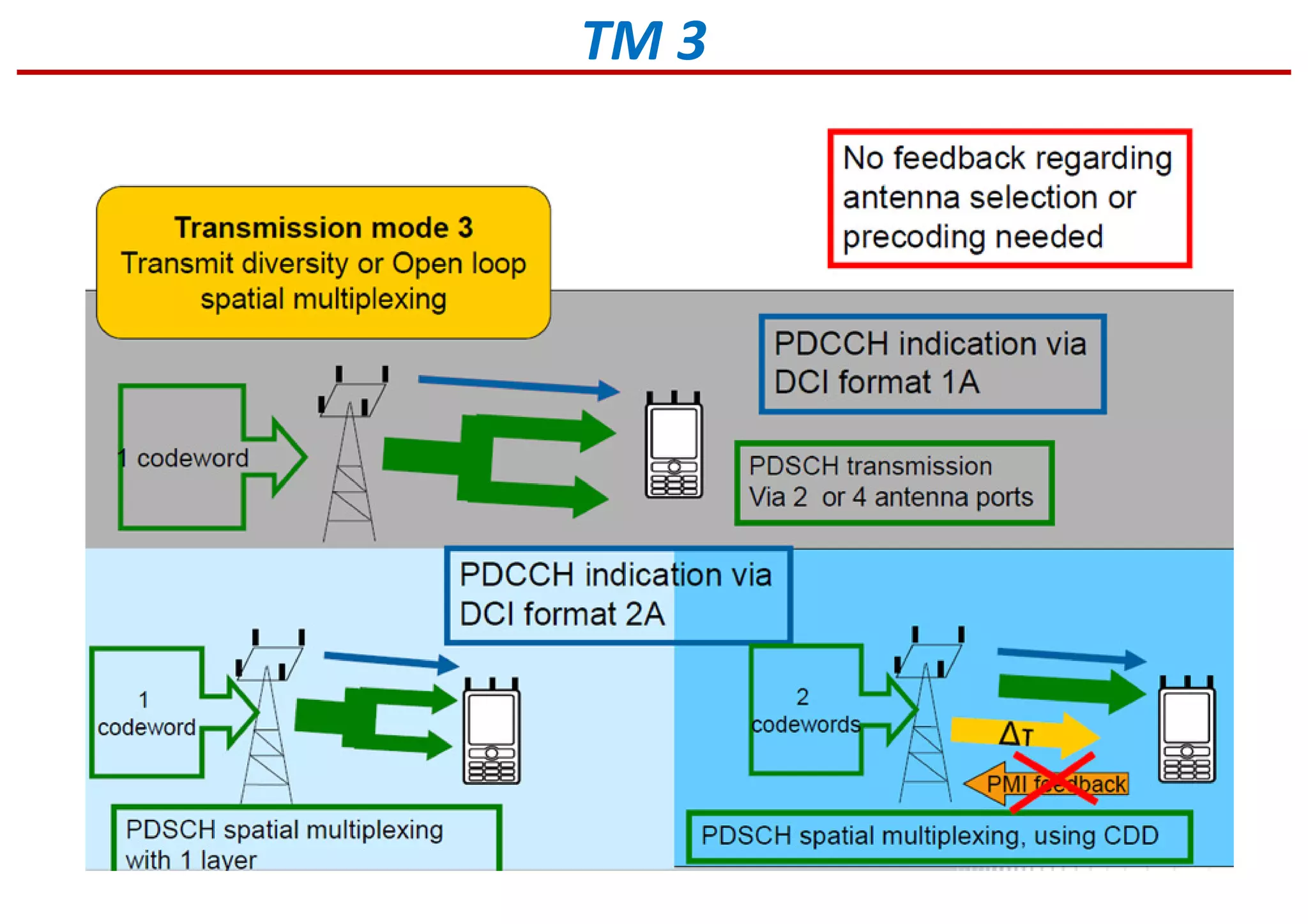
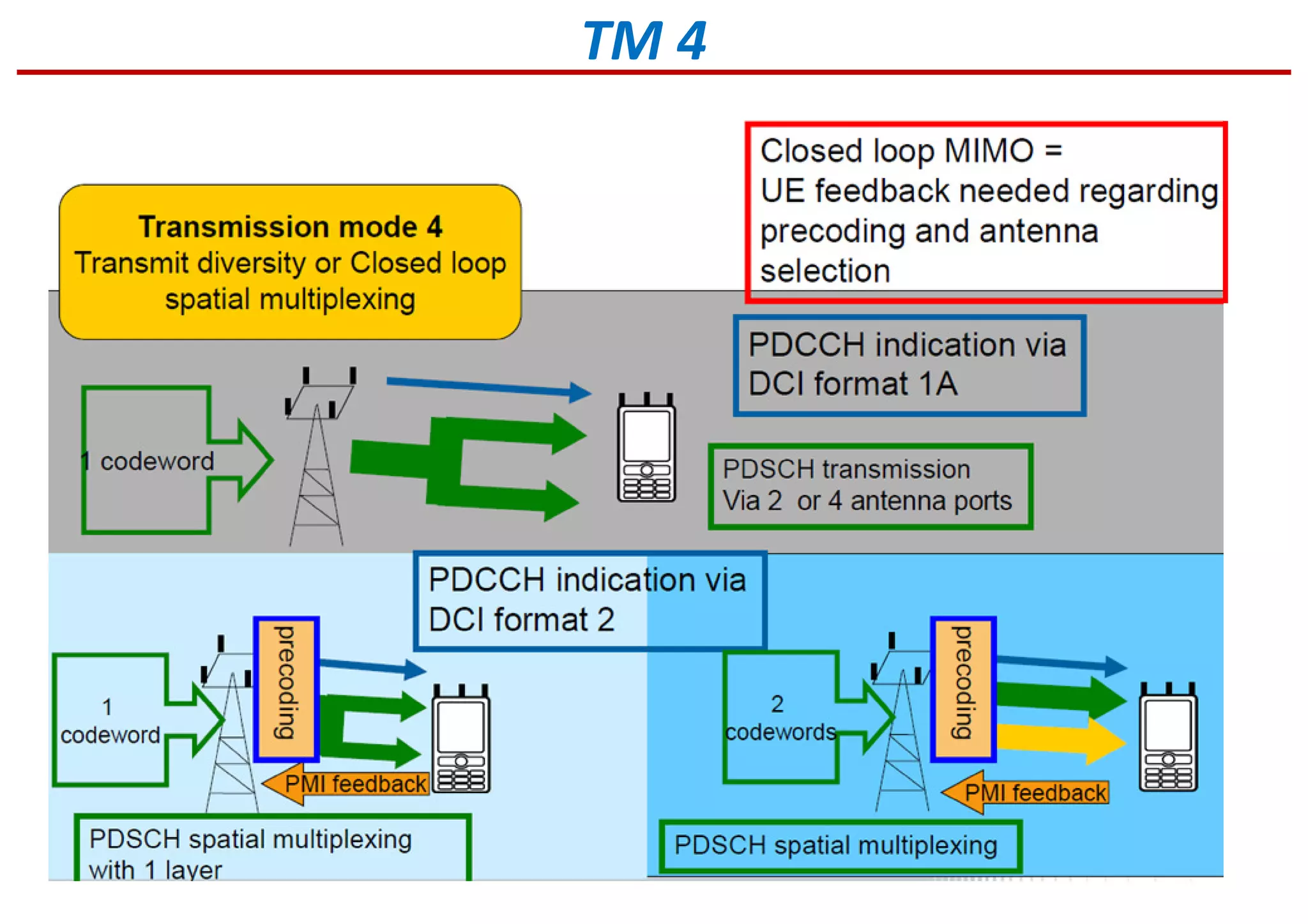
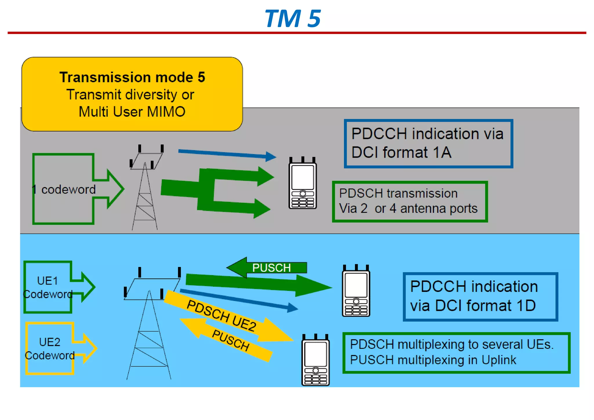
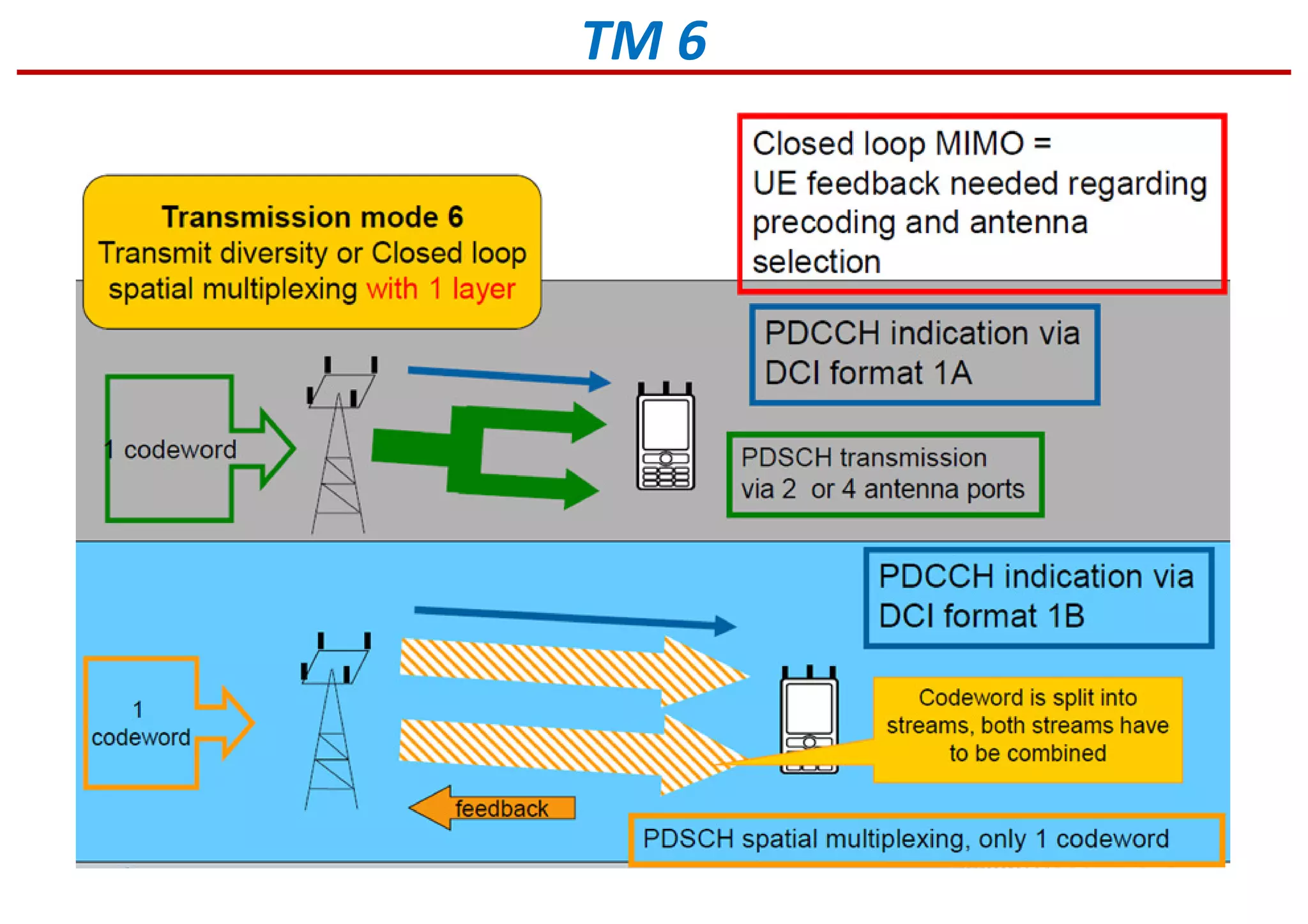
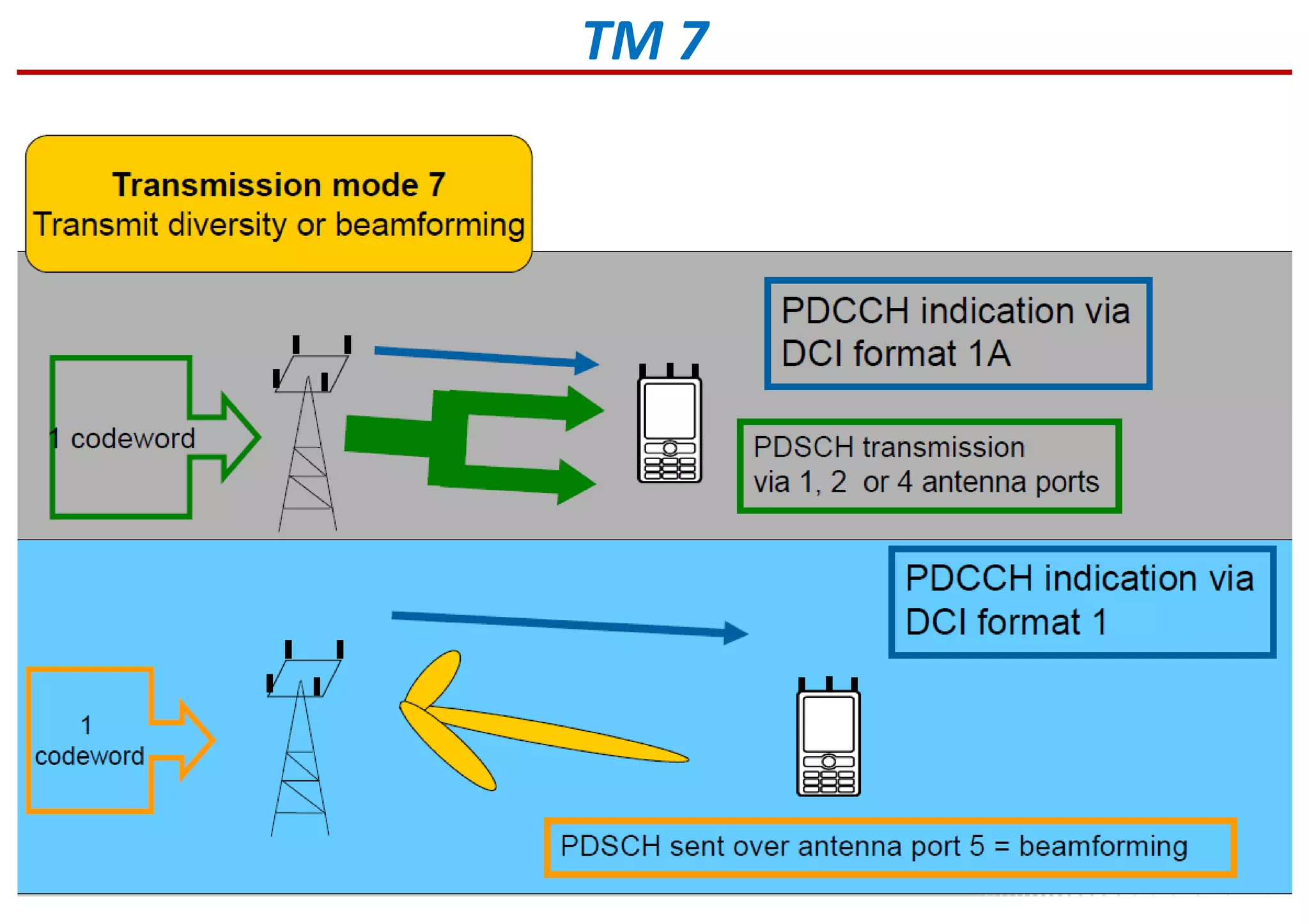
Insights into MIMO technology including aspects of diversity, beamforming, and spatial multiplexing.
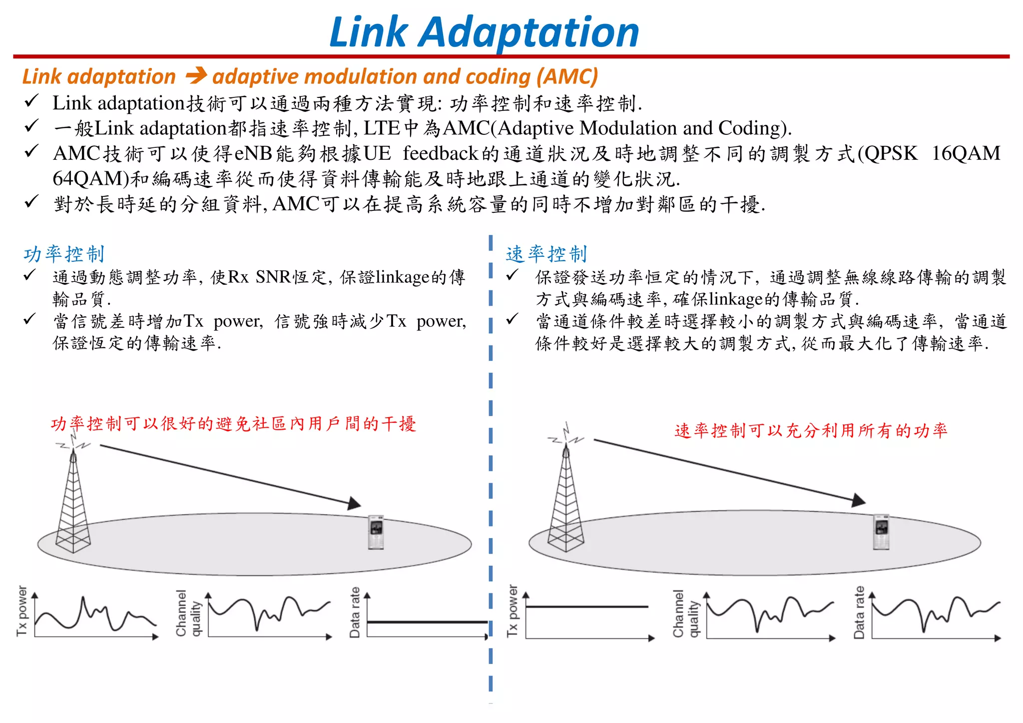
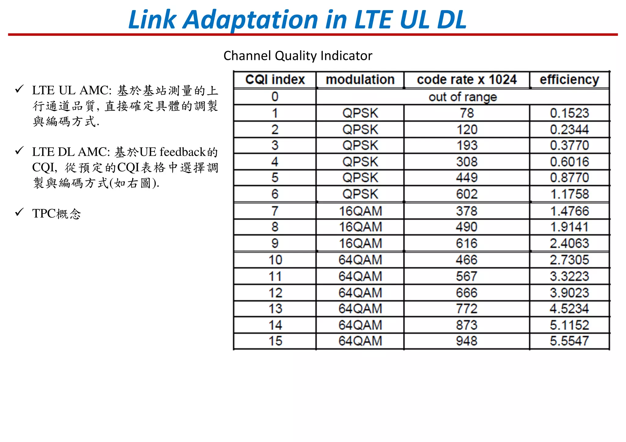
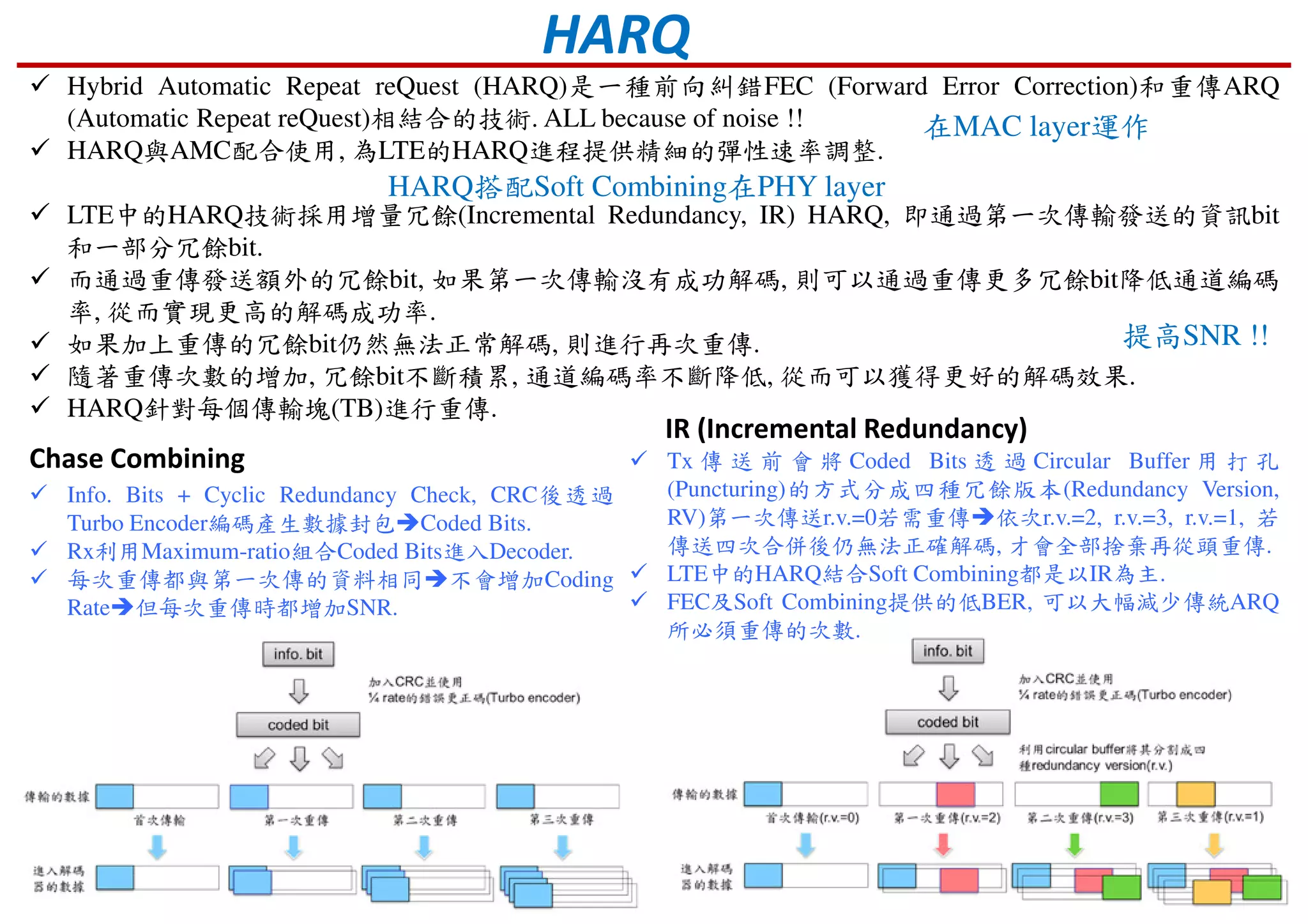
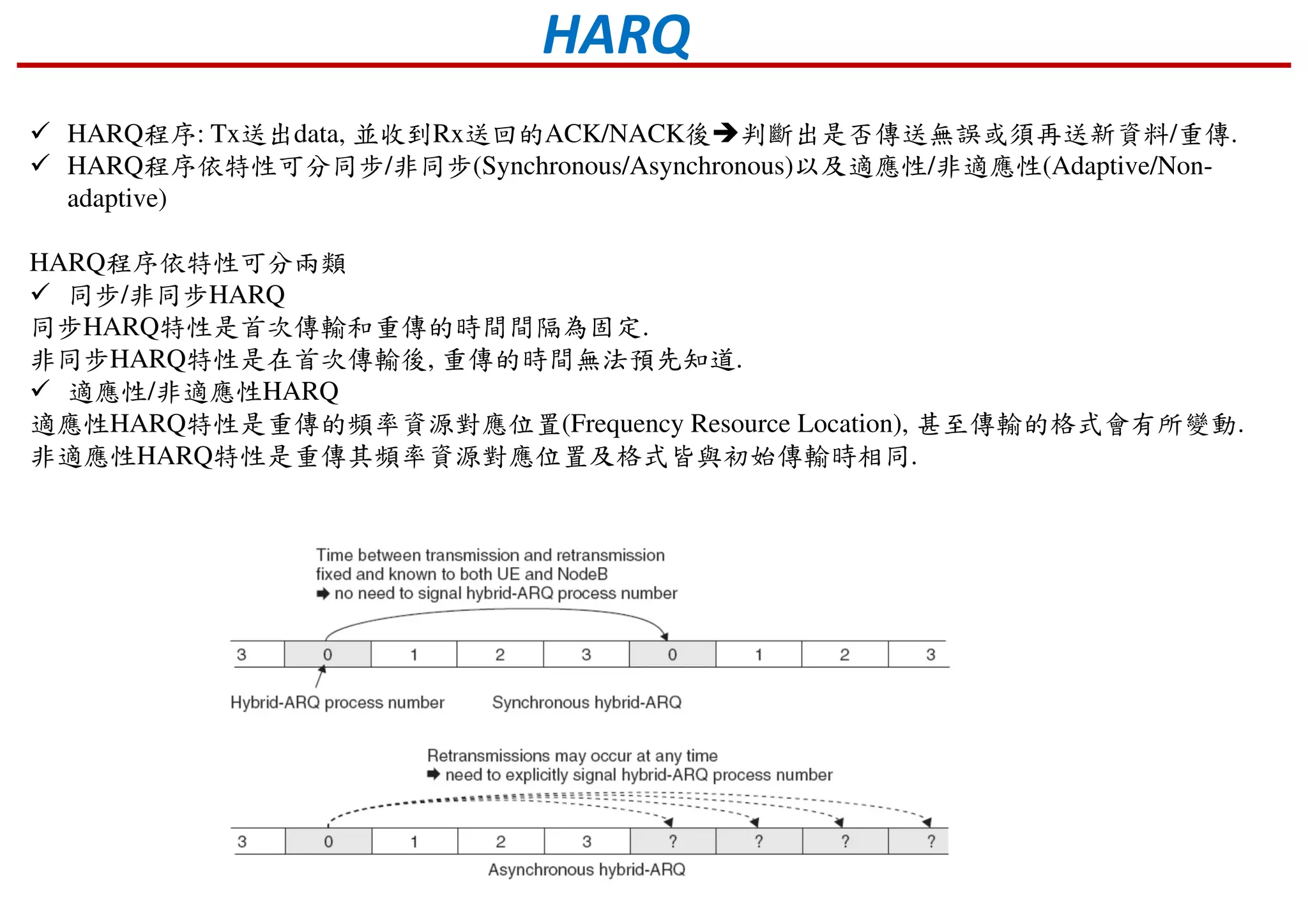
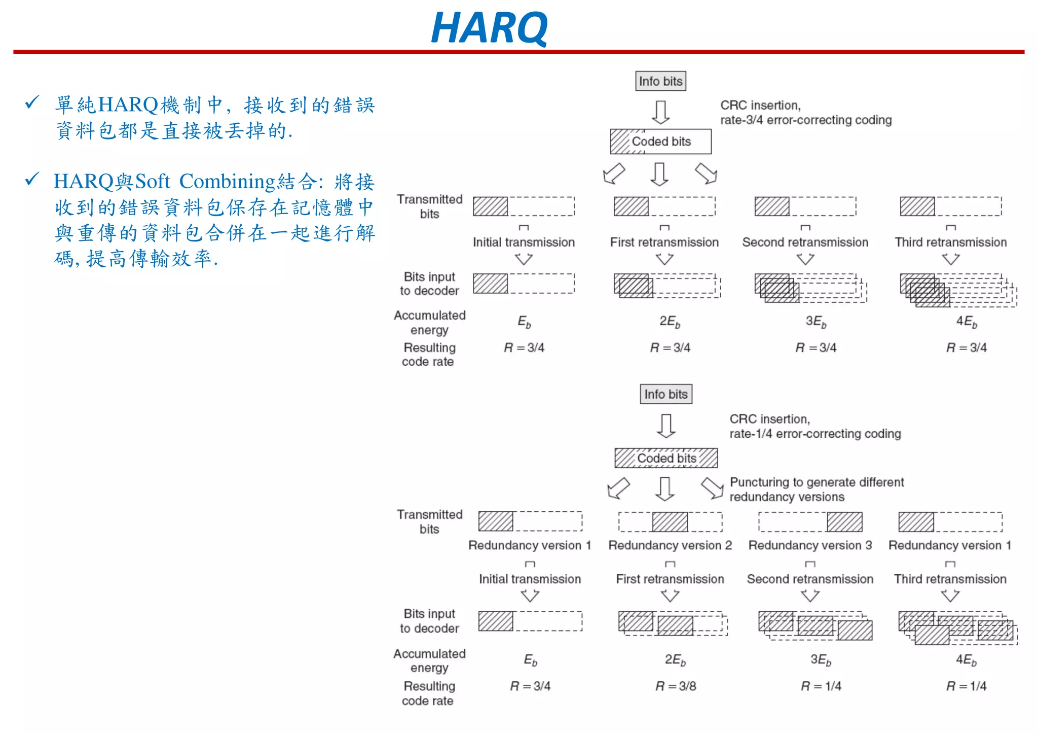
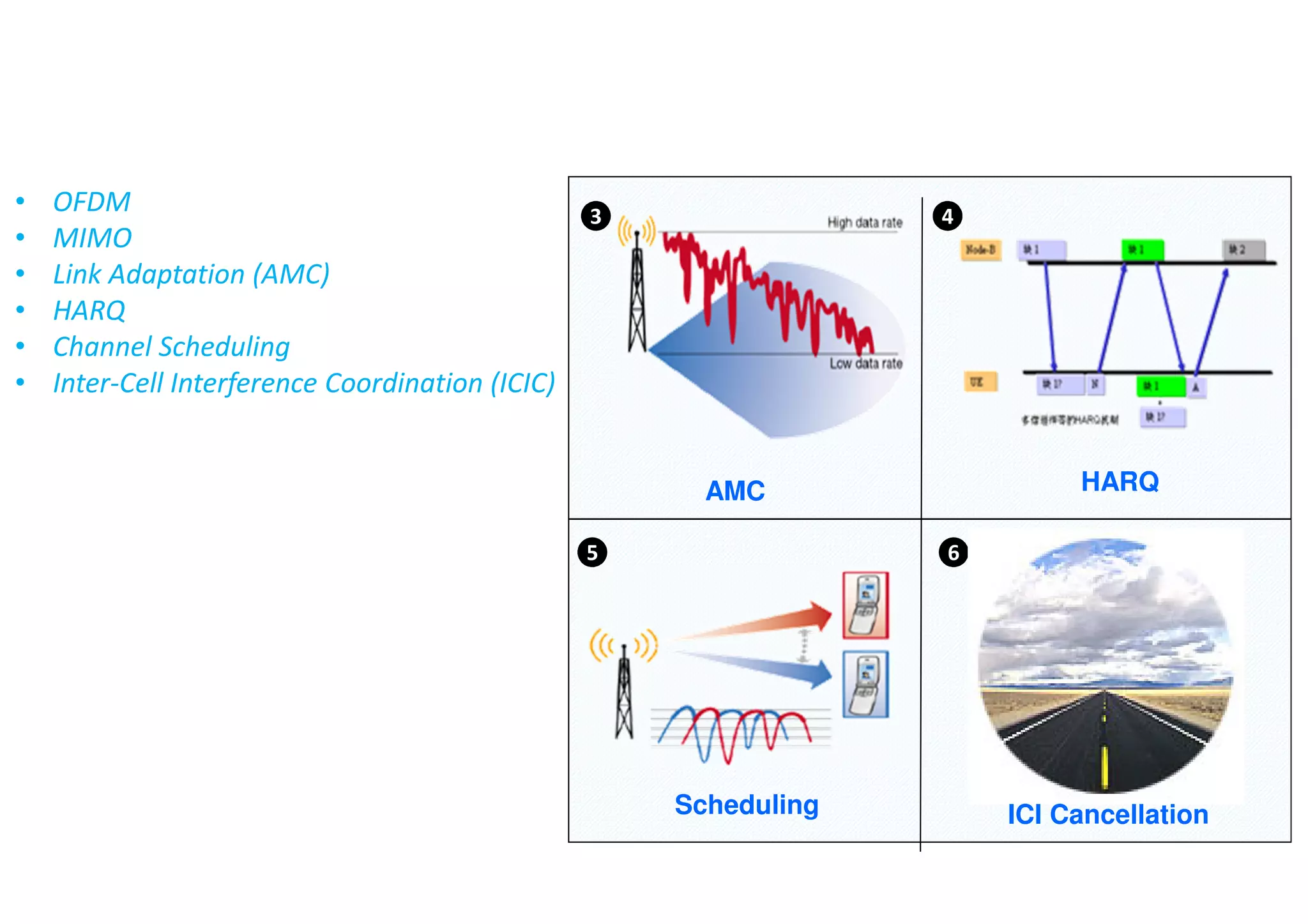
Explanation of link adaptation techniques, specifically AMC and how HARQ operates.
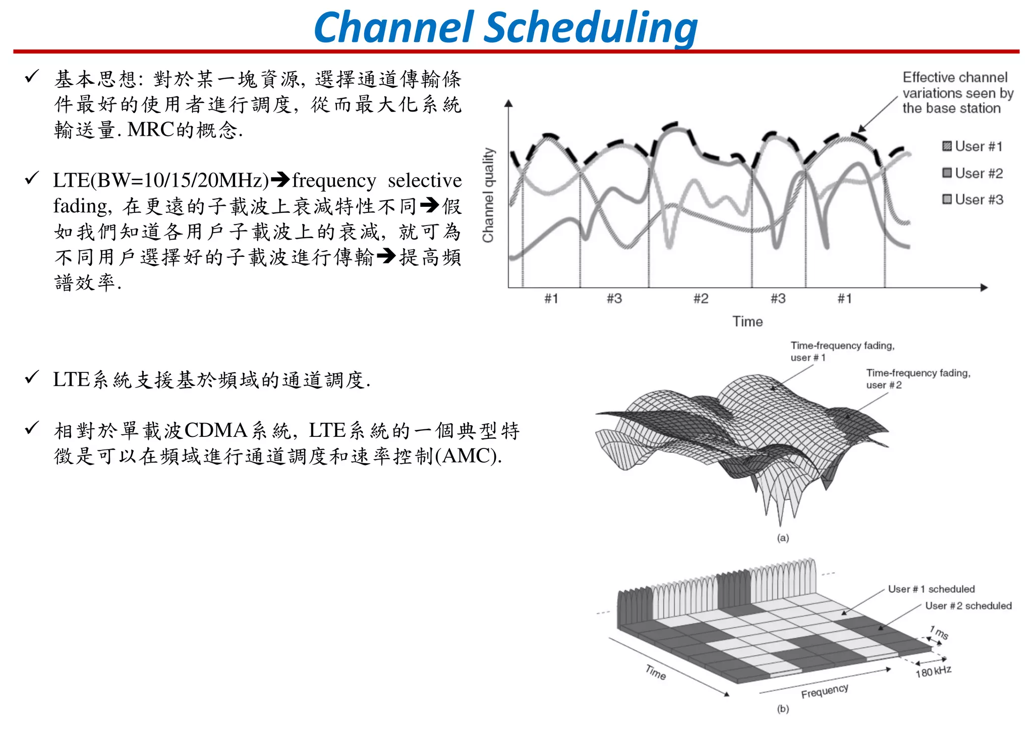
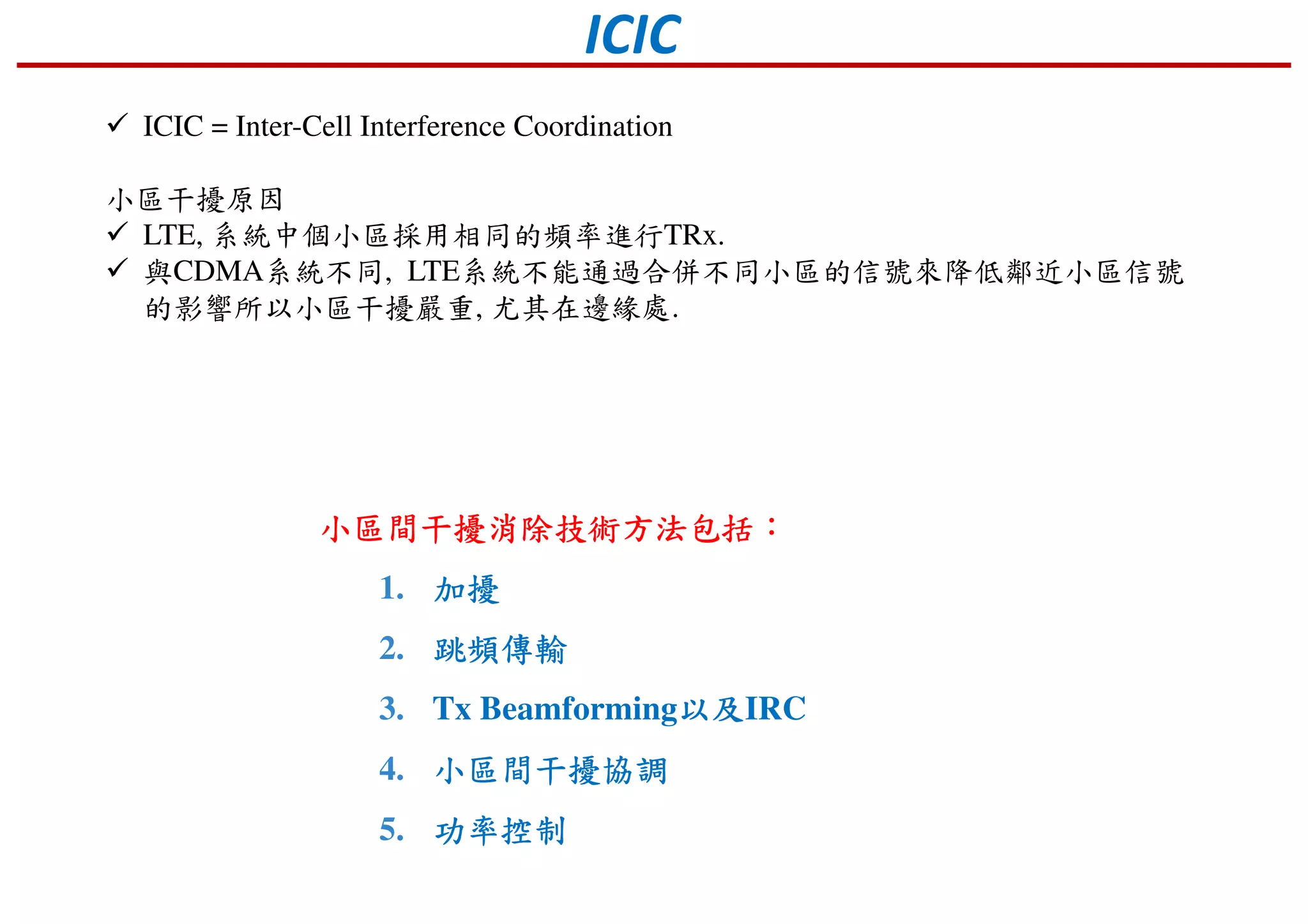
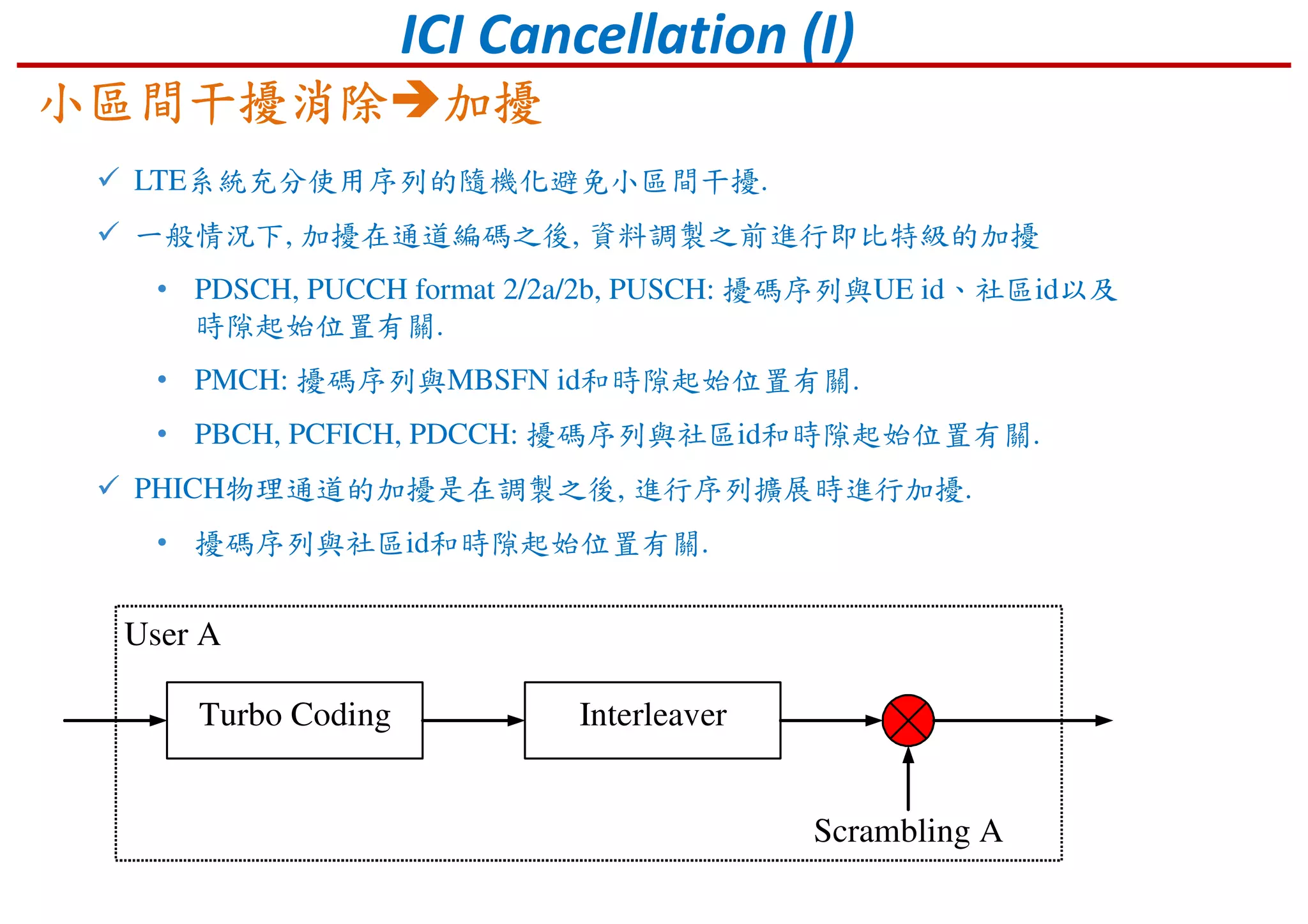
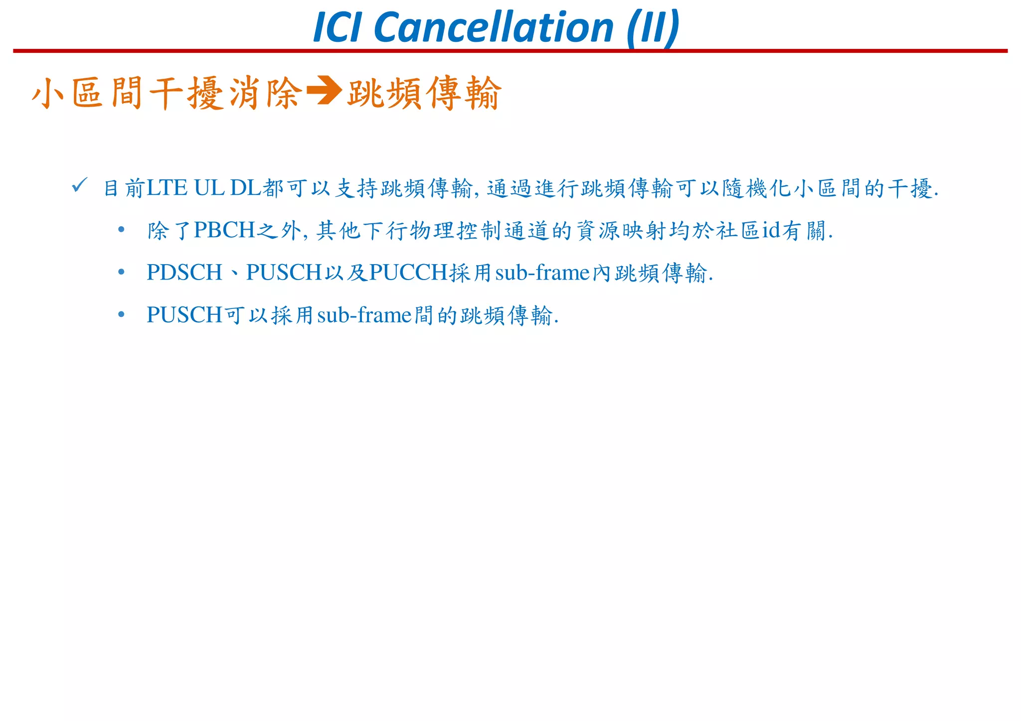
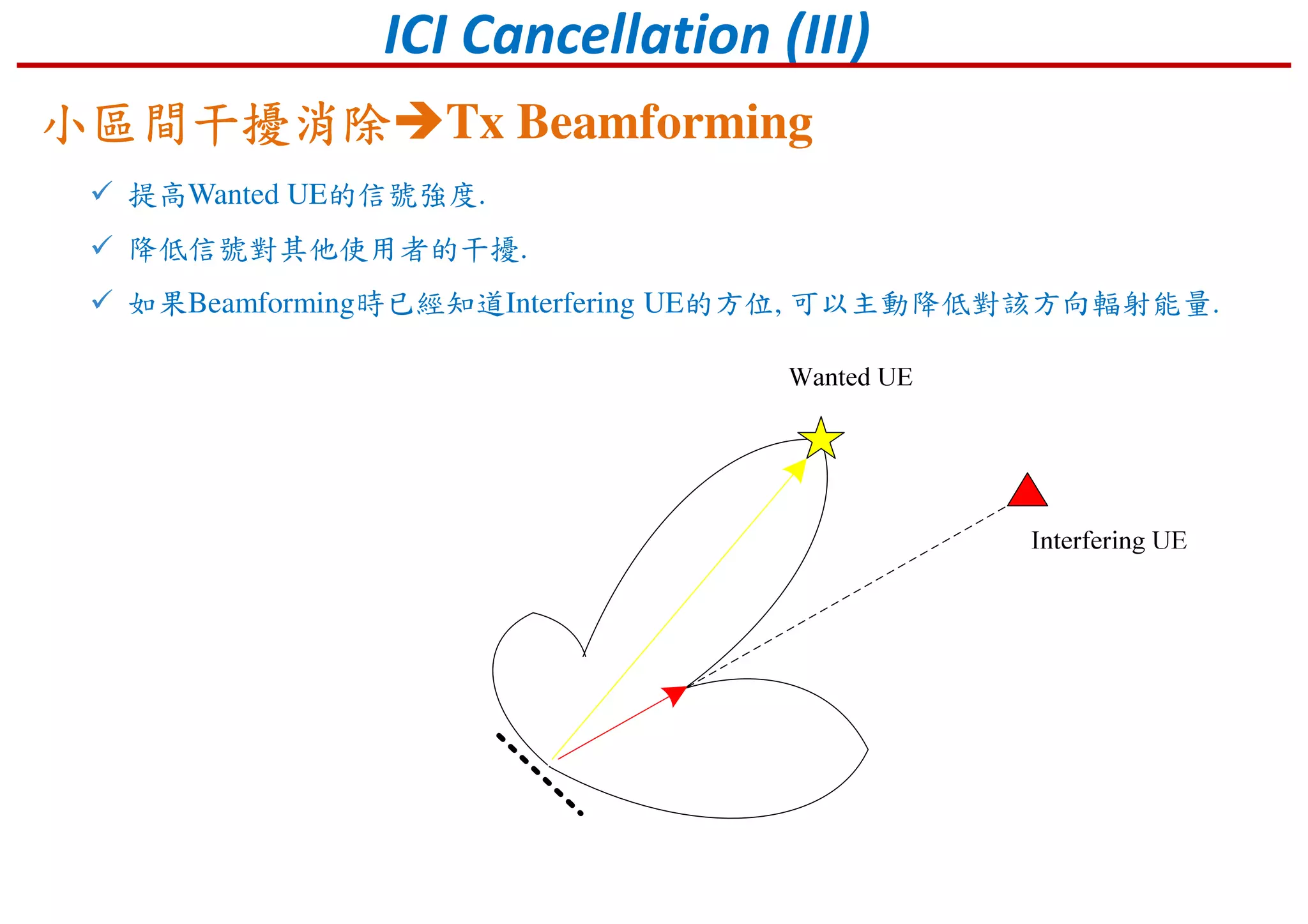
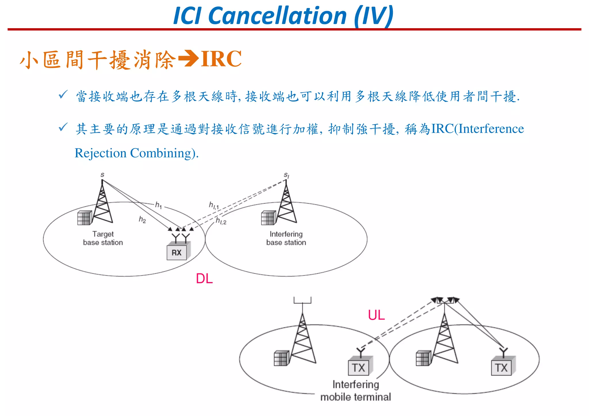
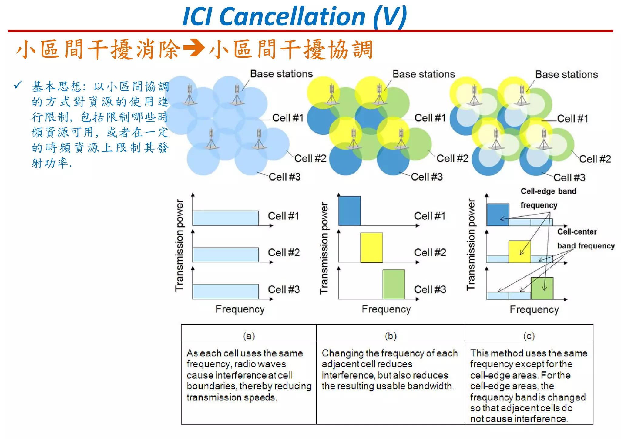
Introduction to LTE channel scheduling approaches and methods to mitigate inter-cell interference.
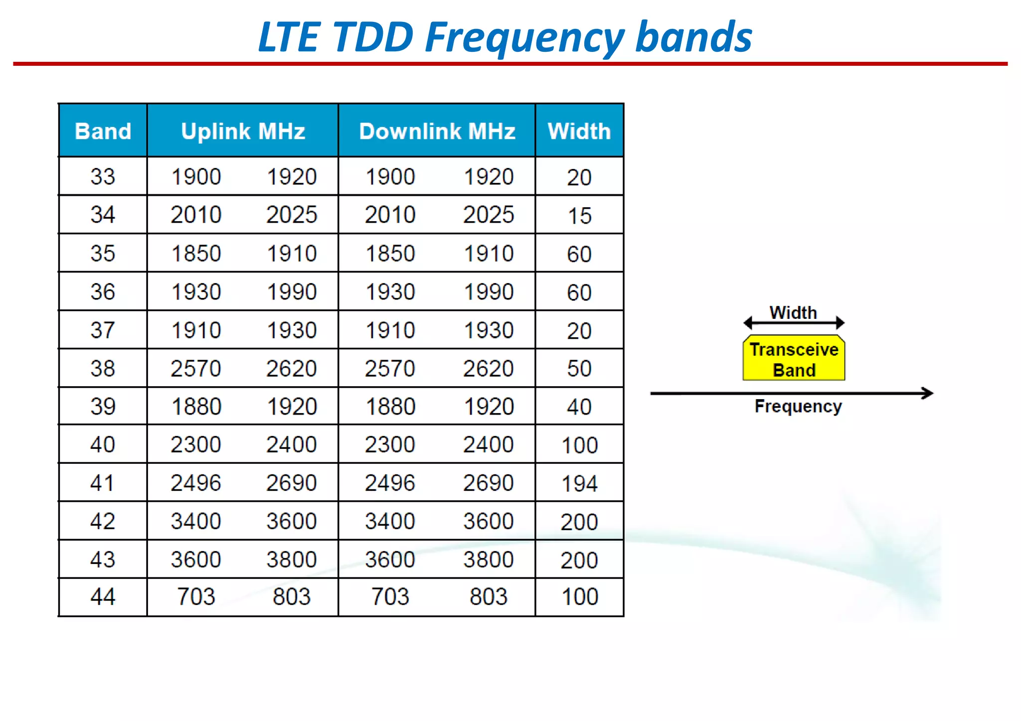
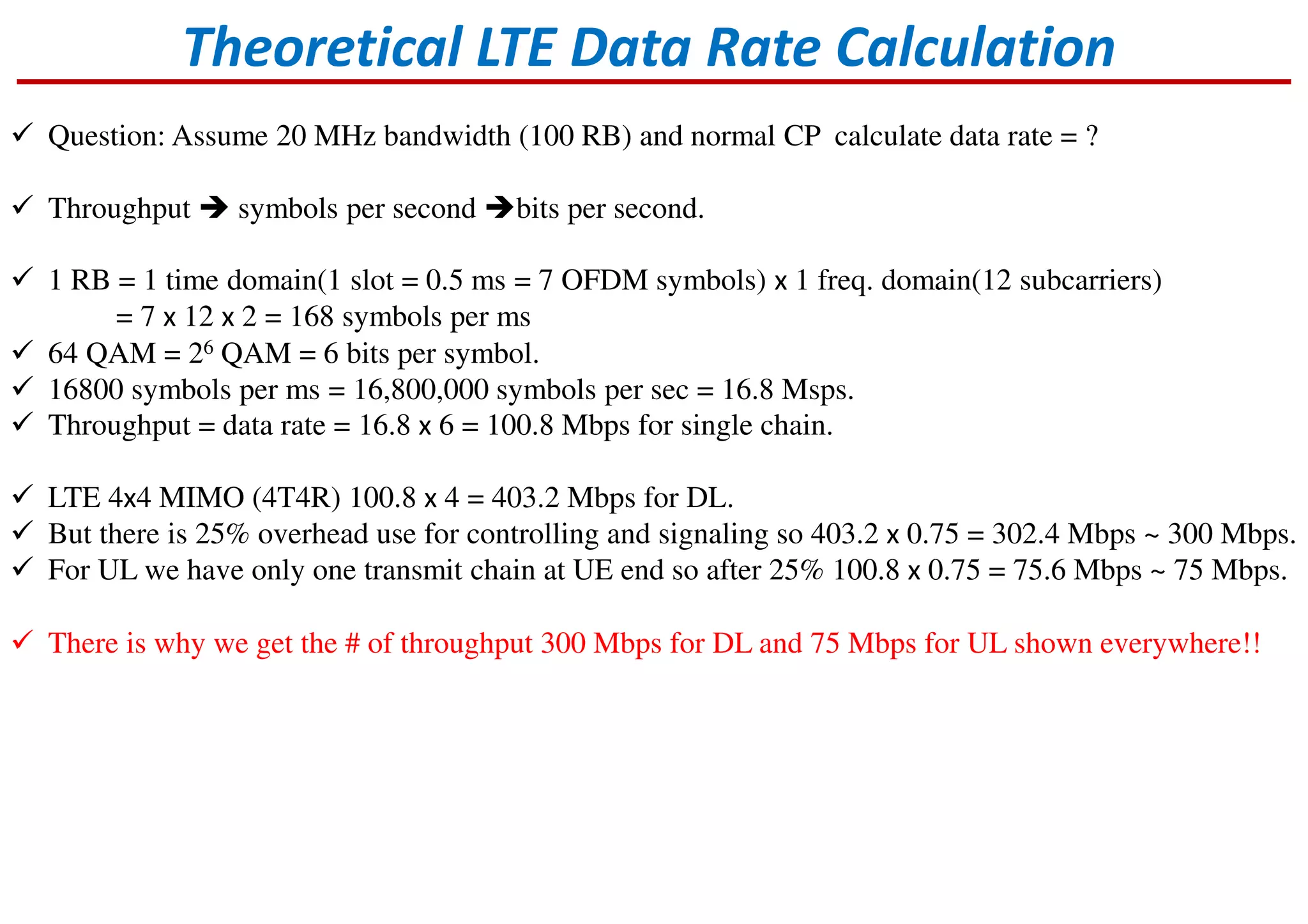
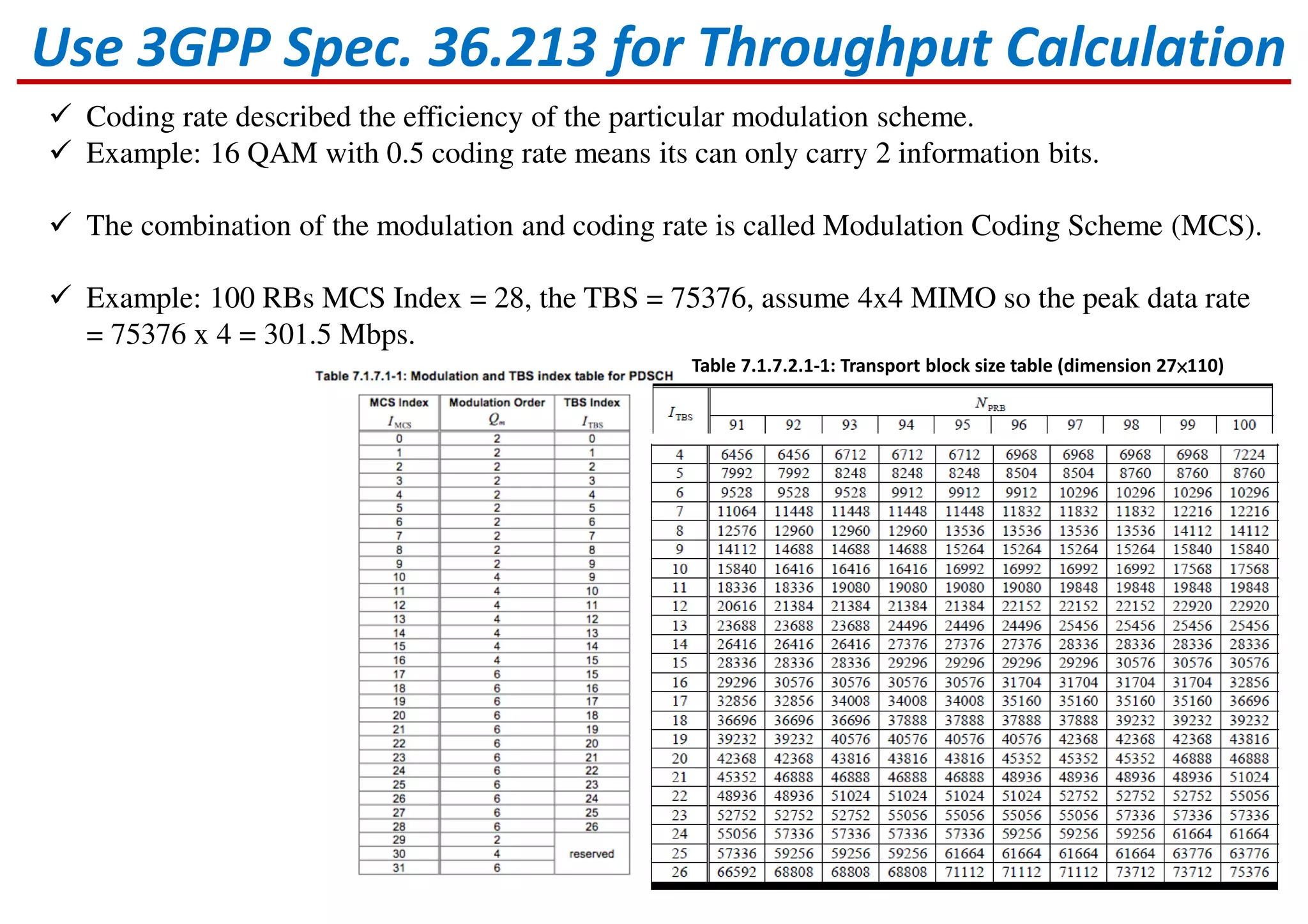
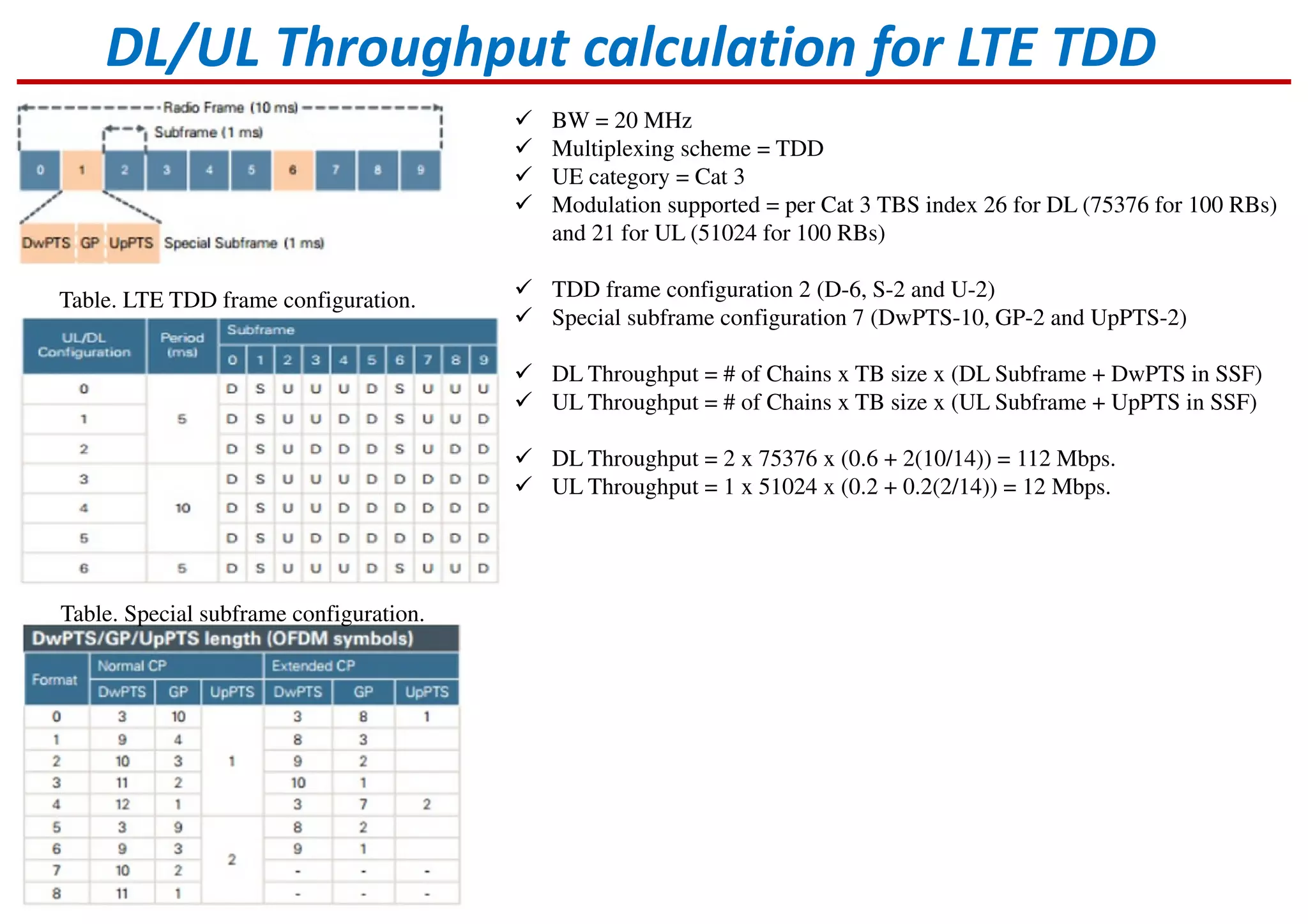
Details on LTE frequency bands and calculations for data rates based on various parameters.
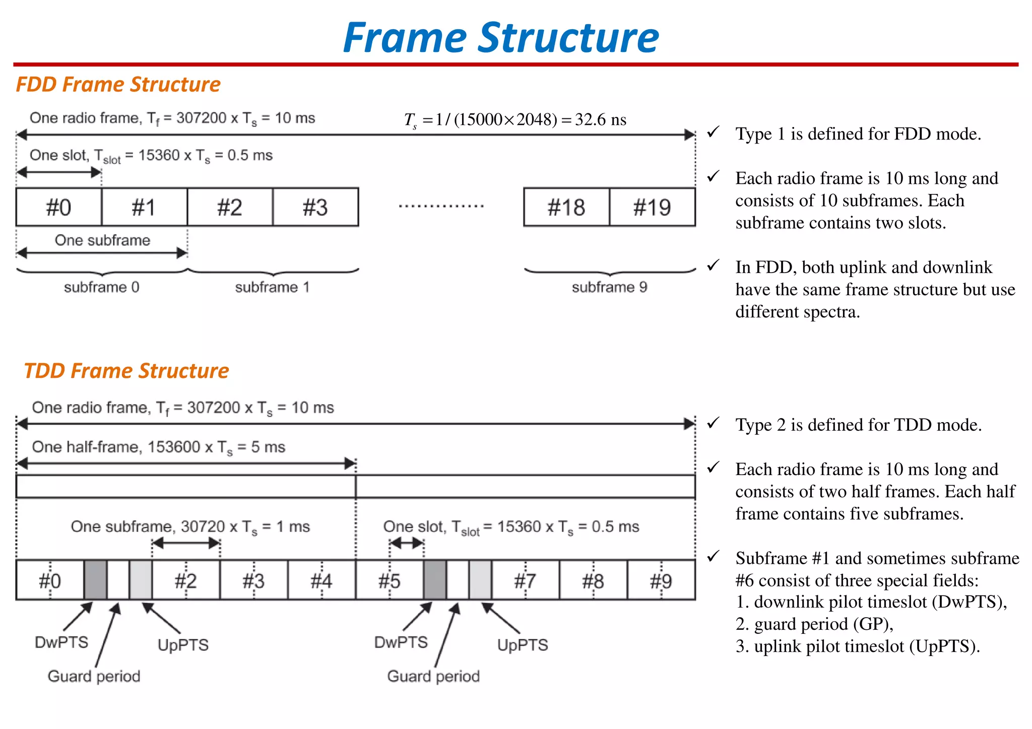
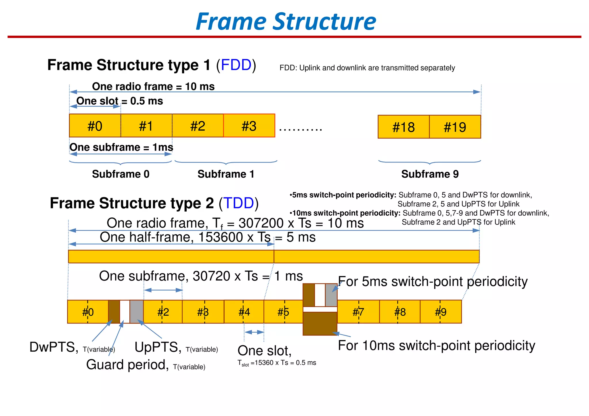
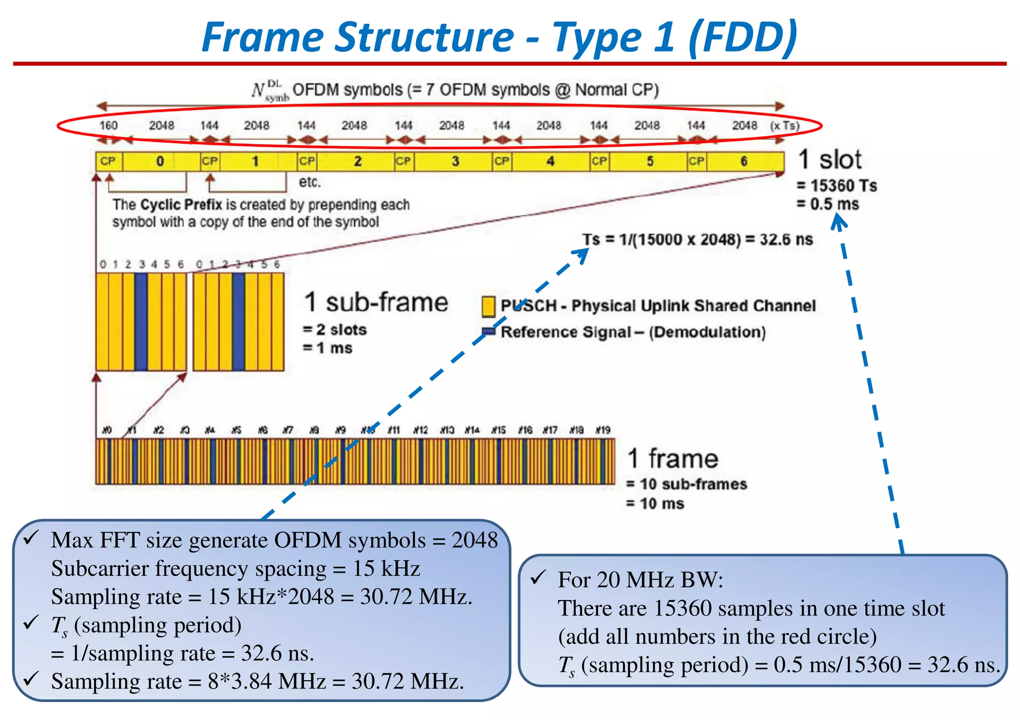
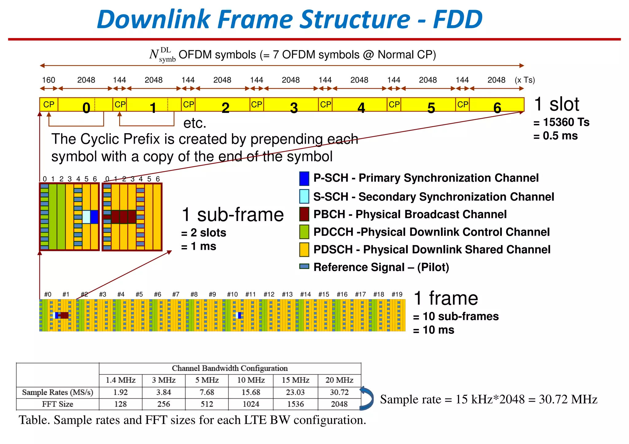
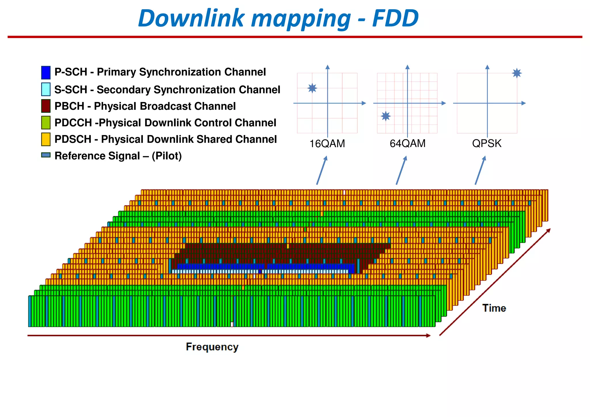
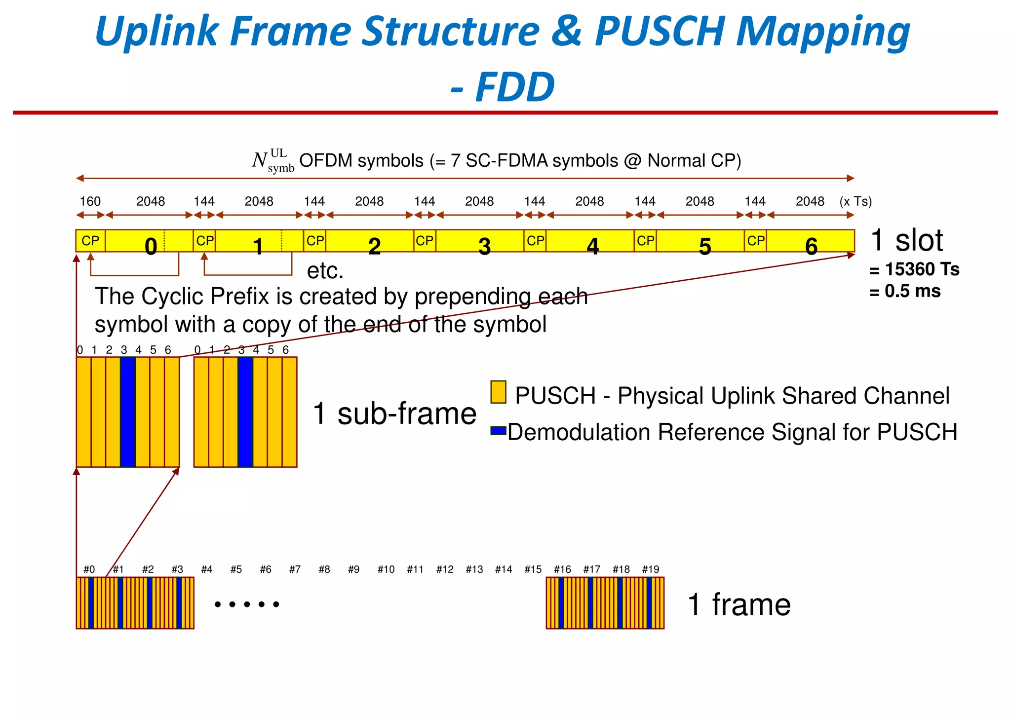
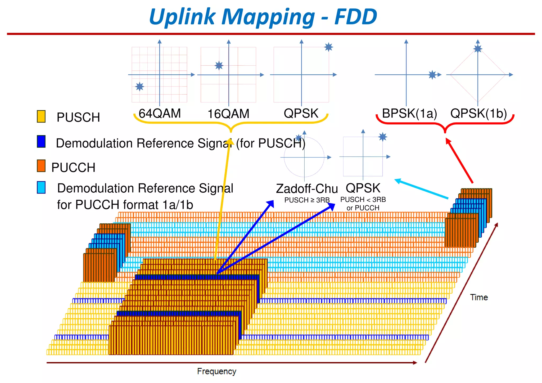
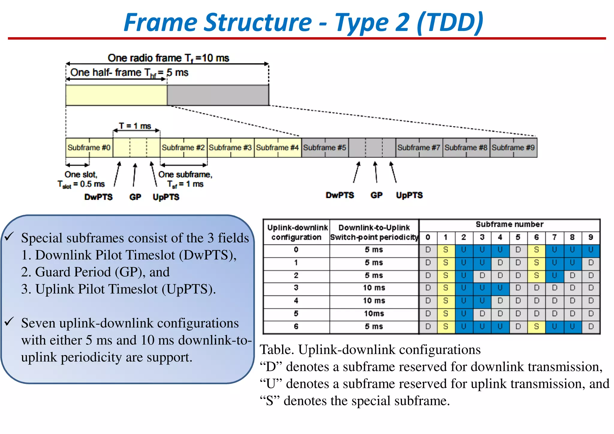
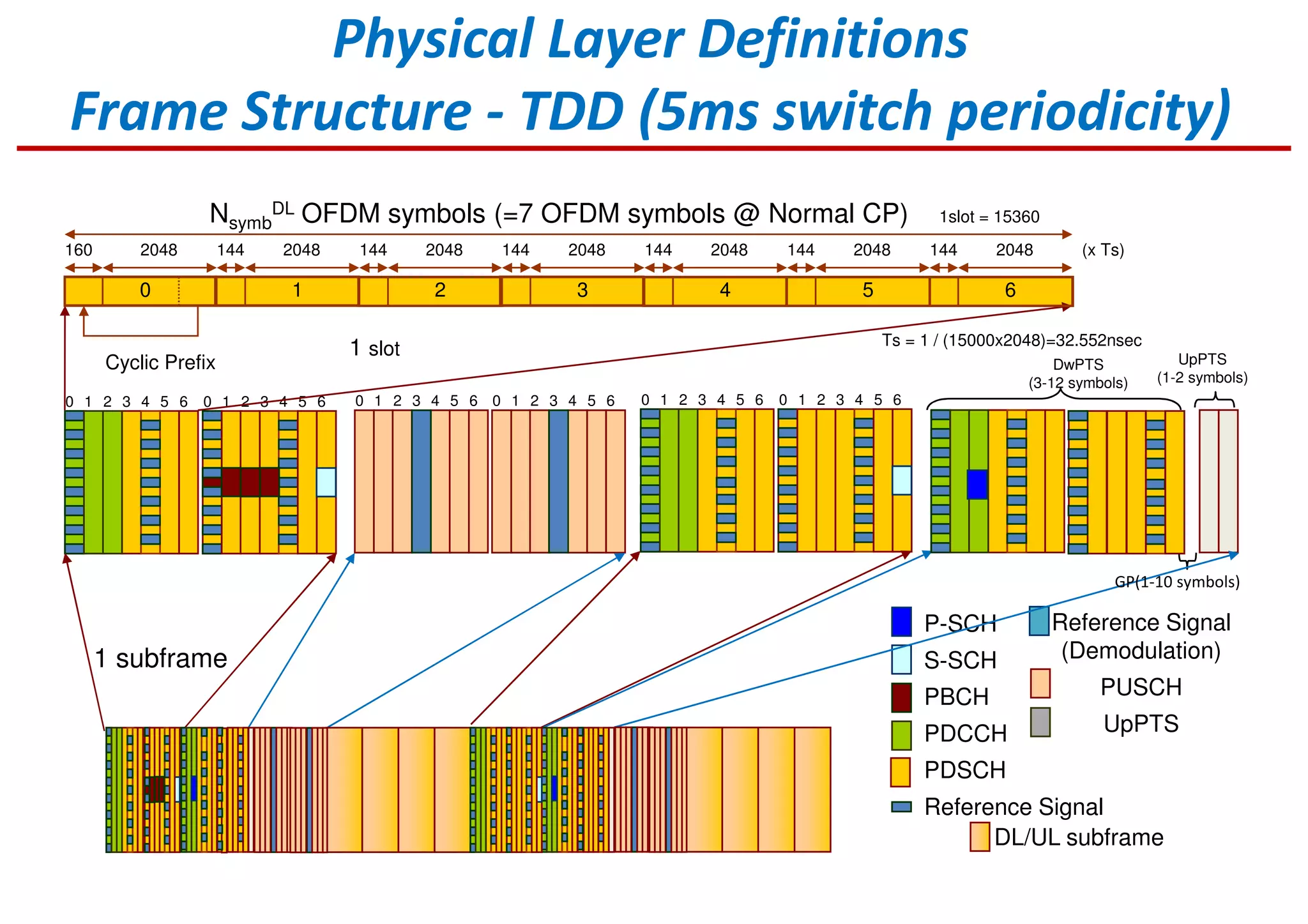
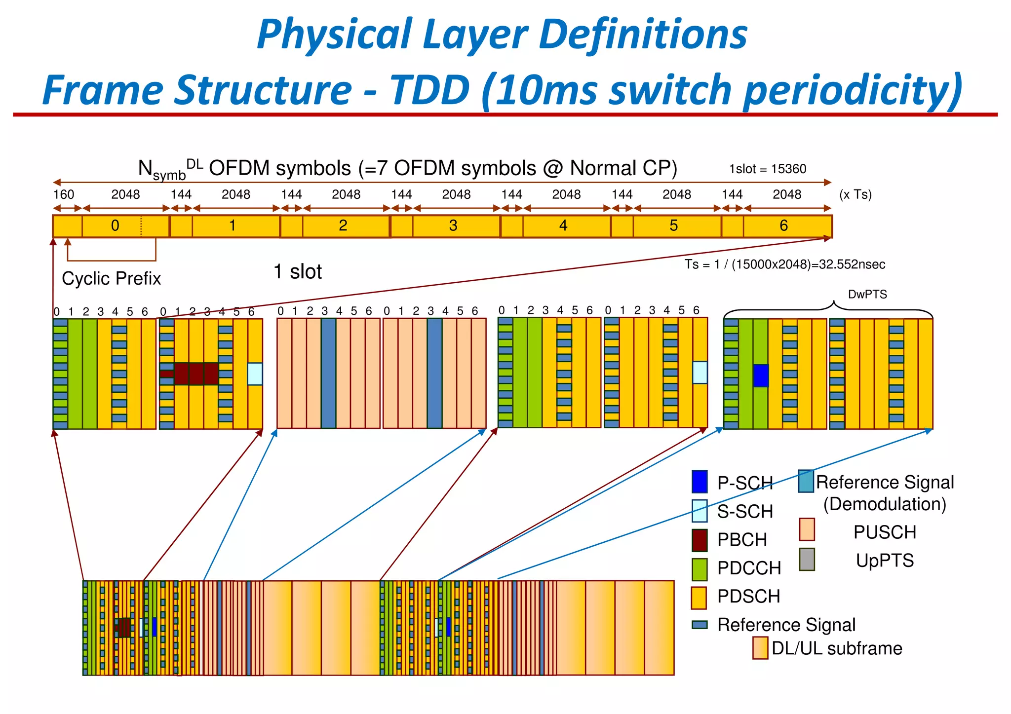
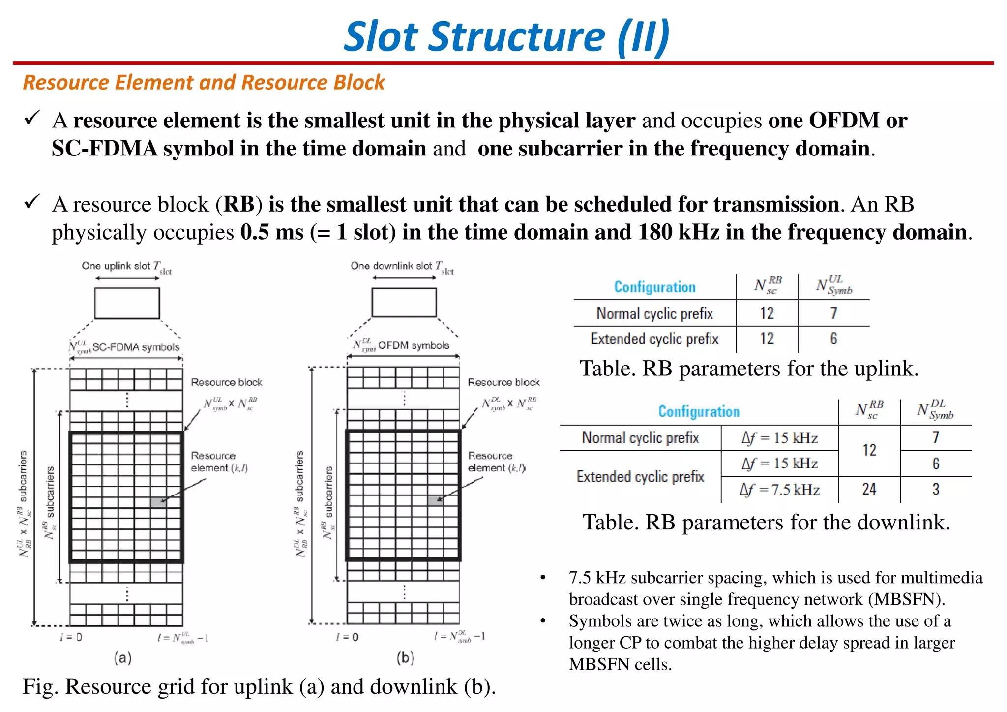
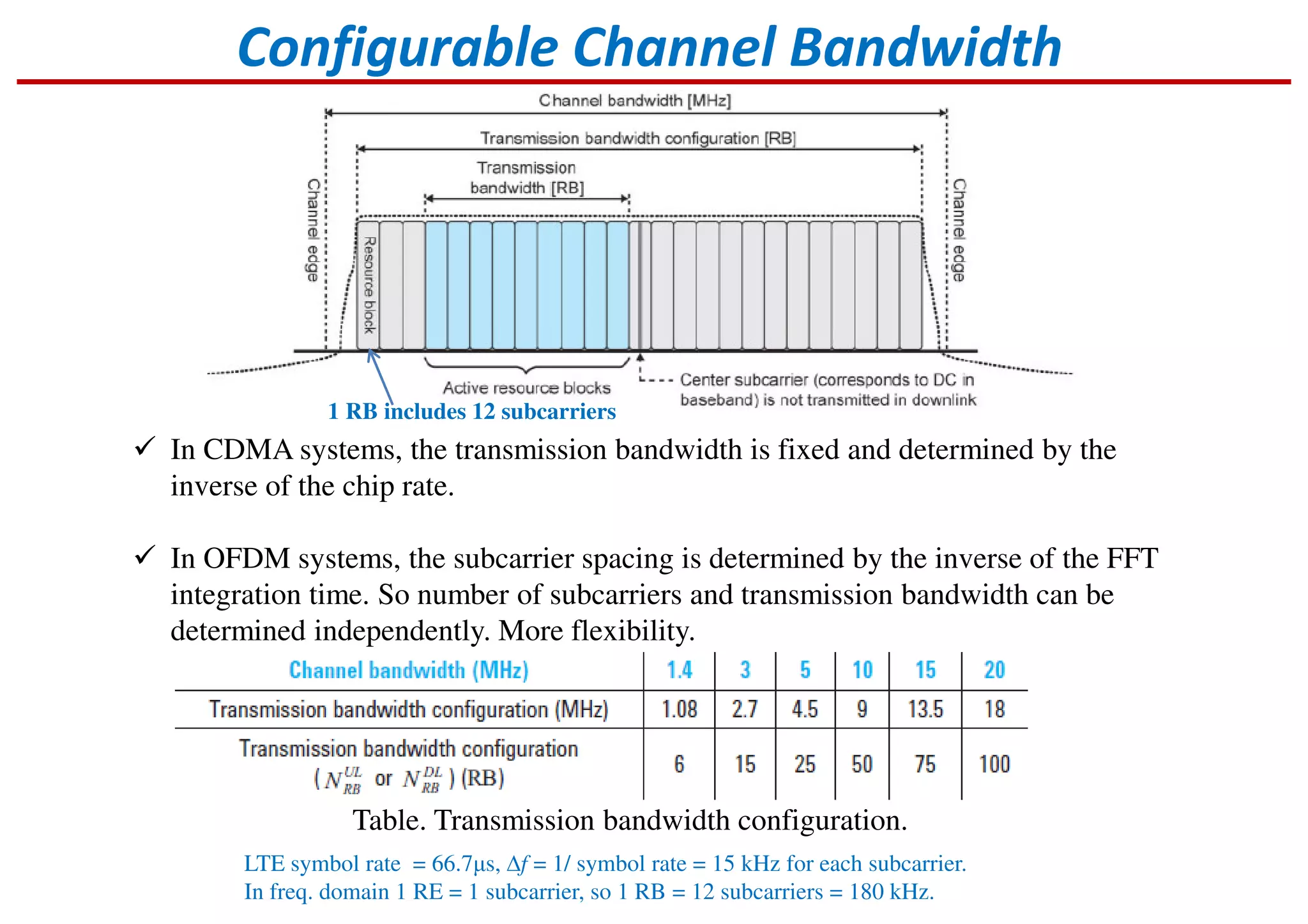
Description of FDD and TDD frame structures, including slots and subframes.Definition of resource elements and blocks, and their significance in channel configuration.