Guwahati Escorts Service Girl ^ 9332606886, WhatsApp Anytime Guwahati
Optical amplifiers
1. Optical Amplifiers
With the demand for longer transmission lengths, optical amplifiers have become an essential
component in long-haul fiber optic systems. Semiconductor optical amplifiers (SOAs), erbium
doped fiber amplifiers (EDFAs), and Raman optical amplifiers lessen the effects of dispersion
and attenuation allowing improved performance of long-haul optical systems.
Semiconductor Optical Amplifiers
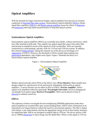
Semiconductor optical amplifiers (SOAs) are essentially laser diodes, without end mirrors, which
have fiber attached to both ends. They amplify any optical signal that comes from either fiber
and transmit an amplified version of the signal out of the second fiber. SOAs are typically
constructed in a small package, and they work for 1310 nm and 1550 nm systems. In addition,
they transmit bidirectionally, making the reduced size of the device an advantage over
regenerators of EDFAs. However, the drawbacks to SOAs include high-coupling loss,
polarization dependence, and a higher noise figure. Figure 1 illustrates the basics of a
Semiconductor optical amplifier.
Figure 1 - Semiconductor Optical Amplifier
Modern optical networks utilize SOAs in the follow ways: Power Boosters: Many tunable laser
designs output low optical power levels and must be immediately followed by an optical
amplifier. ( A power booster can use either an SOA or EDFA.) In-Line Amplifier: Allows
signals to be amplified within the signal path. Wavelength Conversion: Involves changing the
wavelength of an optical signal. Receiver Preamplifier: SOAs can be placed in front of
detectors to enhance sensitivity.
EDFAs
The explosion of dense wavelength-division multiplexing (DWDM) applications make these
optical amplifiers an essential fiber optic system building block. EDFAs allow information to be
transmitted over longer distances without the need for conventional repeaters. The fiber is doped
with erbium, a rare earth element, that has the appropriate energy levels in their atomic structures
for amplifying light. EDFAs are designed to amplify light at 1550 nm. The device utilizes a 980
nm or 1480nm pump laser to inject energy into the doped fiber. When a weak signal at 1310 nm
2. or 1550 nm enters the fiber, the light stimulates the rare earth atoms to release their stored energy
as additional 1550 nm or 1310 nm light. This process continues as the signal passes down the
fiber, growing stronger and stronger as it goes. Figure 2 shows a fully featured, dual pump
EDFA that includes all of the common components of a modern EDFA.
Figure 2 - Block Diagram of an EDFA
The input coupler, Coupler #1, allows the microcontroller to monitor the input light via detector
#1. The input isolator, isolator #1 is almost always present. WDM #1 is always present, and
provides a means of injecting the 980 nm pump wavelength into the length of erbium-doped
fiber. WDM #1 also allows the optical input signal to be coupled into the erbium-doped fiber
with minimal optical loss. The erbium-doped optical fiber is usually tens of meters long. The 980
nm energy pumps the erbium atom into a slowly decaying, excited state. When energy in the
1550 nm band travels through the fiber it causes stimulated emission of radiation, much like in a
laser, allowing the 1550 nm signal to gain strength. The erbium fiber has relatively high optical
loss, so its length is optimized to provide maximum power output in the desired 1550 nm band.
WDM #2 is present only in dual pumped EDFAs. It couples additional 980 nm energy from
Pump Laser #2 into the other end of the erbium-doped fiber, increasing gain and output power.
Isolator #3 is almost always present. Coupler #2 is optional and may have only one of the two
ports shown or may be omitted altogether. The tap that goes to Detector #3 is used to monitor the
optical output power. The tap that goes to Detector #2 is used to monitor reflections back into the
EDFA. This feature can be used to detect if the connector on the optical output has been
disconnected. This increases the backreflected signal, and the microcontrolled can set to disable
the pump lasers in this event, providing a measure of safety for technicians working with
EDFAs. Figure 3 shows a two-stage EDFA with mid-stage access. In this case, two single-stage
EDFAs are packaged together. The output of the first stage EDFA and the input of the second
stage EDFA are brought out the user. Mid-stage access is important in high performance fiber
optic systems. To reduce the overall dispersion of the system, dispersion compensating fiber
(DCF) can be used periodically. However, problems can arise from using the DCF, mostly the
insertion loss reaching 10 dB. Placing the DCF at the mid-stage access point of the two-stage
EDFA reduces detrimental effects on the system, and allows the users noticeable gain.
3. Figure 3 - Two-stage EDFA with Mid-stage Access
The optical input first passes through optical Isolator #1. Next the light passes through WDM #1,
which provides a means of injecting the 980 nm pump wavelength into the first length of erbium-
doped fiber. WDM #1 also allows the optical input signal to be coupled into the erbium-doped
fiber with minimal optical loss. The erbium-doped optical fiber is usually tens of meters long.
Like the fully feature, dual pumped EDFA, the 980 nm energy pumps the erbium atoms into an
excited state that decays slowly. When light in the 1550 nm band travels through the erbium-
doped fiber it causes stimulated emission of radiation. As the optical signal gains strength, output
of the erbium-doped fiber then goes into the optical isolator #2, the output of which is available
to the user. Typically, a dispersion compensating device will be connected at the mid-stage
access point. The light then travels through isolator #3 and WDM #2, which couples additional
980 nm energy from a second pump laser into the other end of a second length of erbium-doped
fiber, increasing gain and output power. Finally, the light travels through isolator #4. Photons
amplify the signal avoiding almost all active components, a benefit of EDFAs. Since the output
power of an EDFA can be large, any given system design can require fewer amplifiers. Yet
another benefit of EDFAs is the data rate independence means that system upgrades only require
changing the launch/receive terminals. The most basic EDFA design amplifies light over a
narrow, 12 nm, band. Adding gain equalization filters can increase the band to more than 25 nm.
Other exotic doped fibers increase the amplification band to 40 nm. Because EDFAs greatly
enhance system performance, they find use in long-haul, high data rate fiber optic
communication systems and CATV delivery systems. Long-haul systems need amplifiers
because of the lengths of fiber used. CATV applications often need to split a signal to several
fibers, and EDFAs boost the signal before and after the fiber splits. There are four major
applications that generally require optical fiber amplifiers: power amplifier/booster, in-line
amplifier, preamplifier or loss compensation for optical networks. Below are detailed description
of each application. Power Amplifier/Booster Figure 4 illustrates the first three application for
optical amplifiers. Power amplifiers (also referred to as booster amplifiers) are placed directly
after the optical transmitter. This application requires the EDFA to take a large signal input and
provide the maximum output level. Small signal response is not as important because the direct
4. transmitter output is usually -10 dBm or higher. The noise added by the amplifier at this point is
also not as critical because the incoming signal has a large signal-to-noise ratio (SNR).
Figure 4 - Three Applications for an EDFA
In-Line Amplifiers In-line amplifiers or in-line repeaters, modify a small input signal and boost it
for retransmission down the fiber. Controlling the small signal performance and noise added by
the EDFA reduces the risk of limiting a system's length due to the noise produced by the
amplifying components. Preamplifiers Past receiver sensitivity of -30 dBm at 622 Mb/s was
acceptable; however, presently, the demands require sensitivity of -40 dBm or -45 dBm. This
performance can be achieved by placing an optical amplifier prior to the receiver. Boosting the
signal at this point presents a much larger signal into the receiver, thus easing the demands of the
receiver design. This application requires careful attention to the noise added by the EDFA; the
noise added by the amplifier must be minimal to maximize the received SNR. Compensating for
Loss in Optical Networks Inserting an EDFA before an 8 x 1 optical splitter increases the power
to almost +19 dBm allowing each of the eight output legs to provide +9 dBm, making the output
almost equal to the original transmitter power. The optical splitter alone has a nominal optical
insertion loss of 10 dB. The transmitter has an optical output of +10 dBm, meaning that the
optical splitter outputs without an EDFA would be 0 dBm. This output power would be
acceptable for most digital applications; however, in analog CATV applications this is the
minimal acceptable received power. Therefore, inserting the EDFA before the optical splitter
greatly increases the output power.
Figure 5 - Loss Compensation in Optical Networks
Wideband EDFAs Optical communication systems carrying 100 or more optical wavelengths
require and increase in the bandwidth of the optical amplifier to nearly 80 nm. Normally
employing a hybrid optical amplifier, consisting of two separate optical amplifiers, allows for
separate amplification, one for the lower 40 nm band and the second for the upper 40 nm band.
Figure 6 exemplifies the optical gain spectrum of a hybrid optical amplifier. The solid lines
illustrate the response of two individual amplifier sections. The dotted line, which has been
increased by 1 dB for clarity, shows the response of the combined hybrid amplifier.
5. Figure 6 - Optical Gain Spectrum of a Hybrid Optical Amplifier
Raman Optical Amplifiers
Raman optical amplifiers differ in principle from EDFAs or conventional lasers in that they
utilize stimulated Raman scattering (SRS) to create optical gain. Initially, SRS was considered
too detrimental to high channel count DWDM systems. Figure 7 shows the typical transmit
spectrum of a six channel DWDM system in the 1550 nm window. Notice that all six
wavelengths have approximately the same amplitude.
Figure 7 - DWDM Transmit Spectrum with Six Wavelengths
By applying SRS the wavelengths, it is obvious that the noise background has increased, making
the amplitudes of the six wavelengths different. The lower wavelengths have a smaller amplitude
than the upper wavelengths. The SRS effectively robbed energy from the lower wavelength and
fed that energy to the upper wavelength.
6. Figure 8 - Received Spectrum After SRS is on a Long Fiber
A Raman optical amplifier is little more that a high-power pump laser, and a WDM or
directional coupler. The optical amplification occurs in the transmission fiber itself, distributed
along the transmission path. Optical signals are amplified up to 10 dB in the network optical
fiber. The Raman optical amplifiers have a wide gain bandwidth (up to 10 nm). They can use any
installed transmission optical fiber. Consequently, they reduce the effective span loss to improve
noise performance by boosting the optical signal in transit. They can be combined with EDFAs
to expand optical gain flattened bandwidth. Figure 9 shows the topology of a typical Raman
optical amplifier. The pump laser and circulator comprise the two key elements of the Raman
optical amplifier. The pump laser, in this case, has a wavelength of 1535 nm. The circulator
provides a convenient means of injecting light backwards in to the transmission path with
minimal optical loss.
Figure 9 - Typical Raman Amplifier Configuration
Figure 10 illustrates the optical spectrum of a forward-pumped Raman optical amplifier. The
pump laser is injected at the transmit end rather than the receive end as shown in Figure 9. The
pump laser has a wavelength of 1535 nm; the amplitude is much larger than the data signals.
7. Figure 10 - Example of Raman Amplifier -- Transmitted Spectrum
As before, applying SRS makes the amplitude of the six data signals much stronger. The energy
from the 1535 nm pump laser is redistributed to the six data signals.
Figure 11 - Example of Raman Amplifier -- Received Spectrum