APM Welcome, APM North West Network Conference, Synergies Across Sectors
KYL-812 user manual
1. Shenzhen KYL Communication Equipment Co., Ltd
Shenz Co.
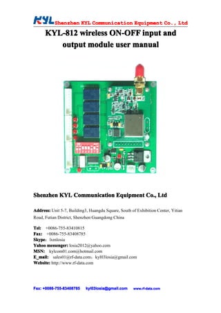
KYL-812 wireless ON-OFF input and
output module user manual
Shenzhen KYL Communication Equipment Co., Ltd
Address: Unit 5-7, Building3, Huangdu Square, South of Exhibition Center, Yitian
Road, Futian District, Shenzhen Guangdong China
Tel: +0086-755-83410815
Fax: +0086-755-83408785
Skype
Skype:lxmlosia
Yahoo messenger: losia2012@yahoo.com
MSN: kylcom01.com@hotmail.com
E_mail: sales01@rf-data.com;kyl03losia@gmail.com
Website: http://www.rf-data.com
Fax: +0086-755-83408785
+0086- 755-83408785 kyl03losia@gmail.com www.rf-data.com
2. Shenzhen KYL Communication Equipment Co., Ltd
Shenz Co.
KYL-812 wireless ON-OFF input and output module is a wireless
transmission equipment with four 4-channel DI and 4-channel relay DO.
I. Function
4 channel ON-OFF DI and DO transmitting timely. The 4 channel
ON-OFF condition for the transmitting equipment can be output timely
at the receiver equipment. That is the ON-OFF condition for the
transmitting equipment is shut down, while the ON-OFF condition will
be shut down at the receiver equipment; and the transmitting
equipment is disconnect, while the receiver equipment will disconnect.
The following is the schematic diagram of the ON-OFF transmission.
Schematic diagram
II Feature:
II、Feature:
1、 4-channel coupler isolated inputs, high reliability and stability.
2、 4-channel relay dry contact output, contact current is 30V 1A.
3、 4-channel 5V voltage output。
4、 collocate wireless data transmission module with 2-3km.
Fax: +0086-755-83408785
+0086- 755-83408785 kyl03losia@gmail.com www.rf-data.com
3. Shenzhen KYL Communication Equipment Co., Ltd
Shenz Co.
Working frequency 433MHz(400-470MHz);
RF power: 500mW;
Receive sensitivity: -120dBm
5、 Receive current: 30mA; transmitting current: 300mA
6、 Power supply: DC 9-15V
7、 Size: 82mm*82mm
III. DIP switch definition
III.
DIP8:Working mode choosing:
ON—send the inputting conditions. The module will send the
inputting conditions of the 4-channel ON-OFF
OFF—send timely every 1s or 2s; principal equipment will send
the 4-channel input condition to the subordinate equipment
(non-realtime transmission)
DIP7:Principal and subordinate mode choosing under the timing mode:
ON—subordinate equipment, OFF—principal equipment
DIP6:Sending interval choosing under the timing mode:
ON—slow(2s one time), OFF—fast(1s one time)
DIP5:No definition
DIP1-4:Channels choosing (max 16 channels)
The following is the channel correspondence table for DIP switch 1-16:
Channel Channel Channel Channel
DIP NO. DIP NO. DIP NO. DIP NO.
No. No. No. No.
Fax: +0086-755-83408785
+0086- 755-83408785 kyl03losia@gmail.com www.rf-data.com
4. Shenzhen KYL Communication Equipment Co., Ltd
Shenz Co.
1 5 9 13
2 6 10 14
3 7 11 15
4 8 12 16
Note:
* Users generally use the inputting change sending mode, DIP7-ON;
* To avoid more than two remote control systems working at the same
time in one remote control range, the module for different system
should choose different channel (working frequency);
* Under the timing mode, it should be one subordinate equipment, and
one principal equipment;
* It should be effect by re-power on the module after changing the DIP
position.
VI. Connection Definition
Connection name Pin No. Definition Remarks
COM1 1 GND Grounding of power supply
2 VCC DC:9-15V
COM2 1 IN1 First group ON-OFF input
2 GND
3 IN2 Second group ON-OFF input
4 GND
5 IN3 Third group ON-OFF input
6 GND
Fax: +0086-755-83408785
+0086- 755-83408785 kyl03losia@gmail.com www.rf-data.com
5. Shenzhen KYL Communication Equipment Co., Ltd
Shenz Co.
7 IN4 Fourth group ON-OFF input
8 GND
COM3 1 GND First channel voltage controlling
2 LED1 output (5V)
3 GND Second channel voltage
4 LED2 controlling output (5V)
5 GND Third channel voltage
6 LED3 controlling output (5V)
7 GND Fourth channel voltage
8 LED4 controlling output (5V)
COM4 1 OUT1 First channel relay dry contact
2 output
3 OUT2 Second channel relay dry contact
4 output
5 OUT3 Third channel relay dry contact
6 output
7 OUT4 Fourth channel relay dry contact
8 output
V: Using method
1、First according to your using requirement, setting the DIP switch and
connecting the power(12V), the switch input and the correspondence
switch output by following the above instruction.
2、Turn on the power
3、 is the contact sending mode and the working channel is No.1 default.
It
Fax: +0086-755-83408785
+0086- 755-83408785 kyl03losia@gmail.com www.rf-data.com
6. Shenzhen KYL Communication Equipment Co., Ltd
Shenz Co.
IV. Exterior sketch map
Fax: +0086-755-83408785
+0086- 755-83408785 kyl03losia@gmail.com www.rf-data.com