SlideShare a Scribd company logo
1 of 10
Download to read offline
1048 SSSAJ: Volume 72: Number 4 • July–August 2008
SOILPHYSICS
Soil Sci. Soc. Am. J. 72:1048-1057
doi:10.2136/sssaj2007.0022
Received 15 Jan. 2007.
*Corresponding author (bagav@unipa.it).
© Soil Science Society of America
677 S. Segoe Rd. Madison WI 53711 USA
All rights reserved. No part of this periodical may be reproduced or
transmitted in any form or by any means, electronic or mechanical,
including photocopying, recording, or any information storage and
retrieval system, without permission in writing from the publisher.
Permission for printing and for reprinting the material contained
herein has been obtained by the publisher.
The hydraulic conductivity of saturated soil (Ks) is one of the
most important soil properties controlling many hydro-
logical processes. This property depends on soil texture and
structure and therefore can vary in space, in time, and with the
direction of flow. In anisotropic soils, the Kv of a given volume
of soil differs from the Kh of the same volume of soil (Beckwith
et al., 2003). The anisotropy of Ks is not routinely determined,
probably due to the lack of practical and well tested measure-
ment methodologies.
The constant-head laboratory permeameter (CHP)
method (Klute and Dirksen, 1986) is widely used for measur-
ing Ks. Two approaches can be applied to measure the Kv and
Kh values of undisturbed soil samples by the CHP method. In
particular, soil may be sampled by pushing cylinders in both
the vertical and the horizontal direction into exposed soil sur-
faces. In this case, the measurement of Kv and Kh is performed
on different soil cores (TCM; Dabney and Selim, 1987; Bathke
and Cassel, 1991). The CM (Bouma and Dekker, 1981) and
the MCM (Beckwith et al., 2003) may be applied to obtain
a single soil sample for the measurement of both Kv and Kh.
With the CM, a cube of soil is carved out in situ by gently
removing soil along its sides. All but two opposing faces of the
cube of soil are then encased in a slurry of gypsum. When the
gypsum has set, the cube of soil and the encasing gypsum are
removed from the pit and the soil sample is moved to the labo-
ratory for measuring the rates of water flow between the open
sides, yielding a measurement of Kv. The faces are then sealed
with gypsum and the cube is rotated. Two faces at right angle
to the original faces are exposed and Kh is measured. With the
MCM, the top and bottom of the cube are also encased in the
gypsum before moving the sample to the laboratory. All faces
receive the same treatment to reduce the risk of smearing of the
faces used for the first Ks test (Beckwith et al., 2003). Molten
wax has been used instead of gypsum to prepare the casing
(Surridge et al., 2005).
In principle, the anisotropy measurements obtained with
the cube methods (CM, MCM) should be more reliable than
the ones deduced with the TCM. A reason is that only anisot-
ropy at the scale of the measurement volume is expected to
affect the Kv and Kh data obtained on a single soil sample
whereas both anisotropy and small scale heterogeneity may
influence the Ks data collected on different cores (Beckwith et
V. Bagarello*
A. Sgroi
Dipartimento di Ingegneria e Tecnologie Agro-
Forestali
Facoltà di Agraria
Università degli Studi
Viale delle Scienze
90128
Palermo
Italy
Testing Soil Encasing Materials for Measuring
Hydraulic Conductivity of a Sandy-Loam Soil by
the Cube Methods
The Cube Method (CM) and the Modified Cube Method (MCM) were developed for measur-
ing vertical (Kv) and horizontal (Kh) saturated hydraulic conductivity of a single soil sample. By
these methods, a cube of soil is carved out in situ and a suitable material is applied to enclose
the cube in a tightly fitting casing before moving the sample to the laboratory. Problems may
be associated with the use of gypsum, originally used to encase soil. The suitability of molten
wax and expandable polyurethane foam to encase a soil cube was tested for a sandy-loam soil.
Wax-treated samples yielded lower conductivity results than untreated samples by a maximum
factor of 3.7. The observed discrepancies were attributed, at least in part, to soil pore obstruction
phenomena caused by wax. Using foam to fill a gap 60% full and partially preventing leakage of
expanded foam from the gap was found to be appropriate to reach the following objectives: (i)
filling completely the gap after foam expansion, (ii) preventing flow at the boundary between the
foam cast and a smooth surface, (iii) minimizing both dry and wet soil compaction phenomena
during foam expansion, (iv) minimizing foam intrusion into exposed pores of 1.0 × 10⁻³ to
3.0 × 10⁻³ m (intrusion depth ≤ 2.0 × 10⁻³ m), and (v) allowing removal of any intrusion by
the detachment of the set foam from the treated surface. Applying foam to collect undisturbed
soil samples yielded Kv results (7.41 × 10⁻⁵– 1.67 × 10⁻⁴ m s−1) falling in the range of a larger
number of previously measured conductivities (2.06 × 10⁻⁵– 2.03 × 10⁻⁴ m s−1), and it showed
that Kv was 2.3 times larger than Kh. In conclusion, using wax is not recommended to obtain fully
representative soil samples. Foam was a promising encasing material for the investigated soil.
Abbreviations: CHP, constant-head laboratory permeameter; CM, Cube Method; Kh, horizontal saturated
hydraulic conductivity; Kv, vertical saturated hydaulic conductivity; MCM, Modified Cube Method; NT,
untreated soil cores; SFH, simplified falling head; TCM, Two-Core Method; W, wax-treated soil cores.
SSSAJ: Volume 72: Number 4 • July–August 2008 1049
al., 2003). An additional reason is that, in several cases, more
representative soil samples for a selected site may probably be
obtained by the cube methods than by the TCM. When a
cylinder is used to collect a soil core, shattering or puddling
and compaction phenomena may occur during sampling (e.g.,
Bouma et al., 1976; Topp et al., 1993) and short-circuiting flow
along the edge of the soil core may occur during the Ks test due
to the presence of gaps between the soil column and the rigid
cylinder (e.g., Cameron et al., 1990; Hoag and Price, 1997).
The occurrence of these phenomena can yield unrepresentative Ks
results. On the other hand, the soil volume used in the CM does
not receive any particular disturbance before the Ks tests. Moreover,
the cube is enclosed in a tightly fitting cast that conforms to any
irregularities in the exposed soil surface before hardening and
prevents edge flow (Bouma and Dekker, 1981; Beckwith et al.,
2003; Surridge et al., 2005). Probably, the cube methods cannot
be applied in loose, unstructured soils since a stable volume of soil
of a pre-established shape cannot be prepared.
Desired characteristics of a soil cube casing include the
following: (i) rigidity, to minimize the risk of altering the struc-
ture of the sampled soil during detachment, transport, and
measurement stages; (ii) stability, so that the contact with water
does not weaken the casing; (iii) impermeability, in order that
all terms of the Darcy’s law can be defined unambiguously (in
particular, the cross-sectional area of the porous medium sub-
jected to a given hydraulic gradient should be clearly definable);
and (iv) workability, to easily seal or expose soil cube faces.
Moreover, the encasing soil material should not result in changes
(i.e., compaction, pore occlusion) to the exposed soil volume.
Selection of a soil encasing material for application of the
cube methods is complicated by the fact that different authors,
also working with gypsum or wax for different purposes than
measuring Ks, have suggested possible problems with both
materials for several reasons, including workability of the mate-
rial, weakening of the casing after wetting, and obstruction of
exposed pores (Frasier and Keiser, 1993; Bagarello et al., 2005;
Surridge et al., 2005). However, more detailed investigations
are necessary given that a specific evaluation of the suitability
of wax for Ks measurement by the cube methods is lacking.
One alternative material for use as a CM or MCM soil cas-
ing is expandable polyurethane foam. Foams of this type have
been used to measure other soil physical and hydraulic properties
(Muller and Hamilton, 1992; Mendoza and Steenhuis, 2002).
However, little is known about the use of this type of foam for
measuring Kv and Kh by cube methods. The objective of this
investigation was to test the suitability of both molten wax and
expandable polyurethane foam for measuring Kv and Kh of a
sandy-loam soil by encasing a cube of soil (cube methods).
SOIL ENCASING MATERIALS
Gypsum was the first material used for a measurement of Ks by
the CM (Bouma and Dekker, 1981). Bouma et al. (1976) observed
flow occurrence between the walls of the soil and the gypsum casing
after a long contact period (i.e., several weeks) but not after a short
period (i.e., 1 d). Bouma and Dekker (1981) suggested that direct
contact between water and gypsum for periods of several hours may
result in weakening of the gypsum but they also noted that the con-
tact between gypsum and soil was tight enough to prevent boundary
flow during a Ks measurement. Zobeck et al. (1985) and Caris and
Van Asch (1991) did not report any specific problem associated with
the use of gypsum in their applications of the CM. However, Caris
and Van Asch (1991) also reported, in generic terms, that measur-
ing Ks in two directions in the same sample as described by Bouma
and Dekker (1981) posed too many problems. In practice, different
proportions of water and gypsum may be used to prepare the slurry.
If a relatively large amount of water is used, the slurry can enter the
exposed soil pores and hardening of the gypsum may take a long time.
If a relatively small amount of water is used, working with the gypsum
becomes difficult and the risk of forming zones of reduced contact
between the exposed soil surfaces of the cube and the gypsum casing
may increase. Neither Bouma and Dekker (1981) nor Beckwith et
al. (2003) gave details on the amounts of water and gypsum used to
prepare the slurry. Surridge et al. (2005) noted that weakening and
workability problems were associated with the use of gypsum for the
application of the MCM. Bagarello et al. (2005) found increasing
percolation rates during some Ks tests due to the development of small
incisions on the inner surface of a casing when using a gypsum slurry
45% by weight of water and 55% of gypsum. Moreover, water drops
appeared on the external surface of the casing during Ks measure-
ment. Very small amounts of water flow through the gypsum were
also observed with a quite dense gypsum product, like plaster used
on walls in buildings (A.J. Baird, personal communication, 2004).
Altogether, the results summarized above justify the search for an
alternative soil encasing material.
Molten wax is an alternative material (Surridge et al., 2005).
Hoag and Price (1997) noted that the wax penetrated an undisturbed
peat by about 2.0 × 10⁻³ m, ensuring a tight seal between the peat
and the pipe. In an investigation by Bagarello et al. (2005), treating
the lateral side of a cylindrical soil sample with molten wax was simi-
lar, in terms of Kv results, to simply enclosing the soil sample into a
PVC cylinder. One of the possible interpretations of this result was
that wax penetrated exposed pores to a short distance, not affecting
the Kv results. A short depth of penetration would suggest that a rep-
resentative measurement of Ks might be obtained with the cube meth-
ods by removing a thin layer of soil from the surface of the sample, to
eliminate any pore obstruction before performing the measurement.
However, pore occlusion phenomena may be more appreciable, given
that Dexter (1976) used molten wax for filling pores of >1.0×10⁻³
m to a depth of several centimeters. According to Frasier and Keiser
(1993), occlusion phenomena depend on the temperature of the mol-
ten wax. In particular, cooler wax will not flow into the pores of the
surrounding soil, but hot wax may. The optimum temperature is as
close to the solidifying temperature as possible. At the optimum tem-
perature, the wax will begin to solidify immediately on contact with
the soil surface. However, control of the temperature of the molten
wax may be difficult, especially in the field. Surridge et al. (2005)
applied the wax by dipping successive sides of a cube of peat into
molten wax until the entire cube was encased in a 5.0 × 10⁻³ m layer
of wax, probably to minimize occlusion phenomena of the exposed
pores. This method of encasing a cube does not seem usable with
most mineral soils, due to the risk of altering the soil cube during its
detachment and transport. Another phenomenon potentially compli-
cating the preparation of the casing is shrinking of the wax during
cooling (Frasier and Keiser, 1993). The above results suggest that wax
is not a suitable material to encase a soil cube for Ks measurement.
However, the suitability of wax for measuring Ks of a mineral soil with
the cube methods was not tested.
1050 SSSAJ: Volume 72: Number 4 • July–August 2008
Expandable polyurethane foam has been used with the excava-
tion method to obtain soil bulk density data (Muller and Hamilton,
1992; Page-Dumroese et al., 1999; Brye et al., 2004) and with the
hillslope infiltrometer to partially encase a soil block exposed in situ
(Mendoza and Steenhuis, 2002). The foam is waterproof and it grows
hard after 8 to 24 h of curing (Brye et al., 2004). Moreover, it is rela-
tively easy to apply and to incise after hardening. Therefore, the foam
seems to have the potential to encase in the field a soil volume usable
in the laboratory for a two directional measurement of Ks. According
to Muller and Hamilton (1992), soil particles remain attached to the
cast when it is removed from the hole prepared for bulk density deter-
mination. This may suggest that the contact between the foam and
the soil should be assured but this hypothesis has to be specifically
tested before considering the foam as being a suitable material for
Ks measurement. According to Brye et al. (2004), expandable poly-
urethane foam typically expands to several times the volume of foam
initially injected and, therefore, it is usually recommended to fill a gap
only 50% full to allow the foam to expand on its own to completely
fill the gap without much excess to cut off and remove. However, the
excavation method for bulk density determination has been applied
by filling the cavity completely full and placing a cardboard plate with
a weight across the surface to ensure a complete expansion of the foam
into all microtopographic variations in the outer surface of the exca-
vated cavity (Muller and Hamilton, 1992; Brye et al., 2004). Filling
a cavity, such as the void space within a box placed around the soil
cube (Bouma and Dekker, 1981), with a relatively small amount of
foam may preclude complete covering of the exposed soil surfaces.
Instead, using a large or a relatively large amount of foam may be
important to improve both the rigidity of the casing and the contact
between the casing and the treated soil surfaces. However, pressures
may also develop at the interface between the foam and the soil dur-
ing foam expansion. These pressures may have an adverse effect on
the structural characteristics of the sampled soil volume and hence
on the reliability of the measured Ks value. Expanding foam might
also penetrate exposed pores. Therefore, it is necessary to improve our
knowledge on both the soil compaction and pore occlusion phenom-
ena induced by foam expansion to establish the possibility of using
this material for the preparation of a soil casing.
MATERIALS AND METHODS
Field Site
A flat area supporting a citrus orchard was used for this study
at the Faculty of Agriculture of the Palermo University. The study
was conducted on a soil (Typic Rhodoxeralf) having a relatively high
sand (>50%) and gravel (13%) content. According to the USDA
classification (Gee and Bauder, 1986), most textures of 12 replicated
soil samples were sandy-loam. The experiments were performed in the
period ranging from October 2004 to November 2006, collecting the soil
samples immediately before conducting an experiment. The experimental
site was not disturbed from 2002 until the experiments were completed.
The original cube method was intended specifically for clay soils
to avoid problems including puddling of the sidewalls and closure of
the macropores due to drilling of auger holes, unrepresentativeness of
Ks results obtained with small core samples, and changes in macrop-
orosity due to pushing cylinders into the soil (Bouma and Dekker,
1981). For the soil considered in this investigation, sidewall smear-
ing may affect the Ks values obtained with the Guelph permeame-
ter method (Bagarello, 1997), and the size of the core influences the
measured Ks by the CHP method (Bagarello and Provenzano, 1996).
Moreover, soil structure alteration phenomena can occur due to push-
ing a cylinder into the soil. Therefore, the cube methods are attractive
to improve the reliability of the Ks data for this sandy-loam soil.
Molten Wax
The effect of molten wax on Ks measurement was evaluated by
a comparison between the Ks results of wax-treated and untreated
soil surfaces. Interpreting the results of a single comparison may be
difficult because many factors influence the measured Ks values (e.g.,
Reynolds et al., 2000). Therefore, three different experiments were
performed, varying soil collection and sample treatment procedures
among the experiments, in an attempt to reduce the uncertainties in
the interpretation of the Ks results.
Experiment No. 1
The MCM and the TCM were compared to determine the
anisotropy of Ks. Five spots of 1.0 m × 1.0 m were randomly selected
within a 10-m2 area. The following soil samples were obtained at each
spot after removing the upper layer, approximately 0.10 m thick: (i)
a cubic sample with a side of 0. 13 m, encased in a casing of wax (Fig.
1a to 1c), and (ii) a vertically oriented and a horizontally oriented
soil core, collected by using stainless steel cylinders (diameter = 0.085
m, height = 0.115 m) (Fig. 1d). The cubic sample was obtained by
exposing in situ a 0.15-m-high soil volume. A square wooden box
with a side of 0.17 m, open at two opposing ends, was placed around
the exposed prism of soil before pouring the molten wax to encase
the soil. The walls of the box were hinged to allow detachment of
the sidewalls from the casing containing the soil cube (Bouma and
Dekker, 1981). After the wax had set, the prism was detached and it
was turned upside down. A layer of soil of 0.02 m was removed from
the bottom end of the sample and molten wax was poured to com-
pletely encase the soil sample. Before saturated hydraulic conductivity
measurement, two opposing faces of the wax casing were removed by
a heated knife. The exposed soil pores appeared to be, at least partially,
soaked with wax. Therefore, a layer of approximately 0.01 m of soil
was removed from both exposed faces. Then, Kv was determined. Two
or 3 d later, the faces were resealed with wax and the cube was turned
through 90°. Two other opposing faces were exposed and Kh was mea-
sured after removing a layer of approximately 0.01 m of soil from
both exposed faces. Each soil sample (both cubic and cylindrical) was
placed on a nylon guard cloth and a wire net to support the weight of
the soil before starting the Ks test.
Experiment No. 2
Five spots of 1.0 m × 1.0 m were randomly selected within an
area of approximately 10 m2 and stainless steel cylinders were used to
collect two undisturbed soil cores (diameter = 0.085 m, height = 0.115
m) at each spot, after removing the upper 0.10 m of soil. For each spot,
a randomly chosen soil core was treated with wax (W soil core). In
particular, the soil core (maintained in the stainless steel cylinder) was
placed on a polystyrene disc (diameter = 0.085 m, height = 0.02 m) and
a PVC pipe 0.118-m-diameter × 0.15-m-high was placed around the
core. Molten wax was poured into the PVC pipe, fully covering the soil
core by wax. After that wax had set, the sample was turned upside down,
the polystyrene disc was removed, and the exposed soil surface (bottom
of the soil core) was covered by a 0.02-m-thick layer of molten wax. A
few days after the treatment, the upper and lower faces of the wax were
removed by a heated knife. A thin layer of soil (5.0 × 10⁻³ m) was
also removed from both faces of the core by gently using a sharp knife,
SSSAJ: Volume 72: Number 4 • July–August 2008 1051
notwithstanding that the soil surface did not appear to
be soaked with wax in this experiment. The other soil
core that was also used for the first experiment was not
treated with wax (NT soil core). The Kv value of each
W and NT soil core was measured.
Experiment No. 3
Five spots of 1 m × 1 m were randomly selected
within an area of approximately 15 m2. Both the
CM and the MCM were applied to collect two dif-
ferent soil samples at each spot, after removing the
upper 0.03 m of soil. Each soil sample (0.13 × 0.13 ×
0.15 m3) was carved out in situ by removing the soil
along its sides. A square wooden box with a side of
0.17 m was placed around the soil prism and molten
wax was poured into the space between the walls of
the box and the exposed surfaces of the soil sample.
For the soil samples collected with the MCM, both
the upper and the lower face of the cube were also
coated with wax. The upper and the bottom end
of the soil sample collected with the CM were not
sealed with wax. Instead, a piece of cardboard was
placed on the upper face of the prism of soil to pre-
serve the surface of the sample from contact with the
molten wax used to prepare the casing. The Kv value
of each collected soil sample was measured in the
laboratory. The upper and lower faces of each MCM
sample were exposed before measuring Kv, by using
a heated knife. For this experiment, the soil surface
did not appear to be soaked with wax and a layer of
soil was not removed from the sample. For the CM
samples, the already open faces (i.e., not treated with
wax) were used to measure Kv.
Experiments No. 1 through No. 3
For all experiments, an attempt to use mol-
ten wax at a temperature as close to the solidifying
temperature as possible was performed (Frasier and
Keiser, 1993). The conductivity was measured in the
laboratory by the CHP method (Fig. 1e) (Klute and
Dirksen, 1986). The soil was not saturated before performing the Ks
test because most natural and man-made infiltration processes result
in significant air entrapment within the porous medium (Reynolds,
1993). In other words, the so-called field-saturated hydraulic conduc-
tivity, or satiated conductivity, was considered in this investigation
given that the lack of a complete filling of the pores between soil par-
ticles in a satiated soil is caused by the entrapment of air as water
enters the soil. In addition, it should be noted that the term field-
saturated hydraulic conductivity has been used in the literature for
other laboratory experiments (e.g., Odell et al., 1998). The constant
thickness of the water layer above the surface varied between 0.014
and 0.020 m, depending on the soil sample. Drained water volumes
were monitored for ≥ 6 h. Measurement of outflow started at the
beginning of the experiment to detect occurrence of flow stabiliza-
tion. The data corresponding to a stable outflow process were used to
calculate Ks. For all experiments, the volumetric soil water content at
the time of sampling, θi, was determined gravimetrically. The mean
value of θi was equal to 0.190 m3m−3 (coefficient of variation, CV =
0.075, sample size, N = 10) for Exp. no.1, 0.193 m3 m−3 (CV = 0.284,
N = 5) for Exp. 2, and 0.216 m3 m−3 (CV = 0.024, N = 5) for Exp. 3.
According to Iovino (1998), in the sampled area, the soil water con-
tent corresponding to the field capacity, FC (i.e., pressure head value,
h = −0.033 MPa), and the permanent wilting point, PWP (i.e., h =
-1.5 MPa), is equal to 0.256 m3 m−3 and 0.140 m3 m−3, respectively.
Therefore, all experiments were performed in a soil having intermedi-
ate water content between the FC and PWP water contents.
Polyurethane Foam
Different experiments were performed to evaluate contact of
foam with a smooth surface, foam expansion, foam induced dry- and
wet-soil compaction, and foam intrusion into exposed pores. An
additional experiment was performed to test use of foam in the field.
Mungo Swiss Quality (mungo, Italy, Padova, www.mungo.it) pres-
surized cans of 750 mL, with a reported volume of 50 L of expanded
foam, were used in this investigation1.
Fig. 1. Field and laboratory application of the Modified Cube Method with wax and the
Two-Core Method (TCM): a) soil prism encased in a casing of wax in the field; b)
encased soil sample in the laboratory after removing the wooden box; c) exposed soil
surface; d) collection of soil cores for the application of the TCM; e) application of
the Constant-Head Permeameter method to a cubic soil sample.
1 Mention of a product does not constitute endorsement by the
authors or the University of Palermo.
1052 SSSAJ: Volume 72: Number 4 • July–August 2008
Foam Contact and Expansion
An experiment was performed to evaluate the ability of polyure-
thane foam to provide a good contact with a smooth surface and to
quantify foam expansion. A PVC cylinder (diameter = 0.094 m, height
= 0.114 m) open at both ends was placed on a moist sheet of blotting
paper and a small quantity of water was sprayed on the inner walls of
the cylinder. A pre-established amount of foam was injected into the
cylinder. Then, a moist sheet of blotting paper, a wooden tablet and a
weight of 70–80 N were placed on the top of the cylinder. Different
cylinders were filled with different volumes of foam, equal to 20, 40,
60, and 80% of the volume of the cylinder, respectively. Two PVC
cylinders were filled with a given amount of foam to obtain two sets
(set 1 and set 2) of filled cylinders. Two additional cylinders were filled
20% and 50% full, respectively, without placing any weight on the
top (set 3). For all sets, the foam was left to cure for two or 3 d. The
PVC cylinders of set 1 were cut by a heated knife and removed, leav-
ing a mold of foam that was examined visually. Cylinders of sets 2 and
3 were used to test occurrence of edge flow phenomena. Expanded
foam was removed from the top of the cylinder to leave a 0.03-m-high
space that was maintained partially filled by water (water layer thick-
ness = 0.025 m) for at least 3 d. A funnel and a small container were
placed below each cylinder to collect percolated water. For each cylin-
der used in the investigation, the volume of the expanded polyurethane
foam was also determined by volume displacement of water in a large
glass container (Muller and Hamilton, 1992).
Foam Induced Soil Compaction
An experiment was performed using air-dried soil passing a 2.0
× 10−3 m sieve and packed into 15 Plexiglas tubes (i.d. = 0.094 m,
height = 0.5 m). A nylon guard cloth and a wire net were connected
to the base of the tube to support the weight of the soil. The soil in
the tubes was compacted manually and small amounts of soil were
added during compaction to obtain a final height of the soil sample
of exactly 0.5 m, as described by Bagarello et al. (2006). For each
tube, the dry bulk density, ρb, the initial volumetric soil water con-
tent, θi, and the volumetric saturated soil water content were deduced
(Bagarello et al., 2004, 2006).
A PVC disk of 0.15 mm thickness and 94 mm diameter was
placed on top of the soil sample. A Plexiglas tube (i.d. = 0.094 m,
height = 0.150 m), covered internally with plastic wrap, was firmly
connected to the top of the soil column tube. The interior tube and
top PVC surfaces were spray-moistened just before foam was injected
to fill a pre-established fraction of the volume above the soil sample.
Then, a rectangular wooden tablet was secured tightly to the top of
the short tube using iron wire (Fig. 2, right). By this procedure, the
foam-induced pressure on the soil surface was maximized. For six ran-
dom samples, 30% of the volume above the soil surface was initially
filled by foam (03AV samples). For another six random samples, 60%
of the volume was filled (06AV samples). Three samples were left
uncovered (00AV samples). The cured foam was later removed and
its length was measured.
The Kv value of each soil sample was measured by the transient
simplified falling head (SFH) technique (Bagarello et al., 2004, 2006).
Before applying SFH, a 0.01 m layer of soil was gently scraped off the
top for three 03AV samples and three 06AV samples. These samples
are denoted by adding ‘-S’ (03AV-S and 06AV-S). For the remaining
nine samples, the soil surface was not altered. These samples retained
the notation 03AV and 06AV. An estimate of α* = 12 m−1 (Elrick and
Reynolds, 1992) was used to calculate Kv.
Wet soil conditions at the time of the Ks measurement and some
foam leakage from the confined space during foam expansion may
be anticipated in field use of the method. Therefore, another experi-
ment was conducted to represent these conditions. Soil from the first
compaction experiment (described above) was reused. It was air dried,
passed again through a 2-mm sieve, and packed into 12 columns.
The columns were saturated from the top and then allowed to freely
drain for 3 d. Their water content was determined gravimetrically,
PVC disks were again placed on the soil surface, and Plexiglas tubes
attached (Fig. 2, left). Elastic bands were used (rather than wire) to
hold down the wood tablet and allow limited foam expansion. For
six random samples, foam was injected until 60% of the available
volume was filled. The other six samples were left uncovered. Cured
foam was removed. Again, 0.01 m of soil was scraped off the top
for three uncovered columns (00AV-W-S) and three foam-treated col-
umns (06AV-W-S). A hairdryer was used briefly to dry the exposed
soil before removing it. The soil surface of the other samples (00AV-W
and 06AV-W) was neither scraped nor dried. The SFH technique was
used to measure Kv for all these samples.
Foam Intrusion into Exposed Pores
The experimental procedure was similar to that used for the dry
soil (first) foam induced soil compaction experiment. In this case,
however, the soil in the tube was gently wetted to a depth of approxi-
mately 0.06 to 0.07 m and some vertical pores (six with a diameter of
1.0 × 10⁻³ m, four of 2.0 × 10⁻³ m and four of 3.0 × 10⁻³ m) were
drilled into the exposed soil surface to a depth of 0.05 m, 24 h after
wetting. Then, foam was injected directly on the soil surface, in the
space confined by the short Plexiglas tube, until 60% of the available
volume was filled. As described above, foam expansion outside the
confined space after injection was totally prevented (wire) for three
samples and partially prevented (elastic bands) for the other three
samples. The foam plug was removed after >24 h of curing and both
the soil surface and the bottom of the plug were examined.
Using Foam in the Field
Foam was used to encase soil prisms within an area of 10 m2. A
few centimeters of soil were removed from the surface and a soil prism
(0.11 × 0.11 × 0.14 m3) was carved out (Fig. 3a). A wooden box (side
length = 0.17 m), its inner walls covered by plastic wrap to avoid
foam adhesion, was placed around the exposed soil prism. Water was
Fig. 2. Plexiglas tubes with the wooden tablet connected to the top
of the short tube by using elastic bands (left, foam leakage dur-
ing expansion partially prevented) and iron wire (right, foam
leakage during expansion totally prevented).
SSSAJ: Volume 72: Number 4 • July–August 2008 1053
sprayed on the inner walls of the box and foam was injected to fill 60
to 70% of the space between the box and the soil (Fig. 3b). Wood and
a weight of not more than 40 to 50 N were then used to confine foam
expansion (Fig. 3c). The cured cast with enclosed soil was detached
and turned upside down. A layer of soil 0.03-m thick was removed
from the bottom, which was then also encased in foam confined by
wood and a weight. Soil cores (0.05 m diam. by 0.05 m long) were
also collected to determine θi (0.134 m3m−3, CV = 0.064, N = 6). In
the laboratory, the cube was taken from the wooden box and the foam
was removed from both the top and bottom faces using a box cutter.
A nylon guard cloth and a wire net supported the weight of the soil
(Fig. 3d). The cube was then placed in the apparatus to measure Kv
(Fig. 1e), using 0.015 m ponded water depth. Calculation of Kv was
based on the ultimate steady discharge rate. The cube was allowed
to drain under gravity for 3 d. The exposed faces were resealed with
foam, the cube turned through 90°, two more faces exposed, and Kh
determined (Beckwith et al., 2003).
Summary and Statistical Analysis of Data
The statistical distribution of the Ks data was not checked in this
investigation due to the limited sample size for a particular data set.
However, the Ks results of the undisturbed soil samples were assumed
to be log-normally distributed since the statistical distribution of these
data is generally log-normal (Lee et al., 1985; Warrick, 1998). The
geometric mean and the associated CV were calculated to summarize
the Ks values of undisturbed soil (Lee et al., 1985). The Ks results
of the repacked soil samples were assumed to be normally distrib-
uted since unstructured soil was used, and the arithmetic mean and
the associated CV were used to summarize a given data set. Previous
investigations performed in the same experimental area with larger
sample sizes supported the choice of using a log-normal distribution
for the undisturbed soil results and a normal distribution for the
repacked samples (Bagarello and Provenzano, 1996; Bagarello et al.,
2000, 2004, 2006). Statistical comparison between means was con-
ducted using two-tailed t tests. The natural logs of the data were used
for the undisturbed soil sample results. A probability level, P = 0.05,
was used for all statistical comparisons.
RESULTS AND DISCUSSION
Molten Wax
In the Exp.1, the ratio between the mean values of Kv and
Kh was equal to 0.8 for the MCM treatment and to 1.1 for the
TCM treatment (Table 1). In both cases, these differences were
not statistically significant. Therefore, both treatments suggested
Fig. 3. Application of the Modified Cube Method with foam: (a) exposing the soil prism in the field; (b) filling part of the space between the
wooden box and the exposed soil volume with foam; (c) partially preventing foam leakage during expansion; and (d) placing a nylon guard
cloth and a wire net at the bottom of the cube to support the weight of the soil.
1054 SSSAJ: Volume 72: Number 4 • July–August 2008
that the anisotropy of Ks was not substantial given that relatively
low differences between Kv and Kh values were detected (e.g.,
Dabney and Selim, 1987). However, the MCM yielded lower
and more variable Kv and Kh results than the TCM. In particu-
lar, the two methods differed by a statistically significant factor
of 3.7 in the vertical direction and of 2.7 in the horizontal one.
In the Exp. no.2, the W soil cores yielded slightly lower (i.e.,
by 25%) and more variable results than the NT cores (Table 1).
However, the discrepancy between the two mean values of Kv
was not statistically significant. In the Exp. 3, the MCM treat-
ment yielded significantly lower (by a factor of 2.0) and more
variable Kv results than the CM treatment (Table 1).
Two salient points of a comparison between Ks measure-
ment methods or procedures are (i) establishing the impor-
tance of the detected differences and (ii) identifying the factors
determining these differences. With reference to the first point,
a common approach consists of evaluating the statistical sig-
nificance of the differences between two treatments. However,
the amount of the difference may be of interest, with statistical
significance being of secondary importance (Webster, 2001).
A change in the value of Ks by a factor of two or three is not
particularly important given that Ks varies in nature by several
orders of magnitude (from 1.0 × 10⁻⁹ m s−1 for tight clays to
1.0 × 10⁻⁴ m s−1 for coarse sands) and given the extreme spatial
variability of Ks (often CVs of several hundred percent) (Elrick
and Reynolds, 1992; Elrick et al., 2002). For three of the four
comparisons performed in this investigation, the discrepancy
between two sets of data was close to or slightly larger than
a factor of two or three, and also statistically significant, sug-
gesting that the differences between the mean Ks values were
moderate (i.e., differences were detected, but they were not
substantial) in most cases.
With reference to the second point, the observed discrep-
ancies within an experiment may depend on different factors,
including occurrence of more appreciable edge flow phe-
nomena in the untreated soil samples (Exp.1 and 2) or spa-
tial variability of Ks (i.e., the untreated soil samples were
really more permeable than the samples treated with wax).
However, the fact that, for all experiments, the sign of the
differences between two data sets was the one expected as
a consequence of obstruction phenomena of the exposed
soil pores (i.e., Ks of a treated surface < Ks of an untreated
surface) suggested that these last phenomena were at least a
concomitant cause of the obtained results. Support to this
interpretation was given by previous investigations show-
ing wax penetration into exposed pores (Dexter, 1976;
Hoag and Price, 1997). The proposed interpretation is that
removing the upper layer of soil before measuring the con-
ductivity of a wax-treated sample was not effective in elimi-
nating any pore obstruction when exposed pores appeared
to be soaked with wax.
Therefore, this investigation suggested that, generally,
molten wax had a moderately adverse effect on the measured
Ks values. It would be prudent not to use wax for preparing
a soil sample casing, at least with the same application pro-
cedure used in this investigation. An alternative procedure
could presuppose an initial application of several thin layers
of molten wax on the exposed soil surfaces by a brush, before
pouring the wax in the space between the soil sample and the
box. A similar procedure was applied by Park and Smucker
(2005) in an investigation on the Ks of macroaggregates of soil.
However, the ability of this more complicated procedure to avoid
wax intrusion into exposed pores is untested.
Polyurethane Foam
Foam Contact and Expansion
In the PVC cylinders initially filled 20% full, foam
expanded to fill almost all the cylinder volume. In the other
cases (initial filling volume ≥ 40%), appreciable foam poured
out of the cylinder, notwithstanding that a weight was placed
on the top. In all cases, the lateral surface of the foam mold
was found to be reasonably smooth (i.e., with a few localized
and small depressions), suggesting that the contact between the
foam and the PVC cylinder was satisfactory. Moreover, water
did not appear at the bottom end of the cylinders, suggesting
that the contact was tight enough to prevent edge flow phenom-
ena in all cases. This result was viewed as an encouragement to
the field use of foam as a soil encasing material. The reasoning
was that a good contact with a smooth surface may be indica-
tive of a good contact with a surface showing some irregularity,
as the soil surface, because the material has the ability to closely
adhere to any irregularities (Muller and Hamilton, 1992; Brye
et al., 2004). However, leakage between the foam and the soil
was not specifically tested in this investigation. The reason was
that theoretically suitable methodologies for investigating this
phenomenon may yield uncertain results. For example, leakage
between the foam and the soil could be tested by encasing a
core in foam and measuring flow rate from different concen-
tric circular area at the base of the core (Hill and King, 1982;
Cameron et al., 1990). However, differences between Ks values
of different portions of the soil core may also be due to small
scale variability phenomena, especially in a macroporous soil as
the investigated one.
The ratio, RF, of expanded foam volume to injected foam
varied between 3.0 and 5.7 (mean = 4.4, CV = 0.19, N = 10).
Table 1. Sample size, N, minimum, Min, maximum, Max, geometric mean,
M, and coefficient of variation, CV, of the vertical, Kv, and horizon-
tal, Kh, saturated soil hydraulic conductivity values obtained in the
experiment i) no.1, by the Modified Cube Method (MCM) with wax
and the Two-Core Method (TCM), ii) no.2, by using wax-treated (W)
and untreated (NT) soil cores, and iii) no.3, by using the Cube Method
(CM) and the MCM with wax for collecting soil samples in the field.
Variable Treatment N Min Max M† CV
m s−1 m s−1 m s−1
Experiment no.1
Kv MCM 5 9.25x10⁻⁶ 4.71x10⁻⁵ 2.74x10⁻⁵ a(c) 0.738
TCM 5 6.88x10⁻⁵ 1.14x10⁻⁴ 1.01x10⁻⁴ b(c) 0.219
Kh MCM 5 1.36x10⁻⁵ 4.93x10⁻⁵ 3.39x10⁻⁵ a(d) 0.568
TCM 5 6.35x10⁻⁵ 1.21x10⁻⁴ 9.05x10⁻⁵ b(d) 0.306
Experiment no.2
Kv W 5 4.91x10⁻⁵ 1.05x10⁻⁴ 7.63x10⁻⁵ e 0.302
NT 5 6.88x10⁻⁵ 1.14x10⁻⁴ 1.01x10⁻⁴ e 0.219
Experiment no.3
Kv CM 5 2.01x10⁻⁵ 5.41x10⁻⁵ 3.58x10⁻⁵ (f) 0.388
MCM 5 7.42x10⁻⁶ 3.36x10⁻⁵ 1.78x10⁻⁵ (f) 0.610
† A statistical comparison was made between those values followed by the
same letter. Means followed by the same letter enclosed in parentheses
are significantly different (P = 0.05); means followed by the same letter,
but not enclosed in parentheses, are not significantly different.
SSSAJ: Volume 72: Number 4 • July–August 2008 1055
This ratio was not correlated with the proportion of the cyl-
inder volume initially filled (coefficient of determination, r2 =
0.05) and the correlation was even lower without data from the
cylinders left open after filling (r2 = 0.02, N = 8). According
to these results, slightly more than one third of the void space
should be initially filled with foam to obtain a cast.
Foam Induced Soil Compaction
Bulk density and initial soil water content values for ini-
tially dry soil samples were all nearly identical (Table 2). As
expected, foam remained confined within the short Plexiglas
tube in all cases. For some 03AV samples, foam expansion was
not enough to fill completely the confined volume. No void
space remained in the short tube of the 06AV samples. The
PVC disk on the soil surface simplified removal of the foam
plug. In all cases, the foam plug was <1.0 × 10⁻³ m longer than
the expected length (0.15 m), suggesting that soil compaction
of this dry soil (Table 2) was negligible.
For a given filling volume (30 or 60%), the mean value
of Kv obtained after scraping away the upper soil layer was not
statistically different from the one obtained without removing
the soil from the upper part of the sample (Table 2). Moreover,
the comparison of the Kv results of the 00AV samples with the
other four groups of data (03AV, 03AV-S, 06AV, and 06AV-S)
did not show any statistically significant difference.
Therefore, using foam to prepare a plug did not affect
the measurement of Kv, notwithstanding that expansion of
the foam was totally confined within a relatively small space.
According to this experiment, however, initially filling one
third of a cavity with foam was not enough for complete fill-
ing. Filling the cavity 60% full resulted in a complete fill with
expanded foam. The usual recommendation to be sure the
foam expands to completely fill a gap without much excess to
cut off and remove is 50% initial filling.
The global mean of the 15 Kv results was equal to 8.92
× 10−6 m s−1. This value was lower than the one (3.44 ×
10−5 m s−1) obtained by Bagarello et al. (2006) by using exactly
the same soil and the same measurement procedure (i.e., SFH
technique). The reason of this discrepancy was that the soil
used by Bagarello et al. (2006) was less compacted (mean ρb =
1109 kg m−3 versus mean ρb = 1221 kg m−3 in this study). In
other words, the measured conductivity values were consistent
with the bulk densities of the repacked soil samples.
Samples with very uniform ρb and θi values also resulted
for the experiment with the initially wet soil (Table 3). Only
the difference between the ρb values of the 00AV-W samples
and the 06AV-W-S samples was statistically significant but very
small (0.6%). The comparison between the Kv results of the
four groups of samples (00AV-W, 00AV-W-S, 06AV-W, and
06AV-W-S) did not show any statistically significant differ-
ence (Table 3). Therefore, using foam to prepare a plug did
not affect the measurement of Kv of the initially wet soil when
foam leakage was partially prevented. The global mean of the
12 Kv results, equal to 9.72 × 10⁻⁷ m s−1, was appreciably lower
than the one obtained with the initially dry soil. A similar level
of discrepancy between initially dry and wet conditions was
detetcted by Bagarello et al. (2006) with a repacked loam soil.
According to these authors, wetting the soil sample promoted
closure or narrowing of the largest pores. Probably, another
concomitant cause was that the experiment with the initially
wet soil was performed on soil samples that were slightly denser
(mean ρb = 1252 kg m−3) than the ones used for the exper-
iment with the initially dry soil (mean ρb = 1221 kg m−3).
However, the density change was very small, suggesting that it
was a minor factor affecting the observed discrepancies. Other
possible explanations of the differences between wet and dry Kv
Table 2. Mean and coefficient of variation, in parentheses, of the dry
bulk density, ρb, initial volumetric soil water content, θi, and
vertical saturated soil hydraulic conductivity, Kv, values mea-
sured on different types of initially dry repacked soil samples.
ρb† θi
Kv
kg m−3 m3 m−3 m s−1
00AV samples‡
1224 (0.007) abcd 0.049 (0.007) 9.39x10⁻⁶ (0.158) abcd
03AV samples
1223 (0.005) ae 0.049 (0.005) 8.44x10⁻⁶ (0.022) ae
03AV-S samples
1216 (0.005) be 0.049 (0.005) 8.58x10⁻⁶ (0.076) be
06AV samples
1224 (0.008) cf 0.049 (0.008) 9.44x10⁻⁶ (0.068) cf
06AV-S samples
1218 (0.007) df 0.049 (0.007) 8.78x10⁻⁶ (0.072) df
† For a given variable, a statistical comparison was made between
those mean values followed by the same letter. Means followed
by the same letter enclosed in parentheses are significantly
different (P = 0.05); means followed by the same letter, but not
enclosed in parentheses, are not significantly different.
‡ 00AV: no addition of foam above the soil surface; 03AV: 30% of
the available volume filled with foam; 03AV-S: 30% of the
available volume filled with foam, 0.01 m of soil scraped away
before measuring Kv; 06AV: 60% of the available volume filled
with foam; 06AV-S: 60% of the available volume filled with
foam, 0.01 m of soil scraped away before measuring Kv. Sample
size N = 3 for each type of soil sample.
Table 3. Mean and coefficient of variation, in parentheses, of the dry
bulk density, ρb, initial volumetric soil water content, θi, and
vertical saturated soil hydraulic conductivity, Kv, values mea-
sured on different types of initially wet repacked soil samples.
ρb† θi
Kv
kg m−3 m3 m−3 m s−1
00AV-W samples‡
1247 (0.002) ab(c) 0.443 (0.017) abc 8.89x10⁻⁷ (0.194) abc
00AV-W-S samples
1249 (0.003) ade 0.441 (0.017) ade 9.72x10⁻⁷ (0.196) ade
06AV-W samples
1257 (0.008) bdf 0.431 (0.003) bdf 8.89x10⁻⁷ (0.330) bdf
06AV-W-S samples
1255 (0.002) (c)ef 0.439 (0.014) cef 1.08x10⁻⁶ (0.243) cef
† For a given variable, a statistical comparison was made between
those mean values followed by the same letter. Means followed
by the same letter enclosed in parentheses are significantly dif-
ferent (P = 0.05); means followed by the same letter, but not
enclosed in parentheses, are not significantly different.
‡ 00AV-W: no addition of foam above the soil surface; 00AV-W-S: no
addition of foam above the soil surface, 0.01 m of soil scraped
away before measuring Kv; 06AV-W: 60% of the available vol-
ume filled with foam; 06AV-W-S: 60% of the available volume
filled with foam, 0.01 m of soil scraped away before measuring
Kv. Sample size N = 3 for each type of soil sample.
1056 SSSAJ: Volume 72: Number 4 • July–August 2008
could be the perturbation of the material and the choice of the
α* value for the SFH calculations.
Foam Intrusion into Exposed Pores
Two types of results were obtained, depending on the level
of impediment (total or partial) to foam expansion outside the
confined space.
In the first case (totally prevented foam expansion), foam
penetrated exposed pores to a depth varying with the diameter
of the pore (Fig. 4a). In particular, the depth of the foam cast
varied between a maximum of 0.01 m for the largest pores
(diameter = 3.0 × 10⁻³ m) to a minimum of <1.0 × 10⁻³ m for
the smallest pores (1.0 × 10⁻³ m). In a few cases, the intrusion
broke during extraction due to its small diameter. The small
pieces of foam remaining in the soil were clearly visible and
easily removable. The bottom of the plug had a dome shape,
with a maximum swelling of 6.0 × 10⁻³ m, suggesting some
compaction during foam expansion.
For the soil samples with a partially prevented foam
expansion, foam penetration into exposed pores was much less
pronounced (depth of the intrusion ≤ 2.0 × 10⁻³ m) and not
clearly dependent on the size of the exposed pore (Fig. 4b). No
pieces broke off. The bottom of the plug was flat, suggesting
that soil compaction did not occur in this case.
According to this investigation, wet soil compaction and
foam intrusion into exposed pores were negligible when foam
expansion was partially prevented. Preventing any expansion
determined some compaction of wet soil. Foam intrusion into
exposed pores was more appreciable but any intrusion was
easily removed. These results were encouraging for using the
foam as an encasing material since only a partial impediment
to foam expansion may be expected in the field.
Using Foam in the Field
Sample collection in the field and
Kv and Kh measurement in the labo-
ratory were easily accomplished sug-
gesting foam would be an appropriate
encasing material. Moreover, no evi-
dence of foam intrusion into the soil
pores was observed. For all samples, Kv
was greater than Kh with Kv/Kh ratios
ranging between 1.9 and 3.6. The
mean value of Kv was 2.3 times greater
than the mean Kh result and the differ-
ences between the two sets of data were
statistically significant (Table 4).
All Kv values were in the range
of the vertical Ks results (2.06 × 10⁻⁵–
2.03 × 10⁻⁴ m s−1, N = 11) obtained
by Bagarello and Sgroi (2007) by applying in the same area
the SFH technique (Bagarello et al., 2004) with sampled soil
volumes (diameter of the cylinder = 0.14 or 0.15 m, depending
on the cylinder, depth of insertion = 0.12 m) and soil moisture
conditions (mean θi = 0.116 m3 m−3) relatively similar to the
ones of this investigation.
Highly variable differences between Kv and Kh were
detected both in peats (Chason and Siegel, 1986; Schlotzhauer
and Price, 1999; Beckwith et al., 2003; Surridge et al., 2005)
and in mineral soils (Bouma and Dekker, 1981; Dabney and
Selim, 1987; Bathke and Cassel, 1991; Caris and Van Asch,
1991). In particular, 0.5 ≤ Kv/Kh ≤ 46000 was obtained by
Bouma and Dekker (1981) in four clay soils. The Kv/Kh ratio
of other clayey soils varied between 0.0003 and 114 (Bathke
and Cassel, 1991). Values of Kv/Kh equal to 0.06 and 42 were
obtained by Caris and Van Asch (1991) in another clayey soil.
For a silt-loam soil, measured conductivities were three times
greater in vertical than in horizontal direction within the Btx1
horizon whereas differences between the two directions were
not detected within the Ap horizon (Dabney and Selim, 1987).
Possible factors determining Kv > Kh for this sandy-loam soil
might include the presence of near-vertical macropores and
differences in the initial soil water content. Also, possibly the
measurement of Kv and Kh on the same soil volume promoted
soil structure modification affecting the Ks results. No matter
how, the Ks anisotropy of this soil was appreciably lower than
has been found in clayey soils.
CONCLUSIONS
Use of molten wax with the CM or MCM is not suggested
for soil with relatively high sand and gravel content. This soil
exposed to wax resulted in lower Ks values in three different
tests. The discrepancy ranged from 25% (NS) to a factor of 3.7
(statistically significant). Pore obstruction caused by the molten
wax is the probable cause. Further investigation of wax applica-
tion procedures, in addition to those of this study and on low
permeability soils, should be conducted to more exhaustively
test the suitability of molten wax as a soil encasing material.
Expandable polyurethane foam seemed to be a suitable
encasing material for use with this coarse soil to measure anisot-
ropy of Ks with the cube technique. Filling the cube gap volume
about 60% with the foam before it expanded was successful. In
Fig. 4. Foam intrusion into the exposed soil pores for the case of (a) totally prevented foam expan-
sion, and b) partially prevented foam expansion.
Table 4. Sample size, N, minimum, Min, maximum, Max, geometric
mean, M, and coefficient of variation, CV, of the vertical, Kv,
and horizontal, Kh, saturated soil hydraulic conductivity values
obtained by collecting undisturbed soil samples with foam.
Variable N Min Max M† CV
m s−1 m s−1 m s−1
Kv 6 7.41x10⁻⁵ 1.67x10⁻⁴ 1.09x10⁻⁴ a 0.283
Kh 6 3.93x10⁻⁵ 6.02x10⁻⁵ 4.80x10⁻⁵ b 0.153
† Means followed by the same lowercase letter are not significantly
different according to a two-tailed, t test (P = 0.05).
SSSAJ: Volume 72: Number 4 • July–August 2008 1057
associated experiments, foam was found to prevent edge flow
and to not appreciably compact initially dry soil. Compaction of
initially wet soil was negligible when some leakage of the foam
from the confined space occurred during the expansion stage.
Further testing of foam with different soils, particularly those
with a low compressive strength, and initial soil water condi-
tions is desirable. There does remain some concern that foam
expanding in a confined volume with low compressive strength
soil could result in compaction. Field comparisons of expand-
able foam, molten wax, and gypsum as encasing materials may
give additional guidance for the most appropriate material to use
for various soils and environmental conditions.
ACKNOWLEDGMENTS
We thank A.J. Baird and V. Comegna for the profitable discussions
and the generous suggestions on the issues of Ks measurement by the
cube methods.
REFERENCES
Bagarello, V. 1997. Influence of well preparation on field saturated hydraulic
conductivity measured with the Guelph Permeameter. Geoderma
80:169–180.
Bagarello, V., and G. Provenzano. 1996. Factors affecting field and laboratory
measurement of saturated hydraulic conductivity. Trans. ASAE 39:153–159.
Bagarello, V., and A. Sgroi. 2007. Using the simplified falling head technique
to detect temporal changes in field-saturated hydraulic conductivity at
the surface of a sandy loam soil. Soil Tillage Res. 94:283–294.
Bagarello,V.,M.Iovino,andG.Tusa.2000.Factorsaffectingmeasurementofthenear
saturated soil hydraulic conductivity. Soil Sci. Soc. Am. J. 64:1203–1210.
Bagarello, V., M. Iovino, and D. Elrick. 2004. A simplified falling-head
technique for rapid determination of field-saturated hydraulic
conductivity. Soil Sci. Soc. Am. J. 68:66–73.
Bagarello,V.,G.Giordano,andA.Sgroi.2005.Approfondimentisulcubemethod
per la misura della conducibilità idraulica del suolo. Atti del Convegno
Nazionale AIIA 2005 “L’Ingegneria agraria per lo sviluppo sostenibile
dell’area mediterranea”, 27–30 Giugno, codice lavoro 6003 (In Italian.).
Bagarello, V., D.E. Elrick, M. Iovino, and A. Sgroi. 2006. A laboratory analysis
of falling head infiltration procedures for estimating the hydraulic
conductivity of soils. Geoderma 135:322–334.
Bathke, G.R., and D.K. Cassel. 1991. Anisotropic variation of profile
characteristics and saturated hydraulic conductivity in an Ultisol
landscape. Soil Sci. Soc. Am. J. 55:333–339.
Beckwith, C.W., A.J. Baird, and A.L. Heathwaite. 2003. Anisotropy and
depth-related heterogeneity of hydraulic conductivity in a bog peat. I:
Laboratory measurements. Hydrol. Process. 17:89–101.
Bouma,J.,andL.W.Dekker.1981.Amethodformeasuringtheverticalandhorizontal
Ksat of clay soils with macropores. Soil Sci. Soc. Am. J. 45:662–663.
Bouma,J.,L.W.Dekker,andH.L.Verlinden.1976.Drainageandverticalhydraulic
conductivity of some Dutch “knik” clay soils. Agric. Water Manage. 1:67–78.
Brye, K.R., T.L. Morris, D.M. Miller, S.J. Formica, and M.A. Van Eps. 2004.
Estimating bulk density in vertically exposed stoney alluvium using a
modified excavation method. J. Environ. Qual. 33:1937–1942.
Cameron, K.C., D.F. Harrison, N.P. Smith, and C.D.A. McLay. 1990. A
method to prevent edge-flow in undisturbed soil cores and lysimeters.
Aust. J. Soil Res. 28:879–886.
Caris,J.P.T.,andTh.W.J.VanAsch.1991.Geophysical,geotechnicalandhydrological
investigations of a small landslide in the French Alps. Eng. Geol. 31:249–276.
Chason, D.B., and D.I. Siegel. 1986. Hydraulic conductivity and related
physical properties of peat, Lost River Peatland, northern Minnesota.
Soil Sci. 142:91–99.
Dabney, S.M., and H.M. Selim. 1987. Anisotropy of a fragipan soil: Vertical
vs. horizontal hydraulic conductivity. Soil Sci. Soc. Am. J. 51:3–6.
Dexter, A.R. 1976. Internal structure of tilled soil. J. Soil Sci. 27:267–278.
Elrick, D.E., and W.D. Reynolds. 1992. Methods for analyzing constant-head
well permeameter data. Soil Sci. Soc. Am. J. 56:320–323.
Elrick, D.E., R. Angulo-Jaramillo, D.J. Fallow, W.D. Reynolds, and G.W. Parkin.
2002. Infiltration under constant head and falling head conditions. p. 47–53.
InEnvironmentalmechanics:Water,massandenergytransferinthebiosphere.
Geophysical Monogr. 129, American Geophysical Union, Washington, DC.
Frasier, G.W., and J. Keiser. 1993. Thin layer measurement of soil bulk density.
J. Range Manage. 46:91–93.
Gee, G.W., and J.W. Bauder. 1986. Particle-size analysis. p. 383–411. In A. Klute
(ed.) Methods of soil analysis. Part 1. 2nd ed. ASA and SSSA, Madison, WI.
Hill, R.L., and L.D. King. 1982. A permeameter which eliminates boundary
flow errors in saturated hydraulic conductivity measurements. Soil Sci.
Soc. Am. J. 46:877–880.
Hoag, R.S., and J.S. Price. 1997. The effects of matrix diffusion on solute
transport and retardation in undisturbed peat in laboratory columns. J.
Contam. Hydrol. 28:193–205.
Iovino, M. 1998. Applicazione della tecnica Multistep Outflow per la
determinazione delle proprietà idrauliche del terreno col metodo inverso.
(In Italian.) Irrigazione e Drenaggio 4:25–34.
Klute, A., and C. Dirksen. 1986. Hydraulic conductivity and diffusivity:
Laboratory methods. p. 687–734. In A. Klute (ed.) Methods of Soil Analysis,
Part 1. 2nd ed. Agron. Monogr. 9. ASA and SSSA, Madison, WI.
Lee,D.M.,W.D.Reynolds,D.E.Elrick,andB.E.Clothier.1985.Acomparison
of three field methods for measuring saturated hydraulic conductivity.
Can. J. Soil Sci. 65:563–573.
Mendoza, G., and T.S. Steenhuis. 2002. Determination of hydraulic behavior of
hillsides with a hillslope infiltrometer. Soil Sci. Soc. Am. J. 66:1501–1504.
Muller, R.N., and M.E. Hamilton. 1992. A simple, effective method for
determining the bulk density of stony soils. Commun. Soil Sci. Plant
Anal. 23:313–319.
Odell, B.P., P.H. Groenevelt, and D.E. Elrick. 1998. Rapid determination of
hydraulic conductivity in clay liners by early-time analysis. Soil Sci. Soc.
Am. J. 62:56–62.
Page-Dumroese, D.S., M.F. Jurgensen, R.E. Brown, and G.D. Mroz. 1999.
Comparison of methods for determining bulk densities of rocky forest
soils. Soil Sci. Soc. Am. J. 63:379–383.
Park, E.J., and A.J.M. Smucker. 2005. Saturated hydraulic conductivity and porosity
within macroaggregates modified by tillage. Soil Sci. Soc. Am. J. 69:38–45.
Reynolds, W.D. 1993. Saturated hydraulic conductivity: Field measurement.
In M.R. Carter (ed.) Soil sampling and methods of analysis. Can. Soc. of
Soil Sci., Lewis Publishers, Boca Raton, FL.
Reynolds, W.D., B.T. Bowman, R.R. Brunke, C.F. Drury, and C.S. Tan. 2000.
Comparison of tension infiltrometer, pressure infiltrometer, and soil
core estimates of saturated hydraulic conductivity. Soil Sci. Soc. Am. J.
64:478–484.
Schlotzhauer, S.M., and J.S. Price. 1999. Soil water flow dynamics in a
managed cutover peat field, Quebec: Field and laboratory investigations.
Water Resour. Res. 35:3675–3683.
Surridge, B.W.J., A.J. Baird, and A.L. Heathwaite. 2005. Evaluating the
quality of hydraulic conductivity estimates from piezometer slug tests in
peat. Hydrol. Proc. 19:1227–1244.
Topp,G.C.,Y.T.Galganov,B.C.Ball,andM.R.Carter.1993.Soilwaterdesorption
curves. p. 569–579. In M.R. Carter (ed.) Soil sampling and methods of
analysis. Can. Soc. of Soil Sci., Lewis Publishers, Boca Raton, FL.
Warrick, A.W. 1998. Spatial variability. p. 655–675. In D. Hillel (ed.)
Environmental soil physics. Academic Press, San Diego, CA.
Webster, R. 2001. Statistics to support soil research and their presentation. Eur.
J. Soil Sci. 52:331–340.
Zobeck, T.M., N.R. Fausey, and N.S. Al-Hamdan. 1985. Effect of sample
cross-sectional area on saturated hydraulic conductivity in two structured
clay soils. Trans. ASAE 28:791–794.

More Related Content

What's hot

Porosity and permeability
Porosity and permeabilityPorosity and permeability
Porosity and permeability
Belal El Nagar
 
Properties of reservoir rocks
Properties of reservoir rocksProperties of reservoir rocks
Properties of reservoir rocks
uos
 

What's hot (20)

Reservoir Rock Properties
Reservoir Rock Properties Reservoir Rock Properties
Reservoir Rock Properties
 
Soil mechanics laboratory manual
Soil mechanics laboratory manualSoil mechanics laboratory manual
Soil mechanics laboratory manual
 
Class glt 7 porosity, permeability [compatibility mode]
Class glt 7   porosity, permeability [compatibility mode]Class glt 7   porosity, permeability [compatibility mode]
Class glt 7 porosity, permeability [compatibility mode]
 
3 a index properties of soil
3 a index properties of soil3 a index properties of soil
3 a index properties of soil
 
Simple test on soil
Simple test on soilSimple test on soil
Simple test on soil
 
GT Lab Manual
GT Lab ManualGT Lab Manual
GT Lab Manual
 
Days 3d porosity , permeability, fluid saturation
Days 3d porosity , permeability, fluid saturationDays 3d porosity , permeability, fluid saturation
Days 3d porosity , permeability, fluid saturation
 
Classification of fractured carbonate reservoirs
Classification of fractured carbonate reservoirs Classification of fractured carbonate reservoirs
Classification of fractured carbonate reservoirs
 
Porosity
Porosity Porosity
Porosity
 
2.1 permeability & seepage
2.1 permeability & seepage2.1 permeability & seepage
2.1 permeability & seepage
 
Soil Exploration
Soil ExplorationSoil Exploration
Soil Exploration
 
Soil Stabilisation
Soil StabilisationSoil Stabilisation
Soil Stabilisation
 
3873
38733873
3873
 
Porosity and permeability
Porosity and permeabilityPorosity and permeability
Porosity and permeability
 
sand drain for consolidation settlement
sand drain for consolidation settlementsand drain for consolidation settlement
sand drain for consolidation settlement
 
Soil Compaction - Civil Engineering
Soil Compaction - Civil EngineeringSoil Compaction - Civil Engineering
Soil Compaction - Civil Engineering
 
Chapter 21
Chapter 21Chapter 21
Chapter 21
 
Properties of reservoir rocks
Properties of reservoir rocksProperties of reservoir rocks
Properties of reservoir rocks
 
3.1 compaction
3.1 compaction3.1 compaction
3.1 compaction
 
Soil mechanics note
Soil mechanics noteSoil mechanics note
Soil mechanics note
 

Viewers also liked (9)

Ec
EcEc
Ec
 
Fracionamento densimétrico
Fracionamento densimétricoFracionamento densimétrico
Fracionamento densimétrico
 
Micorriza1
Micorriza1Micorriza1
Micorriza1
 
A21v37n2
A21v37n2A21v37n2
A21v37n2
 
Variabilidade espacial das frações da matéria orgânica do solo em área degrad...
Variabilidade espacial das frações da matéria orgânica do solo em área degrad...Variabilidade espacial das frações da matéria orgânica do solo em área degrad...
Variabilidade espacial das frações da matéria orgânica do solo em área degrad...
 
Frac dens conceicao
Frac dens conceicaoFrac dens conceicao
Frac dens conceicao
 
Sandy soil
Sandy soilSandy soil
Sandy soil
 
Fertilidade do solo
Fertilidade do soloFertilidade do solo
Fertilidade do solo
 
Indicadores biológicos de qualidade do solo #SoilScience
Indicadores biológicos de qualidade do solo #SoilScienceIndicadores biológicos de qualidade do solo #SoilScience
Indicadores biológicos de qualidade do solo #SoilScience
 

Similar to Juscélia testing soil encasing materials for measuring hydraulic conductivity of a sandy-loam soil

Influence of Dense Granular Columns on the Performance of Level and Gently Sl...
Influence of Dense Granular Columns on the Performance of Level and Gently Sl...Influence of Dense Granular Columns on the Performance of Level and Gently Sl...
Influence of Dense Granular Columns on the Performance of Level and Gently Sl...
Mahir Badanagki, Ph.D.
 
Settlement of soil with sand drains
Settlement of soil with sand drainsSettlement of soil with sand drains
Settlement of soil with sand drains
Umed Paliwal
 

Similar to Juscélia testing soil encasing materials for measuring hydraulic conductivity of a sandy-loam soil (20)

Bearing capacity of sand overlying clay strip footing - paxis 3 d
Bearing capacity of sand overlying clay   strip footing - paxis 3 dBearing capacity of sand overlying clay   strip footing - paxis 3 d
Bearing capacity of sand overlying clay strip footing - paxis 3 d
 
Stabilization of Soft Soil by a Sustainable Binder Comprises Ground Granulate...
Stabilization of Soft Soil by a Sustainable Binder Comprises Ground Granulate...Stabilization of Soft Soil by a Sustainable Binder Comprises Ground Granulate...
Stabilization of Soft Soil by a Sustainable Binder Comprises Ground Granulate...
 
Conference paper subgrade reaction
Conference paper subgrade reactionConference paper subgrade reaction
Conference paper subgrade reaction
 
"A Review of the Settlement of Stone Columns in Compressible Soils"
"A Review of the Settlement of Stone Columns in Compressible Soils""A Review of the Settlement of Stone Columns in Compressible Soils"
"A Review of the Settlement of Stone Columns in Compressible Soils"
 
PROJECT WORK( CNS LAYER)-1.pptx
PROJECT WORK( CNS LAYER)-1.pptxPROJECT WORK( CNS LAYER)-1.pptx
PROJECT WORK( CNS LAYER)-1.pptx
 
Geostatistical approach to the estimation of the uncertainty and spatial vari...
Geostatistical approach to the estimation of the uncertainty and spatial vari...Geostatistical approach to the estimation of the uncertainty and spatial vari...
Geostatistical approach to the estimation of the uncertainty and spatial vari...
 
Eu24916923
Eu24916923Eu24916923
Eu24916923
 
SETTLEMENT POTENTIALITY ANALYSIS OF CLAY SOILS, NORTH JEDDAH, SAUDI ARABIA
SETTLEMENT POTENTIALITY ANALYSIS OF CLAY SOILS, NORTH JEDDAH, SAUDI ARABIASETTLEMENT POTENTIALITY ANALYSIS OF CLAY SOILS, NORTH JEDDAH, SAUDI ARABIA
SETTLEMENT POTENTIALITY ANALYSIS OF CLAY SOILS, NORTH JEDDAH, SAUDI ARABIA
 
Effect of encasement length on geosynthetic reinforced stone columns
Effect of encasement length on geosynthetic reinforced stone columnsEffect of encasement length on geosynthetic reinforced stone columns
Effect of encasement length on geosynthetic reinforced stone columns
 
Bearing capacity shear_wave
Bearing capacity shear_waveBearing capacity shear_wave
Bearing capacity shear_wave
 
"A Review of Field Performance of Stone Columns in Soft Soils"
"A Review of Field Performance of Stone Columns in Soft Soils""A Review of Field Performance of Stone Columns in Soft Soils"
"A Review of Field Performance of Stone Columns in Soft Soils"
 
Performance of square footing resting on laterally confined sand
Performance of square footing resting on laterally confined sandPerformance of square footing resting on laterally confined sand
Performance of square footing resting on laterally confined sand
 
Gq3311661169
Gq3311661169Gq3311661169
Gq3311661169
 
"Observed Installation Effects of Vibro Replacement Stone Columns in Soft Clay"
"Observed Installation Effects of Vibro Replacement Stone Columns in Soft Clay""Observed Installation Effects of Vibro Replacement Stone Columns in Soft Clay"
"Observed Installation Effects of Vibro Replacement Stone Columns in Soft Clay"
 
Rock Melting: A Specialty Drilling System for Improved Hole Stability in Geot...
Rock Melting: A Specialty Drilling System for Improved Hole Stability in Geot...Rock Melting: A Specialty Drilling System for Improved Hole Stability in Geot...
Rock Melting: A Specialty Drilling System for Improved Hole Stability in Geot...
 
Effect of Replacement Layers on Bearing Capacity of Silty Clay Layer
Effect of Replacement Layers on Bearing Capacity of Silty Clay LayerEffect of Replacement Layers on Bearing Capacity of Silty Clay Layer
Effect of Replacement Layers on Bearing Capacity of Silty Clay Layer
 
Influence of Dense Granular Columns on the Performance of Level and Gently Sl...
Influence of Dense Granular Columns on the Performance of Level and Gently Sl...Influence of Dense Granular Columns on the Performance of Level and Gently Sl...
Influence of Dense Granular Columns on the Performance of Level and Gently Sl...
 
Settlement of soil with sand drains
Settlement of soil with sand drainsSettlement of soil with sand drains
Settlement of soil with sand drains
 
Ijciet 06 10_008
Ijciet 06 10_008Ijciet 06 10_008
Ijciet 06 10_008
 
Ground imrovement introduction
Ground imrovement   introductionGround imrovement   introduction
Ground imrovement introduction
 

Recently uploaded

Histor y of HAM Radio presentation slide
Histor y of HAM Radio presentation slideHistor y of HAM Radio presentation slide
Histor y of HAM Radio presentation slide
vu2urc
 

Recently uploaded (20)

Raspberry Pi 5: Challenges and Solutions in Bringing up an OpenGL/Vulkan Driv...
Raspberry Pi 5: Challenges and Solutions in Bringing up an OpenGL/Vulkan Driv...Raspberry Pi 5: Challenges and Solutions in Bringing up an OpenGL/Vulkan Driv...
Raspberry Pi 5: Challenges and Solutions in Bringing up an OpenGL/Vulkan Driv...
 
Boost Fertility New Invention Ups Success Rates.pdf
Boost Fertility New Invention Ups Success Rates.pdfBoost Fertility New Invention Ups Success Rates.pdf
Boost Fertility New Invention Ups Success Rates.pdf
 
Histor y of HAM Radio presentation slide
Histor y of HAM Radio presentation slideHistor y of HAM Radio presentation slide
Histor y of HAM Radio presentation slide
 
How to Troubleshoot Apps for the Modern Connected Worker
How to Troubleshoot Apps for the Modern Connected WorkerHow to Troubleshoot Apps for the Modern Connected Worker
How to Troubleshoot Apps for the Modern Connected Worker
 
Understanding Discord NSFW Servers A Guide for Responsible Users.pdf
Understanding Discord NSFW Servers A Guide for Responsible Users.pdfUnderstanding Discord NSFW Servers A Guide for Responsible Users.pdf
Understanding Discord NSFW Servers A Guide for Responsible Users.pdf
 
What Are The Drone Anti-jamming Systems Technology?
What Are The Drone Anti-jamming Systems Technology?What Are The Drone Anti-jamming Systems Technology?
What Are The Drone Anti-jamming Systems Technology?
 
08448380779 Call Girls In Greater Kailash - I Women Seeking Men
08448380779 Call Girls In Greater Kailash - I Women Seeking Men08448380779 Call Girls In Greater Kailash - I Women Seeking Men
08448380779 Call Girls In Greater Kailash - I Women Seeking Men
 
Automating Google Workspace (GWS) & more with Apps Script
Automating Google Workspace (GWS) & more with Apps ScriptAutomating Google Workspace (GWS) & more with Apps Script
Automating Google Workspace (GWS) & more with Apps Script
 
Mastering MySQL Database Architecture: Deep Dive into MySQL Shell and MySQL R...
Mastering MySQL Database Architecture: Deep Dive into MySQL Shell and MySQL R...Mastering MySQL Database Architecture: Deep Dive into MySQL Shell and MySQL R...
Mastering MySQL Database Architecture: Deep Dive into MySQL Shell and MySQL R...
 
Factors to Consider When Choosing Accounts Payable Services Providers.pptx
Factors to Consider When Choosing Accounts Payable Services Providers.pptxFactors to Consider When Choosing Accounts Payable Services Providers.pptx
Factors to Consider When Choosing Accounts Payable Services Providers.pptx
 
Presentation on how to chat with PDF using ChatGPT code interpreter
Presentation on how to chat with PDF using ChatGPT code interpreterPresentation on how to chat with PDF using ChatGPT code interpreter
Presentation on how to chat with PDF using ChatGPT code interpreter
 
Apidays Singapore 2024 - Building Digital Trust in a Digital Economy by Veron...
Apidays Singapore 2024 - Building Digital Trust in a Digital Economy by Veron...Apidays Singapore 2024 - Building Digital Trust in a Digital Economy by Veron...
Apidays Singapore 2024 - Building Digital Trust in a Digital Economy by Veron...
 
Slack Application Development 101 Slides
Slack Application Development 101 SlidesSlack Application Development 101 Slides
Slack Application Development 101 Slides
 
Exploring the Future Potential of AI-Enabled Smartphone Processors
Exploring the Future Potential of AI-Enabled Smartphone ProcessorsExploring the Future Potential of AI-Enabled Smartphone Processors
Exploring the Future Potential of AI-Enabled Smartphone Processors
 
Driving Behavioral Change for Information Management through Data-Driven Gree...
Driving Behavioral Change for Information Management through Data-Driven Gree...Driving Behavioral Change for Information Management through Data-Driven Gree...
Driving Behavioral Change for Information Management through Data-Driven Gree...
 
How to convert PDF to text with Nanonets
How to convert PDF to text with NanonetsHow to convert PDF to text with Nanonets
How to convert PDF to text with Nanonets
 
Real Time Object Detection Using Open CV
Real Time Object Detection Using Open CVReal Time Object Detection Using Open CV
Real Time Object Detection Using Open CV
 
Axa Assurance Maroc - Insurer Innovation Award 2024
Axa Assurance Maroc - Insurer Innovation Award 2024Axa Assurance Maroc - Insurer Innovation Award 2024
Axa Assurance Maroc - Insurer Innovation Award 2024
 
Scaling API-first – The story of a global engineering organization
Scaling API-first – The story of a global engineering organizationScaling API-first – The story of a global engineering organization
Scaling API-first – The story of a global engineering organization
 
Strategies for Unlocking Knowledge Management in Microsoft 365 in the Copilot...
Strategies for Unlocking Knowledge Management in Microsoft 365 in the Copilot...Strategies for Unlocking Knowledge Management in Microsoft 365 in the Copilot...
Strategies for Unlocking Knowledge Management in Microsoft 365 in the Copilot...
 

Juscélia testing soil encasing materials for measuring hydraulic conductivity of a sandy-loam soil

  • 1. 1048 SSSAJ: Volume 72: Number 4 • July–August 2008 SOILPHYSICS Soil Sci. Soc. Am. J. 72:1048-1057 doi:10.2136/sssaj2007.0022 Received 15 Jan. 2007. *Corresponding author (bagav@unipa.it). © Soil Science Society of America 677 S. Segoe Rd. Madison WI 53711 USA All rights reserved. No part of this periodical may be reproduced or transmitted in any form or by any means, electronic or mechanical, including photocopying, recording, or any information storage and retrieval system, without permission in writing from the publisher. Permission for printing and for reprinting the material contained herein has been obtained by the publisher. The hydraulic conductivity of saturated soil (Ks) is one of the most important soil properties controlling many hydro- logical processes. This property depends on soil texture and structure and therefore can vary in space, in time, and with the direction of flow. In anisotropic soils, the Kv of a given volume of soil differs from the Kh of the same volume of soil (Beckwith et al., 2003). The anisotropy of Ks is not routinely determined, probably due to the lack of practical and well tested measure- ment methodologies. The constant-head laboratory permeameter (CHP) method (Klute and Dirksen, 1986) is widely used for measur- ing Ks. Two approaches can be applied to measure the Kv and Kh values of undisturbed soil samples by the CHP method. In particular, soil may be sampled by pushing cylinders in both the vertical and the horizontal direction into exposed soil sur- faces. In this case, the measurement of Kv and Kh is performed on different soil cores (TCM; Dabney and Selim, 1987; Bathke and Cassel, 1991). The CM (Bouma and Dekker, 1981) and the MCM (Beckwith et al., 2003) may be applied to obtain a single soil sample for the measurement of both Kv and Kh. With the CM, a cube of soil is carved out in situ by gently removing soil along its sides. All but two opposing faces of the cube of soil are then encased in a slurry of gypsum. When the gypsum has set, the cube of soil and the encasing gypsum are removed from the pit and the soil sample is moved to the labo- ratory for measuring the rates of water flow between the open sides, yielding a measurement of Kv. The faces are then sealed with gypsum and the cube is rotated. Two faces at right angle to the original faces are exposed and Kh is measured. With the MCM, the top and bottom of the cube are also encased in the gypsum before moving the sample to the laboratory. All faces receive the same treatment to reduce the risk of smearing of the faces used for the first Ks test (Beckwith et al., 2003). Molten wax has been used instead of gypsum to prepare the casing (Surridge et al., 2005). In principle, the anisotropy measurements obtained with the cube methods (CM, MCM) should be more reliable than the ones deduced with the TCM. A reason is that only anisot- ropy at the scale of the measurement volume is expected to affect the Kv and Kh data obtained on a single soil sample whereas both anisotropy and small scale heterogeneity may influence the Ks data collected on different cores (Beckwith et V. Bagarello* A. Sgroi Dipartimento di Ingegneria e Tecnologie Agro- Forestali Facoltà di Agraria Università degli Studi Viale delle Scienze 90128 Palermo Italy Testing Soil Encasing Materials for Measuring Hydraulic Conductivity of a Sandy-Loam Soil by the Cube Methods The Cube Method (CM) and the Modified Cube Method (MCM) were developed for measur- ing vertical (Kv) and horizontal (Kh) saturated hydraulic conductivity of a single soil sample. By these methods, a cube of soil is carved out in situ and a suitable material is applied to enclose the cube in a tightly fitting casing before moving the sample to the laboratory. Problems may be associated with the use of gypsum, originally used to encase soil. The suitability of molten wax and expandable polyurethane foam to encase a soil cube was tested for a sandy-loam soil. Wax-treated samples yielded lower conductivity results than untreated samples by a maximum factor of 3.7. The observed discrepancies were attributed, at least in part, to soil pore obstruction phenomena caused by wax. Using foam to fill a gap 60% full and partially preventing leakage of expanded foam from the gap was found to be appropriate to reach the following objectives: (i) filling completely the gap after foam expansion, (ii) preventing flow at the boundary between the foam cast and a smooth surface, (iii) minimizing both dry and wet soil compaction phenomena during foam expansion, (iv) minimizing foam intrusion into exposed pores of 1.0 × 10⁻³ to 3.0 × 10⁻³ m (intrusion depth ≤ 2.0 × 10⁻³ m), and (v) allowing removal of any intrusion by the detachment of the set foam from the treated surface. Applying foam to collect undisturbed soil samples yielded Kv results (7.41 × 10⁻⁵– 1.67 × 10⁻⁴ m s−1) falling in the range of a larger number of previously measured conductivities (2.06 × 10⁻⁵– 2.03 × 10⁻⁴ m s−1), and it showed that Kv was 2.3 times larger than Kh. In conclusion, using wax is not recommended to obtain fully representative soil samples. Foam was a promising encasing material for the investigated soil. Abbreviations: CHP, constant-head laboratory permeameter; CM, Cube Method; Kh, horizontal saturated hydraulic conductivity; Kv, vertical saturated hydaulic conductivity; MCM, Modified Cube Method; NT, untreated soil cores; SFH, simplified falling head; TCM, Two-Core Method; W, wax-treated soil cores.
  • 2. SSSAJ: Volume 72: Number 4 • July–August 2008 1049 al., 2003). An additional reason is that, in several cases, more representative soil samples for a selected site may probably be obtained by the cube methods than by the TCM. When a cylinder is used to collect a soil core, shattering or puddling and compaction phenomena may occur during sampling (e.g., Bouma et al., 1976; Topp et al., 1993) and short-circuiting flow along the edge of the soil core may occur during the Ks test due to the presence of gaps between the soil column and the rigid cylinder (e.g., Cameron et al., 1990; Hoag and Price, 1997). The occurrence of these phenomena can yield unrepresentative Ks results. On the other hand, the soil volume used in the CM does not receive any particular disturbance before the Ks tests. Moreover, the cube is enclosed in a tightly fitting cast that conforms to any irregularities in the exposed soil surface before hardening and prevents edge flow (Bouma and Dekker, 1981; Beckwith et al., 2003; Surridge et al., 2005). Probably, the cube methods cannot be applied in loose, unstructured soils since a stable volume of soil of a pre-established shape cannot be prepared. Desired characteristics of a soil cube casing include the following: (i) rigidity, to minimize the risk of altering the struc- ture of the sampled soil during detachment, transport, and measurement stages; (ii) stability, so that the contact with water does not weaken the casing; (iii) impermeability, in order that all terms of the Darcy’s law can be defined unambiguously (in particular, the cross-sectional area of the porous medium sub- jected to a given hydraulic gradient should be clearly definable); and (iv) workability, to easily seal or expose soil cube faces. Moreover, the encasing soil material should not result in changes (i.e., compaction, pore occlusion) to the exposed soil volume. Selection of a soil encasing material for application of the cube methods is complicated by the fact that different authors, also working with gypsum or wax for different purposes than measuring Ks, have suggested possible problems with both materials for several reasons, including workability of the mate- rial, weakening of the casing after wetting, and obstruction of exposed pores (Frasier and Keiser, 1993; Bagarello et al., 2005; Surridge et al., 2005). However, more detailed investigations are necessary given that a specific evaluation of the suitability of wax for Ks measurement by the cube methods is lacking. One alternative material for use as a CM or MCM soil cas- ing is expandable polyurethane foam. Foams of this type have been used to measure other soil physical and hydraulic properties (Muller and Hamilton, 1992; Mendoza and Steenhuis, 2002). However, little is known about the use of this type of foam for measuring Kv and Kh by cube methods. The objective of this investigation was to test the suitability of both molten wax and expandable polyurethane foam for measuring Kv and Kh of a sandy-loam soil by encasing a cube of soil (cube methods). SOIL ENCASING MATERIALS Gypsum was the first material used for a measurement of Ks by the CM (Bouma and Dekker, 1981). Bouma et al. (1976) observed flow occurrence between the walls of the soil and the gypsum casing after a long contact period (i.e., several weeks) but not after a short period (i.e., 1 d). Bouma and Dekker (1981) suggested that direct contact between water and gypsum for periods of several hours may result in weakening of the gypsum but they also noted that the con- tact between gypsum and soil was tight enough to prevent boundary flow during a Ks measurement. Zobeck et al. (1985) and Caris and Van Asch (1991) did not report any specific problem associated with the use of gypsum in their applications of the CM. However, Caris and Van Asch (1991) also reported, in generic terms, that measur- ing Ks in two directions in the same sample as described by Bouma and Dekker (1981) posed too many problems. In practice, different proportions of water and gypsum may be used to prepare the slurry. If a relatively large amount of water is used, the slurry can enter the exposed soil pores and hardening of the gypsum may take a long time. If a relatively small amount of water is used, working with the gypsum becomes difficult and the risk of forming zones of reduced contact between the exposed soil surfaces of the cube and the gypsum casing may increase. Neither Bouma and Dekker (1981) nor Beckwith et al. (2003) gave details on the amounts of water and gypsum used to prepare the slurry. Surridge et al. (2005) noted that weakening and workability problems were associated with the use of gypsum for the application of the MCM. Bagarello et al. (2005) found increasing percolation rates during some Ks tests due to the development of small incisions on the inner surface of a casing when using a gypsum slurry 45% by weight of water and 55% of gypsum. Moreover, water drops appeared on the external surface of the casing during Ks measure- ment. Very small amounts of water flow through the gypsum were also observed with a quite dense gypsum product, like plaster used on walls in buildings (A.J. Baird, personal communication, 2004). Altogether, the results summarized above justify the search for an alternative soil encasing material. Molten wax is an alternative material (Surridge et al., 2005). Hoag and Price (1997) noted that the wax penetrated an undisturbed peat by about 2.0 × 10⁻³ m, ensuring a tight seal between the peat and the pipe. In an investigation by Bagarello et al. (2005), treating the lateral side of a cylindrical soil sample with molten wax was simi- lar, in terms of Kv results, to simply enclosing the soil sample into a PVC cylinder. One of the possible interpretations of this result was that wax penetrated exposed pores to a short distance, not affecting the Kv results. A short depth of penetration would suggest that a rep- resentative measurement of Ks might be obtained with the cube meth- ods by removing a thin layer of soil from the surface of the sample, to eliminate any pore obstruction before performing the measurement. However, pore occlusion phenomena may be more appreciable, given that Dexter (1976) used molten wax for filling pores of >1.0×10⁻³ m to a depth of several centimeters. According to Frasier and Keiser (1993), occlusion phenomena depend on the temperature of the mol- ten wax. In particular, cooler wax will not flow into the pores of the surrounding soil, but hot wax may. The optimum temperature is as close to the solidifying temperature as possible. At the optimum tem- perature, the wax will begin to solidify immediately on contact with the soil surface. However, control of the temperature of the molten wax may be difficult, especially in the field. Surridge et al. (2005) applied the wax by dipping successive sides of a cube of peat into molten wax until the entire cube was encased in a 5.0 × 10⁻³ m layer of wax, probably to minimize occlusion phenomena of the exposed pores. This method of encasing a cube does not seem usable with most mineral soils, due to the risk of altering the soil cube during its detachment and transport. Another phenomenon potentially compli- cating the preparation of the casing is shrinking of the wax during cooling (Frasier and Keiser, 1993). The above results suggest that wax is not a suitable material to encase a soil cube for Ks measurement. However, the suitability of wax for measuring Ks of a mineral soil with the cube methods was not tested.
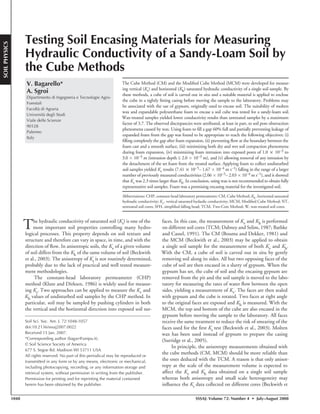
  • 3. 1050 SSSAJ: Volume 72: Number 4 • July–August 2008 Expandable polyurethane foam has been used with the excava- tion method to obtain soil bulk density data (Muller and Hamilton, 1992; Page-Dumroese et al., 1999; Brye et al., 2004) and with the hillslope infiltrometer to partially encase a soil block exposed in situ (Mendoza and Steenhuis, 2002). The foam is waterproof and it grows hard after 8 to 24 h of curing (Brye et al., 2004). Moreover, it is rela- tively easy to apply and to incise after hardening. Therefore, the foam seems to have the potential to encase in the field a soil volume usable in the laboratory for a two directional measurement of Ks. According to Muller and Hamilton (1992), soil particles remain attached to the cast when it is removed from the hole prepared for bulk density deter- mination. This may suggest that the contact between the foam and the soil should be assured but this hypothesis has to be specifically tested before considering the foam as being a suitable material for Ks measurement. According to Brye et al. (2004), expandable poly- urethane foam typically expands to several times the volume of foam initially injected and, therefore, it is usually recommended to fill a gap only 50% full to allow the foam to expand on its own to completely fill the gap without much excess to cut off and remove. However, the excavation method for bulk density determination has been applied by filling the cavity completely full and placing a cardboard plate with a weight across the surface to ensure a complete expansion of the foam into all microtopographic variations in the outer surface of the exca- vated cavity (Muller and Hamilton, 1992; Brye et al., 2004). Filling a cavity, such as the void space within a box placed around the soil cube (Bouma and Dekker, 1981), with a relatively small amount of foam may preclude complete covering of the exposed soil surfaces. Instead, using a large or a relatively large amount of foam may be important to improve both the rigidity of the casing and the contact between the casing and the treated soil surfaces. However, pressures may also develop at the interface between the foam and the soil dur- ing foam expansion. These pressures may have an adverse effect on the structural characteristics of the sampled soil volume and hence on the reliability of the measured Ks value. Expanding foam might also penetrate exposed pores. Therefore, it is necessary to improve our knowledge on both the soil compaction and pore occlusion phenom- ena induced by foam expansion to establish the possibility of using this material for the preparation of a soil casing. MATERIALS AND METHODS Field Site A flat area supporting a citrus orchard was used for this study at the Faculty of Agriculture of the Palermo University. The study was conducted on a soil (Typic Rhodoxeralf) having a relatively high sand (>50%) and gravel (13%) content. According to the USDA classification (Gee and Bauder, 1986), most textures of 12 replicated soil samples were sandy-loam. The experiments were performed in the period ranging from October 2004 to November 2006, collecting the soil samples immediately before conducting an experiment. The experimental site was not disturbed from 2002 until the experiments were completed. The original cube method was intended specifically for clay soils to avoid problems including puddling of the sidewalls and closure of the macropores due to drilling of auger holes, unrepresentativeness of Ks results obtained with small core samples, and changes in macrop- orosity due to pushing cylinders into the soil (Bouma and Dekker, 1981). For the soil considered in this investigation, sidewall smear- ing may affect the Ks values obtained with the Guelph permeame- ter method (Bagarello, 1997), and the size of the core influences the measured Ks by the CHP method (Bagarello and Provenzano, 1996). Moreover, soil structure alteration phenomena can occur due to push- ing a cylinder into the soil. Therefore, the cube methods are attractive to improve the reliability of the Ks data for this sandy-loam soil. Molten Wax The effect of molten wax on Ks measurement was evaluated by a comparison between the Ks results of wax-treated and untreated soil surfaces. Interpreting the results of a single comparison may be difficult because many factors influence the measured Ks values (e.g., Reynolds et al., 2000). Therefore, three different experiments were performed, varying soil collection and sample treatment procedures among the experiments, in an attempt to reduce the uncertainties in the interpretation of the Ks results. Experiment No. 1 The MCM and the TCM were compared to determine the anisotropy of Ks. Five spots of 1.0 m × 1.0 m were randomly selected within a 10-m2 area. The following soil samples were obtained at each spot after removing the upper layer, approximately 0.10 m thick: (i) a cubic sample with a side of 0. 13 m, encased in a casing of wax (Fig. 1a to 1c), and (ii) a vertically oriented and a horizontally oriented soil core, collected by using stainless steel cylinders (diameter = 0.085 m, height = 0.115 m) (Fig. 1d). The cubic sample was obtained by exposing in situ a 0.15-m-high soil volume. A square wooden box with a side of 0.17 m, open at two opposing ends, was placed around the exposed prism of soil before pouring the molten wax to encase the soil. The walls of the box were hinged to allow detachment of the sidewalls from the casing containing the soil cube (Bouma and Dekker, 1981). After the wax had set, the prism was detached and it was turned upside down. A layer of soil of 0.02 m was removed from the bottom end of the sample and molten wax was poured to com- pletely encase the soil sample. Before saturated hydraulic conductivity measurement, two opposing faces of the wax casing were removed by a heated knife. The exposed soil pores appeared to be, at least partially, soaked with wax. Therefore, a layer of approximately 0.01 m of soil was removed from both exposed faces. Then, Kv was determined. Two or 3 d later, the faces were resealed with wax and the cube was turned through 90°. Two other opposing faces were exposed and Kh was mea- sured after removing a layer of approximately 0.01 m of soil from both exposed faces. Each soil sample (both cubic and cylindrical) was placed on a nylon guard cloth and a wire net to support the weight of the soil before starting the Ks test. Experiment No. 2 Five spots of 1.0 m × 1.0 m were randomly selected within an area of approximately 10 m2 and stainless steel cylinders were used to collect two undisturbed soil cores (diameter = 0.085 m, height = 0.115 m) at each spot, after removing the upper 0.10 m of soil. For each spot, a randomly chosen soil core was treated with wax (W soil core). In particular, the soil core (maintained in the stainless steel cylinder) was placed on a polystyrene disc (diameter = 0.085 m, height = 0.02 m) and a PVC pipe 0.118-m-diameter × 0.15-m-high was placed around the core. Molten wax was poured into the PVC pipe, fully covering the soil core by wax. After that wax had set, the sample was turned upside down, the polystyrene disc was removed, and the exposed soil surface (bottom of the soil core) was covered by a 0.02-m-thick layer of molten wax. A few days after the treatment, the upper and lower faces of the wax were removed by a heated knife. A thin layer of soil (5.0 × 10⁻³ m) was also removed from both faces of the core by gently using a sharp knife,
  • 4. SSSAJ: Volume 72: Number 4 • July–August 2008 1051 notwithstanding that the soil surface did not appear to be soaked with wax in this experiment. The other soil core that was also used for the first experiment was not treated with wax (NT soil core). The Kv value of each W and NT soil core was measured. Experiment No. 3 Five spots of 1 m × 1 m were randomly selected within an area of approximately 15 m2. Both the CM and the MCM were applied to collect two dif- ferent soil samples at each spot, after removing the upper 0.03 m of soil. Each soil sample (0.13 × 0.13 × 0.15 m3) was carved out in situ by removing the soil along its sides. A square wooden box with a side of 0.17 m was placed around the soil prism and molten wax was poured into the space between the walls of the box and the exposed surfaces of the soil sample. For the soil samples collected with the MCM, both the upper and the lower face of the cube were also coated with wax. The upper and the bottom end of the soil sample collected with the CM were not sealed with wax. Instead, a piece of cardboard was placed on the upper face of the prism of soil to pre- serve the surface of the sample from contact with the molten wax used to prepare the casing. The Kv value of each collected soil sample was measured in the laboratory. The upper and lower faces of each MCM sample were exposed before measuring Kv, by using a heated knife. For this experiment, the soil surface did not appear to be soaked with wax and a layer of soil was not removed from the sample. For the CM samples, the already open faces (i.e., not treated with wax) were used to measure Kv. Experiments No. 1 through No. 3 For all experiments, an attempt to use mol- ten wax at a temperature as close to the solidifying temperature as possible was performed (Frasier and Keiser, 1993). The conductivity was measured in the laboratory by the CHP method (Fig. 1e) (Klute and Dirksen, 1986). The soil was not saturated before performing the Ks test because most natural and man-made infiltration processes result in significant air entrapment within the porous medium (Reynolds, 1993). In other words, the so-called field-saturated hydraulic conduc- tivity, or satiated conductivity, was considered in this investigation given that the lack of a complete filling of the pores between soil par- ticles in a satiated soil is caused by the entrapment of air as water enters the soil. In addition, it should be noted that the term field- saturated hydraulic conductivity has been used in the literature for other laboratory experiments (e.g., Odell et al., 1998). The constant thickness of the water layer above the surface varied between 0.014 and 0.020 m, depending on the soil sample. Drained water volumes were monitored for ≥ 6 h. Measurement of outflow started at the beginning of the experiment to detect occurrence of flow stabiliza- tion. The data corresponding to a stable outflow process were used to calculate Ks. For all experiments, the volumetric soil water content at the time of sampling, θi, was determined gravimetrically. The mean value of θi was equal to 0.190 m3m−3 (coefficient of variation, CV = 0.075, sample size, N = 10) for Exp. no.1, 0.193 m3 m−3 (CV = 0.284, N = 5) for Exp. 2, and 0.216 m3 m−3 (CV = 0.024, N = 5) for Exp. 3. According to Iovino (1998), in the sampled area, the soil water con- tent corresponding to the field capacity, FC (i.e., pressure head value, h = −0.033 MPa), and the permanent wilting point, PWP (i.e., h = -1.5 MPa), is equal to 0.256 m3 m−3 and 0.140 m3 m−3, respectively. Therefore, all experiments were performed in a soil having intermedi- ate water content between the FC and PWP water contents. Polyurethane Foam Different experiments were performed to evaluate contact of foam with a smooth surface, foam expansion, foam induced dry- and wet-soil compaction, and foam intrusion into exposed pores. An additional experiment was performed to test use of foam in the field. Mungo Swiss Quality (mungo, Italy, Padova, www.mungo.it) pres- surized cans of 750 mL, with a reported volume of 50 L of expanded foam, were used in this investigation1. Fig. 1. Field and laboratory application of the Modified Cube Method with wax and the Two-Core Method (TCM): a) soil prism encased in a casing of wax in the field; b) encased soil sample in the laboratory after removing the wooden box; c) exposed soil surface; d) collection of soil cores for the application of the TCM; e) application of the Constant-Head Permeameter method to a cubic soil sample. 1 Mention of a product does not constitute endorsement by the authors or the University of Palermo.
  • 5. 1052 SSSAJ: Volume 72: Number 4 • July–August 2008 Foam Contact and Expansion An experiment was performed to evaluate the ability of polyure- thane foam to provide a good contact with a smooth surface and to quantify foam expansion. A PVC cylinder (diameter = 0.094 m, height = 0.114 m) open at both ends was placed on a moist sheet of blotting paper and a small quantity of water was sprayed on the inner walls of the cylinder. A pre-established amount of foam was injected into the cylinder. Then, a moist sheet of blotting paper, a wooden tablet and a weight of 70–80 N were placed on the top of the cylinder. Different cylinders were filled with different volumes of foam, equal to 20, 40, 60, and 80% of the volume of the cylinder, respectively. Two PVC cylinders were filled with a given amount of foam to obtain two sets (set 1 and set 2) of filled cylinders. Two additional cylinders were filled 20% and 50% full, respectively, without placing any weight on the top (set 3). For all sets, the foam was left to cure for two or 3 d. The PVC cylinders of set 1 were cut by a heated knife and removed, leav- ing a mold of foam that was examined visually. Cylinders of sets 2 and 3 were used to test occurrence of edge flow phenomena. Expanded foam was removed from the top of the cylinder to leave a 0.03-m-high space that was maintained partially filled by water (water layer thick- ness = 0.025 m) for at least 3 d. A funnel and a small container were placed below each cylinder to collect percolated water. For each cylin- der used in the investigation, the volume of the expanded polyurethane foam was also determined by volume displacement of water in a large glass container (Muller and Hamilton, 1992). Foam Induced Soil Compaction An experiment was performed using air-dried soil passing a 2.0 × 10⁻³ m sieve and packed into 15 Plexiglas tubes (i.d. = 0.094 m, height = 0.5 m). A nylon guard cloth and a wire net were connected to the base of the tube to support the weight of the soil. The soil in the tubes was compacted manually and small amounts of soil were added during compaction to obtain a final height of the soil sample of exactly 0.5 m, as described by Bagarello et al. (2006). For each tube, the dry bulk density, ρb, the initial volumetric soil water con- tent, θi, and the volumetric saturated soil water content were deduced (Bagarello et al., 2004, 2006). A PVC disk of 0.15 mm thickness and 94 mm diameter was placed on top of the soil sample. A Plexiglas tube (i.d. = 0.094 m, height = 0.150 m), covered internally with plastic wrap, was firmly connected to the top of the soil column tube. The interior tube and top PVC surfaces were spray-moistened just before foam was injected to fill a pre-established fraction of the volume above the soil sample. Then, a rectangular wooden tablet was secured tightly to the top of the short tube using iron wire (Fig. 2, right). By this procedure, the foam-induced pressure on the soil surface was maximized. For six ran- dom samples, 30% of the volume above the soil surface was initially filled by foam (03AV samples). For another six random samples, 60% of the volume was filled (06AV samples). Three samples were left uncovered (00AV samples). The cured foam was later removed and its length was measured. The Kv value of each soil sample was measured by the transient simplified falling head (SFH) technique (Bagarello et al., 2004, 2006). Before applying SFH, a 0.01 m layer of soil was gently scraped off the top for three 03AV samples and three 06AV samples. These samples are denoted by adding ‘-S’ (03AV-S and 06AV-S). For the remaining nine samples, the soil surface was not altered. These samples retained the notation 03AV and 06AV. An estimate of α* = 12 m−1 (Elrick and Reynolds, 1992) was used to calculate Kv. Wet soil conditions at the time of the Ks measurement and some foam leakage from the confined space during foam expansion may be anticipated in field use of the method. Therefore, another experi- ment was conducted to represent these conditions. Soil from the first compaction experiment (described above) was reused. It was air dried, passed again through a 2-mm sieve, and packed into 12 columns. The columns were saturated from the top and then allowed to freely drain for 3 d. Their water content was determined gravimetrically, PVC disks were again placed on the soil surface, and Plexiglas tubes attached (Fig. 2, left). Elastic bands were used (rather than wire) to hold down the wood tablet and allow limited foam expansion. For six random samples, foam was injected until 60% of the available volume was filled. The other six samples were left uncovered. Cured foam was removed. Again, 0.01 m of soil was scraped off the top for three uncovered columns (00AV-W-S) and three foam-treated col- umns (06AV-W-S). A hairdryer was used briefly to dry the exposed soil before removing it. The soil surface of the other samples (00AV-W and 06AV-W) was neither scraped nor dried. The SFH technique was used to measure Kv for all these samples. Foam Intrusion into Exposed Pores The experimental procedure was similar to that used for the dry soil (first) foam induced soil compaction experiment. In this case, however, the soil in the tube was gently wetted to a depth of approxi- mately 0.06 to 0.07 m and some vertical pores (six with a diameter of 1.0 × 10⁻³ m, four of 2.0 × 10⁻³ m and four of 3.0 × 10⁻³ m) were drilled into the exposed soil surface to a depth of 0.05 m, 24 h after wetting. Then, foam was injected directly on the soil surface, in the space confined by the short Plexiglas tube, until 60% of the available volume was filled. As described above, foam expansion outside the confined space after injection was totally prevented (wire) for three samples and partially prevented (elastic bands) for the other three samples. The foam plug was removed after >24 h of curing and both the soil surface and the bottom of the plug were examined. Using Foam in the Field Foam was used to encase soil prisms within an area of 10 m2. A few centimeters of soil were removed from the surface and a soil prism (0.11 × 0.11 × 0.14 m3) was carved out (Fig. 3a). A wooden box (side length = 0.17 m), its inner walls covered by plastic wrap to avoid foam adhesion, was placed around the exposed soil prism. Water was Fig. 2. Plexiglas tubes with the wooden tablet connected to the top of the short tube by using elastic bands (left, foam leakage dur- ing expansion partially prevented) and iron wire (right, foam leakage during expansion totally prevented).
  • 6. SSSAJ: Volume 72: Number 4 • July–August 2008 1053 sprayed on the inner walls of the box and foam was injected to fill 60 to 70% of the space between the box and the soil (Fig. 3b). Wood and a weight of not more than 40 to 50 N were then used to confine foam expansion (Fig. 3c). The cured cast with enclosed soil was detached and turned upside down. A layer of soil 0.03-m thick was removed from the bottom, which was then also encased in foam confined by wood and a weight. Soil cores (0.05 m diam. by 0.05 m long) were also collected to determine θi (0.134 m3m−3, CV = 0.064, N = 6). In the laboratory, the cube was taken from the wooden box and the foam was removed from both the top and bottom faces using a box cutter. A nylon guard cloth and a wire net supported the weight of the soil (Fig. 3d). The cube was then placed in the apparatus to measure Kv (Fig. 1e), using 0.015 m ponded water depth. Calculation of Kv was based on the ultimate steady discharge rate. The cube was allowed to drain under gravity for 3 d. The exposed faces were resealed with foam, the cube turned through 90°, two more faces exposed, and Kh determined (Beckwith et al., 2003). Summary and Statistical Analysis of Data The statistical distribution of the Ks data was not checked in this investigation due to the limited sample size for a particular data set. However, the Ks results of the undisturbed soil samples were assumed to be log-normally distributed since the statistical distribution of these data is generally log-normal (Lee et al., 1985; Warrick, 1998). The geometric mean and the associated CV were calculated to summarize the Ks values of undisturbed soil (Lee et al., 1985). The Ks results of the repacked soil samples were assumed to be normally distrib- uted since unstructured soil was used, and the arithmetic mean and the associated CV were used to summarize a given data set. Previous investigations performed in the same experimental area with larger sample sizes supported the choice of using a log-normal distribution for the undisturbed soil results and a normal distribution for the repacked samples (Bagarello and Provenzano, 1996; Bagarello et al., 2000, 2004, 2006). Statistical comparison between means was con- ducted using two-tailed t tests. The natural logs of the data were used for the undisturbed soil sample results. A probability level, P = 0.05, was used for all statistical comparisons. RESULTS AND DISCUSSION Molten Wax In the Exp.1, the ratio between the mean values of Kv and Kh was equal to 0.8 for the MCM treatment and to 1.1 for the TCM treatment (Table 1). In both cases, these differences were not statistically significant. Therefore, both treatments suggested Fig. 3. Application of the Modified Cube Method with foam: (a) exposing the soil prism in the field; (b) filling part of the space between the wooden box and the exposed soil volume with foam; (c) partially preventing foam leakage during expansion; and (d) placing a nylon guard cloth and a wire net at the bottom of the cube to support the weight of the soil.
  • 7. 1054 SSSAJ: Volume 72: Number 4 • July–August 2008 that the anisotropy of Ks was not substantial given that relatively low differences between Kv and Kh values were detected (e.g., Dabney and Selim, 1987). However, the MCM yielded lower and more variable Kv and Kh results than the TCM. In particu- lar, the two methods differed by a statistically significant factor of 3.7 in the vertical direction and of 2.7 in the horizontal one. In the Exp. no.2, the W soil cores yielded slightly lower (i.e., by 25%) and more variable results than the NT cores (Table 1). However, the discrepancy between the two mean values of Kv was not statistically significant. In the Exp. 3, the MCM treat- ment yielded significantly lower (by a factor of 2.0) and more variable Kv results than the CM treatment (Table 1). Two salient points of a comparison between Ks measure- ment methods or procedures are (i) establishing the impor- tance of the detected differences and (ii) identifying the factors determining these differences. With reference to the first point, a common approach consists of evaluating the statistical sig- nificance of the differences between two treatments. However, the amount of the difference may be of interest, with statistical significance being of secondary importance (Webster, 2001). A change in the value of Ks by a factor of two or three is not particularly important given that Ks varies in nature by several orders of magnitude (from 1.0 × 10⁻⁹ m s−1 for tight clays to 1.0 × 10⁻⁴ m s−1 for coarse sands) and given the extreme spatial variability of Ks (often CVs of several hundred percent) (Elrick and Reynolds, 1992; Elrick et al., 2002). For three of the four comparisons performed in this investigation, the discrepancy between two sets of data was close to or slightly larger than a factor of two or three, and also statistically significant, sug- gesting that the differences between the mean Ks values were moderate (i.e., differences were detected, but they were not substantial) in most cases. With reference to the second point, the observed discrep- ancies within an experiment may depend on different factors, including occurrence of more appreciable edge flow phe- nomena in the untreated soil samples (Exp.1 and 2) or spa- tial variability of Ks (i.e., the untreated soil samples were really more permeable than the samples treated with wax). However, the fact that, for all experiments, the sign of the differences between two data sets was the one expected as a consequence of obstruction phenomena of the exposed soil pores (i.e., Ks of a treated surface < Ks of an untreated surface) suggested that these last phenomena were at least a concomitant cause of the obtained results. Support to this interpretation was given by previous investigations show- ing wax penetration into exposed pores (Dexter, 1976; Hoag and Price, 1997). The proposed interpretation is that removing the upper layer of soil before measuring the con- ductivity of a wax-treated sample was not effective in elimi- nating any pore obstruction when exposed pores appeared to be soaked with wax. Therefore, this investigation suggested that, generally, molten wax had a moderately adverse effect on the measured Ks values. It would be prudent not to use wax for preparing a soil sample casing, at least with the same application pro- cedure used in this investigation. An alternative procedure could presuppose an initial application of several thin layers of molten wax on the exposed soil surfaces by a brush, before pouring the wax in the space between the soil sample and the box. A similar procedure was applied by Park and Smucker (2005) in an investigation on the Ks of macroaggregates of soil. However, the ability of this more complicated procedure to avoid wax intrusion into exposed pores is untested. Polyurethane Foam Foam Contact and Expansion In the PVC cylinders initially filled 20% full, foam expanded to fill almost all the cylinder volume. In the other cases (initial filling volume ≥ 40%), appreciable foam poured out of the cylinder, notwithstanding that a weight was placed on the top. In all cases, the lateral surface of the foam mold was found to be reasonably smooth (i.e., with a few localized and small depressions), suggesting that the contact between the foam and the PVC cylinder was satisfactory. Moreover, water did not appear at the bottom end of the cylinders, suggesting that the contact was tight enough to prevent edge flow phenom- ena in all cases. This result was viewed as an encouragement to the field use of foam as a soil encasing material. The reasoning was that a good contact with a smooth surface may be indica- tive of a good contact with a surface showing some irregularity, as the soil surface, because the material has the ability to closely adhere to any irregularities (Muller and Hamilton, 1992; Brye et al., 2004). However, leakage between the foam and the soil was not specifically tested in this investigation. The reason was that theoretically suitable methodologies for investigating this phenomenon may yield uncertain results. For example, leakage between the foam and the soil could be tested by encasing a core in foam and measuring flow rate from different concen- tric circular area at the base of the core (Hill and King, 1982; Cameron et al., 1990). However, differences between Ks values of different portions of the soil core may also be due to small scale variability phenomena, especially in a macroporous soil as the investigated one. The ratio, RF, of expanded foam volume to injected foam varied between 3.0 and 5.7 (mean = 4.4, CV = 0.19, N = 10). Table 1. Sample size, N, minimum, Min, maximum, Max, geometric mean, M, and coefficient of variation, CV, of the vertical, Kv, and horizon- tal, Kh, saturated soil hydraulic conductivity values obtained in the experiment i) no.1, by the Modified Cube Method (MCM) with wax and the Two-Core Method (TCM), ii) no.2, by using wax-treated (W) and untreated (NT) soil cores, and iii) no.3, by using the Cube Method (CM) and the MCM with wax for collecting soil samples in the field. Variable Treatment N Min Max M† CV m s−1 m s−1 m s−1 Experiment no.1 Kv MCM 5 9.25x10⁻⁶ 4.71x10⁻⁵ 2.74x10⁻⁵ a(c) 0.738 TCM 5 6.88x10⁻⁵ 1.14x10⁻⁴ 1.01x10⁻⁴ b(c) 0.219 Kh MCM 5 1.36x10⁻⁵ 4.93x10⁻⁵ 3.39x10⁻⁵ a(d) 0.568 TCM 5 6.35x10⁻⁵ 1.21x10⁻⁴ 9.05x10⁻⁵ b(d) 0.306 Experiment no.2 Kv W 5 4.91x10⁻⁵ 1.05x10⁻⁴ 7.63x10⁻⁵ e 0.302 NT 5 6.88x10⁻⁵ 1.14x10⁻⁴ 1.01x10⁻⁴ e 0.219 Experiment no.3 Kv CM 5 2.01x10⁻⁵ 5.41x10⁻⁵ 3.58x10⁻⁵ (f) 0.388 MCM 5 7.42x10⁻⁶ 3.36x10⁻⁵ 1.78x10⁻⁵ (f) 0.610 † A statistical comparison was made between those values followed by the same letter. Means followed by the same letter enclosed in parentheses are significantly different (P = 0.05); means followed by the same letter, but not enclosed in parentheses, are not significantly different.
  • 8. SSSAJ: Volume 72: Number 4 • July–August 2008 1055 This ratio was not correlated with the proportion of the cyl- inder volume initially filled (coefficient of determination, r2 = 0.05) and the correlation was even lower without data from the cylinders left open after filling (r2 = 0.02, N = 8). According to these results, slightly more than one third of the void space should be initially filled with foam to obtain a cast. Foam Induced Soil Compaction Bulk density and initial soil water content values for ini- tially dry soil samples were all nearly identical (Table 2). As expected, foam remained confined within the short Plexiglas tube in all cases. For some 03AV samples, foam expansion was not enough to fill completely the confined volume. No void space remained in the short tube of the 06AV samples. The PVC disk on the soil surface simplified removal of the foam plug. In all cases, the foam plug was <1.0 × 10⁻³ m longer than the expected length (0.15 m), suggesting that soil compaction of this dry soil (Table 2) was negligible. For a given filling volume (30 or 60%), the mean value of Kv obtained after scraping away the upper soil layer was not statistically different from the one obtained without removing the soil from the upper part of the sample (Table 2). Moreover, the comparison of the Kv results of the 00AV samples with the other four groups of data (03AV, 03AV-S, 06AV, and 06AV-S) did not show any statistically significant difference. Therefore, using foam to prepare a plug did not affect the measurement of Kv, notwithstanding that expansion of the foam was totally confined within a relatively small space. According to this experiment, however, initially filling one third of a cavity with foam was not enough for complete fill- ing. Filling the cavity 60% full resulted in a complete fill with expanded foam. The usual recommendation to be sure the foam expands to completely fill a gap without much excess to cut off and remove is 50% initial filling. The global mean of the 15 Kv results was equal to 8.92 × 10⁻⁶ m s−1. This value was lower than the one (3.44 × 10⁻⁵ m s−1) obtained by Bagarello et al. (2006) by using exactly the same soil and the same measurement procedure (i.e., SFH technique). The reason of this discrepancy was that the soil used by Bagarello et al. (2006) was less compacted (mean ρb = 1109 kg m−3 versus mean ρb = 1221 kg m−3 in this study). In other words, the measured conductivity values were consistent with the bulk densities of the repacked soil samples. Samples with very uniform ρb and θi values also resulted for the experiment with the initially wet soil (Table 3). Only the difference between the ρb values of the 00AV-W samples and the 06AV-W-S samples was statistically significant but very small (0.6%). The comparison between the Kv results of the four groups of samples (00AV-W, 00AV-W-S, 06AV-W, and 06AV-W-S) did not show any statistically significant differ- ence (Table 3). Therefore, using foam to prepare a plug did not affect the measurement of Kv of the initially wet soil when foam leakage was partially prevented. The global mean of the 12 Kv results, equal to 9.72 × 10⁻⁷ m s−1, was appreciably lower than the one obtained with the initially dry soil. A similar level of discrepancy between initially dry and wet conditions was detetcted by Bagarello et al. (2006) with a repacked loam soil. According to these authors, wetting the soil sample promoted closure or narrowing of the largest pores. Probably, another concomitant cause was that the experiment with the initially wet soil was performed on soil samples that were slightly denser (mean ρb = 1252 kg m−3) than the ones used for the exper- iment with the initially dry soil (mean ρb = 1221 kg m−3). However, the density change was very small, suggesting that it was a minor factor affecting the observed discrepancies. Other possible explanations of the differences between wet and dry Kv Table 2. Mean and coefficient of variation, in parentheses, of the dry bulk density, ρb, initial volumetric soil water content, θi, and vertical saturated soil hydraulic conductivity, Kv, values mea- sured on different types of initially dry repacked soil samples. ρb† θi Kv kg m−3 m3 m−3 m s−1 00AV samples‡ 1224 (0.007) abcd 0.049 (0.007) 9.39x10⁻⁶ (0.158) abcd 03AV samples 1223 (0.005) ae 0.049 (0.005) 8.44x10⁻⁶ (0.022) ae 03AV-S samples 1216 (0.005) be 0.049 (0.005) 8.58x10⁻⁶ (0.076) be 06AV samples 1224 (0.008) cf 0.049 (0.008) 9.44x10⁻⁶ (0.068) cf 06AV-S samples 1218 (0.007) df 0.049 (0.007) 8.78x10⁻⁶ (0.072) df † For a given variable, a statistical comparison was made between those mean values followed by the same letter. Means followed by the same letter enclosed in parentheses are significantly different (P = 0.05); means followed by the same letter, but not enclosed in parentheses, are not significantly different. ‡ 00AV: no addition of foam above the soil surface; 03AV: 30% of the available volume filled with foam; 03AV-S: 30% of the available volume filled with foam, 0.01 m of soil scraped away before measuring Kv; 06AV: 60% of the available volume filled with foam; 06AV-S: 60% of the available volume filled with foam, 0.01 m of soil scraped away before measuring Kv. Sample size N = 3 for each type of soil sample. Table 3. Mean and coefficient of variation, in parentheses, of the dry bulk density, ρb, initial volumetric soil water content, θi, and vertical saturated soil hydraulic conductivity, Kv, values mea- sured on different types of initially wet repacked soil samples. ρb† θi Kv kg m−3 m3 m−3 m s−1 00AV-W samples‡ 1247 (0.002) ab(c) 0.443 (0.017) abc 8.89x10⁻⁷ (0.194) abc 00AV-W-S samples 1249 (0.003) ade 0.441 (0.017) ade 9.72x10⁻⁷ (0.196) ade 06AV-W samples 1257 (0.008) bdf 0.431 (0.003) bdf 8.89x10⁻⁷ (0.330) bdf 06AV-W-S samples 1255 (0.002) (c)ef 0.439 (0.014) cef 1.08x10⁻⁶ (0.243) cef † For a given variable, a statistical comparison was made between those mean values followed by the same letter. Means followed by the same letter enclosed in parentheses are significantly dif- ferent (P = 0.05); means followed by the same letter, but not enclosed in parentheses, are not significantly different. ‡ 00AV-W: no addition of foam above the soil surface; 00AV-W-S: no addition of foam above the soil surface, 0.01 m of soil scraped away before measuring Kv; 06AV-W: 60% of the available vol- ume filled with foam; 06AV-W-S: 60% of the available volume filled with foam, 0.01 m of soil scraped away before measuring Kv. Sample size N = 3 for each type of soil sample.
  • 9. 1056 SSSAJ: Volume 72: Number 4 • July–August 2008 could be the perturbation of the material and the choice of the α* value for the SFH calculations. Foam Intrusion into Exposed Pores Two types of results were obtained, depending on the level of impediment (total or partial) to foam expansion outside the confined space. In the first case (totally prevented foam expansion), foam penetrated exposed pores to a depth varying with the diameter of the pore (Fig. 4a). In particular, the depth of the foam cast varied between a maximum of 0.01 m for the largest pores (diameter = 3.0 × 10⁻³ m) to a minimum of <1.0 × 10⁻³ m for the smallest pores (1.0 × 10⁻³ m). In a few cases, the intrusion broke during extraction due to its small diameter. The small pieces of foam remaining in the soil were clearly visible and easily removable. The bottom of the plug had a dome shape, with a maximum swelling of 6.0 × 10⁻³ m, suggesting some compaction during foam expansion. For the soil samples with a partially prevented foam expansion, foam penetration into exposed pores was much less pronounced (depth of the intrusion ≤ 2.0 × 10⁻³ m) and not clearly dependent on the size of the exposed pore (Fig. 4b). No pieces broke off. The bottom of the plug was flat, suggesting that soil compaction did not occur in this case. According to this investigation, wet soil compaction and foam intrusion into exposed pores were negligible when foam expansion was partially prevented. Preventing any expansion determined some compaction of wet soil. Foam intrusion into exposed pores was more appreciable but any intrusion was easily removed. These results were encouraging for using the foam as an encasing material since only a partial impediment to foam expansion may be expected in the field. Using Foam in the Field Sample collection in the field and Kv and Kh measurement in the labo- ratory were easily accomplished sug- gesting foam would be an appropriate encasing material. Moreover, no evi- dence of foam intrusion into the soil pores was observed. For all samples, Kv was greater than Kh with Kv/Kh ratios ranging between 1.9 and 3.6. The mean value of Kv was 2.3 times greater than the mean Kh result and the differ- ences between the two sets of data were statistically significant (Table 4). All Kv values were in the range of the vertical Ks results (2.06 × 10⁻⁵– 2.03 × 10⁻⁴ m s−1, N = 11) obtained by Bagarello and Sgroi (2007) by applying in the same area the SFH technique (Bagarello et al., 2004) with sampled soil volumes (diameter of the cylinder = 0.14 or 0.15 m, depending on the cylinder, depth of insertion = 0.12 m) and soil moisture conditions (mean θi = 0.116 m3 m−3) relatively similar to the ones of this investigation. Highly variable differences between Kv and Kh were detected both in peats (Chason and Siegel, 1986; Schlotzhauer and Price, 1999; Beckwith et al., 2003; Surridge et al., 2005) and in mineral soils (Bouma and Dekker, 1981; Dabney and Selim, 1987; Bathke and Cassel, 1991; Caris and Van Asch, 1991). In particular, 0.5 ≤ Kv/Kh ≤ 46000 was obtained by Bouma and Dekker (1981) in four clay soils. The Kv/Kh ratio of other clayey soils varied between 0.0003 and 114 (Bathke and Cassel, 1991). Values of Kv/Kh equal to 0.06 and 42 were obtained by Caris and Van Asch (1991) in another clayey soil. For a silt-loam soil, measured conductivities were three times greater in vertical than in horizontal direction within the Btx1 horizon whereas differences between the two directions were not detected within the Ap horizon (Dabney and Selim, 1987). Possible factors determining Kv > Kh for this sandy-loam soil might include the presence of near-vertical macropores and differences in the initial soil water content. Also, possibly the measurement of Kv and Kh on the same soil volume promoted soil structure modification affecting the Ks results. No matter how, the Ks anisotropy of this soil was appreciably lower than has been found in clayey soils. CONCLUSIONS Use of molten wax with the CM or MCM is not suggested for soil with relatively high sand and gravel content. This soil exposed to wax resulted in lower Ks values in three different tests. The discrepancy ranged from 25% (NS) to a factor of 3.7 (statistically significant). Pore obstruction caused by the molten wax is the probable cause. Further investigation of wax applica- tion procedures, in addition to those of this study and on low permeability soils, should be conducted to more exhaustively test the suitability of molten wax as a soil encasing material. Expandable polyurethane foam seemed to be a suitable encasing material for use with this coarse soil to measure anisot- ropy of Ks with the cube technique. Filling the cube gap volume about 60% with the foam before it expanded was successful. In Fig. 4. Foam intrusion into the exposed soil pores for the case of (a) totally prevented foam expan- sion, and b) partially prevented foam expansion. Table 4. Sample size, N, minimum, Min, maximum, Max, geometric mean, M, and coefficient of variation, CV, of the vertical, Kv, and horizontal, Kh, saturated soil hydraulic conductivity values obtained by collecting undisturbed soil samples with foam. Variable N Min Max M† CV m s−1 m s−1 m s−1 Kv 6 7.41x10⁻⁵ 1.67x10⁻⁴ 1.09x10⁻⁴ a 0.283 Kh 6 3.93x10⁻⁵ 6.02x10⁻⁵ 4.80x10⁻⁵ b 0.153 † Means followed by the same lowercase letter are not significantly different according to a two-tailed, t test (P = 0.05).
  • 10. SSSAJ: Volume 72: Number 4 • July–August 2008 1057 associated experiments, foam was found to prevent edge flow and to not appreciably compact initially dry soil. Compaction of initially wet soil was negligible when some leakage of the foam from the confined space occurred during the expansion stage. Further testing of foam with different soils, particularly those with a low compressive strength, and initial soil water condi- tions is desirable. There does remain some concern that foam expanding in a confined volume with low compressive strength soil could result in compaction. Field comparisons of expand- able foam, molten wax, and gypsum as encasing materials may give additional guidance for the most appropriate material to use for various soils and environmental conditions. ACKNOWLEDGMENTS We thank A.J. Baird and V. Comegna for the profitable discussions and the generous suggestions on the issues of Ks measurement by the cube methods. REFERENCES Bagarello, V. 1997. Influence of well preparation on field saturated hydraulic conductivity measured with the Guelph Permeameter. Geoderma 80:169–180. Bagarello, V., and G. Provenzano. 1996. Factors affecting field and laboratory measurement of saturated hydraulic conductivity. Trans. ASAE 39:153–159. Bagarello, V., and A. Sgroi. 2007. Using the simplified falling head technique to detect temporal changes in field-saturated hydraulic conductivity at the surface of a sandy loam soil. Soil Tillage Res. 94:283–294. Bagarello,V.,M.Iovino,andG.Tusa.2000.Factorsaffectingmeasurementofthenear saturated soil hydraulic conductivity. Soil Sci. Soc. Am. J. 64:1203–1210. Bagarello, V., M. Iovino, and D. Elrick. 2004. A simplified falling-head technique for rapid determination of field-saturated hydraulic conductivity. Soil Sci. Soc. Am. J. 68:66–73. Bagarello,V.,G.Giordano,andA.Sgroi.2005.Approfondimentisulcubemethod per la misura della conducibilità idraulica del suolo. Atti del Convegno Nazionale AIIA 2005 “L’Ingegneria agraria per lo sviluppo sostenibile dell’area mediterranea”, 27–30 Giugno, codice lavoro 6003 (In Italian.). Bagarello, V., D.E. Elrick, M. Iovino, and A. Sgroi. 2006. A laboratory analysis of falling head infiltration procedures for estimating the hydraulic conductivity of soils. Geoderma 135:322–334. Bathke, G.R., and D.K. Cassel. 1991. Anisotropic variation of profile characteristics and saturated hydraulic conductivity in an Ultisol landscape. Soil Sci. Soc. Am. J. 55:333–339. Beckwith, C.W., A.J. Baird, and A.L. Heathwaite. 2003. Anisotropy and depth-related heterogeneity of hydraulic conductivity in a bog peat. I: Laboratory measurements. Hydrol. Process. 17:89–101. Bouma,J.,andL.W.Dekker.1981.Amethodformeasuringtheverticalandhorizontal Ksat of clay soils with macropores. Soil Sci. Soc. Am. J. 45:662–663. Bouma,J.,L.W.Dekker,andH.L.Verlinden.1976.Drainageandverticalhydraulic conductivity of some Dutch “knik” clay soils. Agric. Water Manage. 1:67–78. Brye, K.R., T.L. Morris, D.M. Miller, S.J. Formica, and M.A. Van Eps. 2004. Estimating bulk density in vertically exposed stoney alluvium using a modified excavation method. J. Environ. Qual. 33:1937–1942. Cameron, K.C., D.F. Harrison, N.P. Smith, and C.D.A. McLay. 1990. A method to prevent edge-flow in undisturbed soil cores and lysimeters. Aust. J. Soil Res. 28:879–886. Caris,J.P.T.,andTh.W.J.VanAsch.1991.Geophysical,geotechnicalandhydrological investigations of a small landslide in the French Alps. Eng. Geol. 31:249–276. Chason, D.B., and D.I. Siegel. 1986. Hydraulic conductivity and related physical properties of peat, Lost River Peatland, northern Minnesota. Soil Sci. 142:91–99. Dabney, S.M., and H.M. Selim. 1987. Anisotropy of a fragipan soil: Vertical vs. horizontal hydraulic conductivity. Soil Sci. Soc. Am. J. 51:3–6. Dexter, A.R. 1976. Internal structure of tilled soil. J. Soil Sci. 27:267–278. Elrick, D.E., and W.D. Reynolds. 1992. Methods for analyzing constant-head well permeameter data. Soil Sci. Soc. Am. J. 56:320–323. Elrick, D.E., R. Angulo-Jaramillo, D.J. Fallow, W.D. Reynolds, and G.W. Parkin. 2002. Infiltration under constant head and falling head conditions. p. 47–53. InEnvironmentalmechanics:Water,massandenergytransferinthebiosphere. Geophysical Monogr. 129, American Geophysical Union, Washington, DC. Frasier, G.W., and J. Keiser. 1993. Thin layer measurement of soil bulk density. J. Range Manage. 46:91–93. Gee, G.W., and J.W. Bauder. 1986. Particle-size analysis. p. 383–411. In A. Klute (ed.) Methods of soil analysis. Part 1. 2nd ed. ASA and SSSA, Madison, WI. Hill, R.L., and L.D. King. 1982. A permeameter which eliminates boundary flow errors in saturated hydraulic conductivity measurements. Soil Sci. Soc. Am. J. 46:877–880. Hoag, R.S., and J.S. Price. 1997. The effects of matrix diffusion on solute transport and retardation in undisturbed peat in laboratory columns. J. Contam. Hydrol. 28:193–205. Iovino, M. 1998. Applicazione della tecnica Multistep Outflow per la determinazione delle proprietà idrauliche del terreno col metodo inverso. (In Italian.) Irrigazione e Drenaggio 4:25–34. Klute, A., and C. Dirksen. 1986. Hydraulic conductivity and diffusivity: Laboratory methods. p. 687–734. In A. Klute (ed.) Methods of Soil Analysis, Part 1. 2nd ed. Agron. Monogr. 9. ASA and SSSA, Madison, WI. Lee,D.M.,W.D.Reynolds,D.E.Elrick,andB.E.Clothier.1985.Acomparison of three field methods for measuring saturated hydraulic conductivity. Can. J. Soil Sci. 65:563–573. Mendoza, G., and T.S. Steenhuis. 2002. Determination of hydraulic behavior of hillsides with a hillslope infiltrometer. Soil Sci. Soc. Am. J. 66:1501–1504. Muller, R.N., and M.E. Hamilton. 1992. A simple, effective method for determining the bulk density of stony soils. Commun. Soil Sci. Plant Anal. 23:313–319. Odell, B.P., P.H. Groenevelt, and D.E. Elrick. 1998. Rapid determination of hydraulic conductivity in clay liners by early-time analysis. Soil Sci. Soc. Am. J. 62:56–62. Page-Dumroese, D.S., M.F. Jurgensen, R.E. Brown, and G.D. Mroz. 1999. Comparison of methods for determining bulk densities of rocky forest soils. Soil Sci. Soc. Am. J. 63:379–383. Park, E.J., and A.J.M. Smucker. 2005. Saturated hydraulic conductivity and porosity within macroaggregates modified by tillage. Soil Sci. Soc. Am. J. 69:38–45. Reynolds, W.D. 1993. Saturated hydraulic conductivity: Field measurement. In M.R. Carter (ed.) Soil sampling and methods of analysis. Can. Soc. of Soil Sci., Lewis Publishers, Boca Raton, FL. Reynolds, W.D., B.T. Bowman, R.R. Brunke, C.F. Drury, and C.S. Tan. 2000. Comparison of tension infiltrometer, pressure infiltrometer, and soil core estimates of saturated hydraulic conductivity. Soil Sci. Soc. Am. J. 64:478–484. Schlotzhauer, S.M., and J.S. Price. 1999. Soil water flow dynamics in a managed cutover peat field, Quebec: Field and laboratory investigations. Water Resour. Res. 35:3675–3683. Surridge, B.W.J., A.J. Baird, and A.L. Heathwaite. 2005. Evaluating the quality of hydraulic conductivity estimates from piezometer slug tests in peat. Hydrol. Proc. 19:1227–1244. Topp,G.C.,Y.T.Galganov,B.C.Ball,andM.R.Carter.1993.Soilwaterdesorption curves. p. 569–579. In M.R. Carter (ed.) Soil sampling and methods of analysis. Can. Soc. of Soil Sci., Lewis Publishers, Boca Raton, FL. Warrick, A.W. 1998. Spatial variability. p. 655–675. In D. Hillel (ed.) Environmental soil physics. Academic Press, San Diego, CA. Webster, R. 2001. Statistics to support soil research and their presentation. Eur. J. Soil Sci. 52:331–340. Zobeck, T.M., N.R. Fausey, and N.S. Al-Hamdan. 1985. Effect of sample cross-sectional area on saturated hydraulic conductivity in two structured clay soils. Trans. ASAE 28:791–794.