Downloaded 1,085 times
![Statement Format
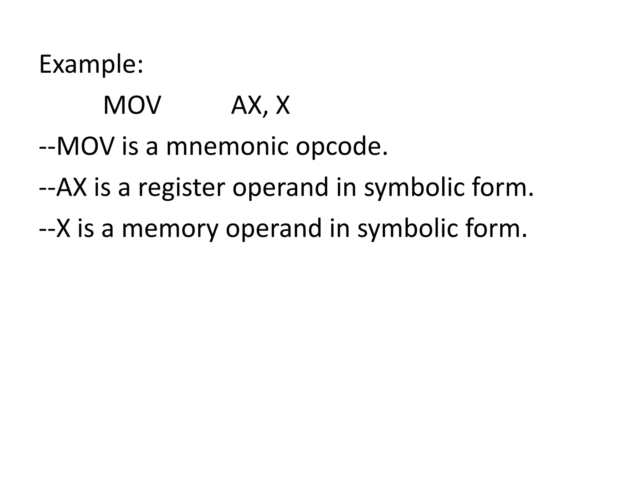
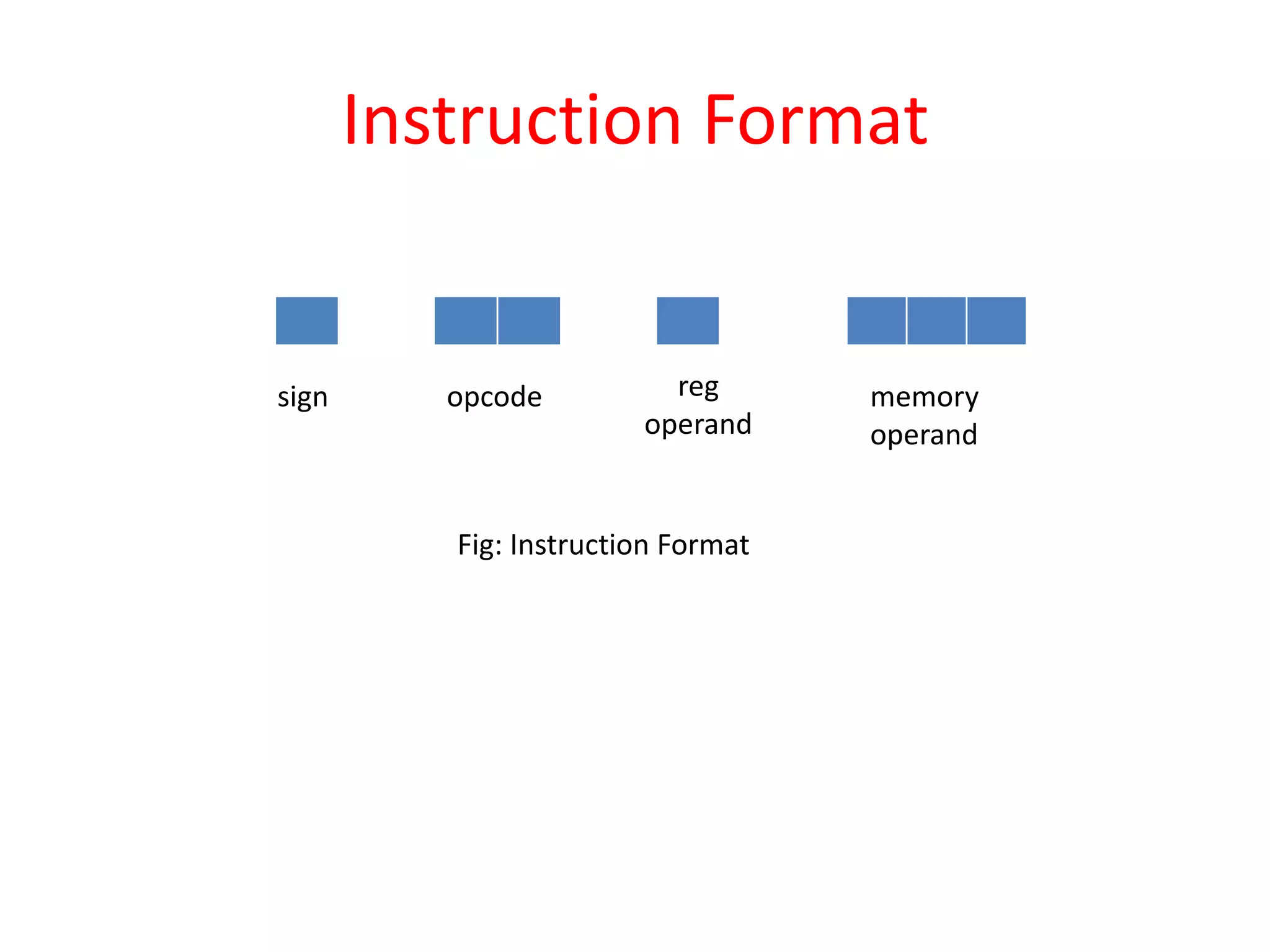
[Label] <Opcode> <operand Spec> [<operand spec>….]
1. Label:- Is optional.
2. Opcode:- Symbolic opcode
3. Operand:- Symbolic name (Register or Memory
variable)](https://image.slidesharecdn.com/assemblers-140416005114-phpapp02/75/Assemblers-6-2048.jpg)
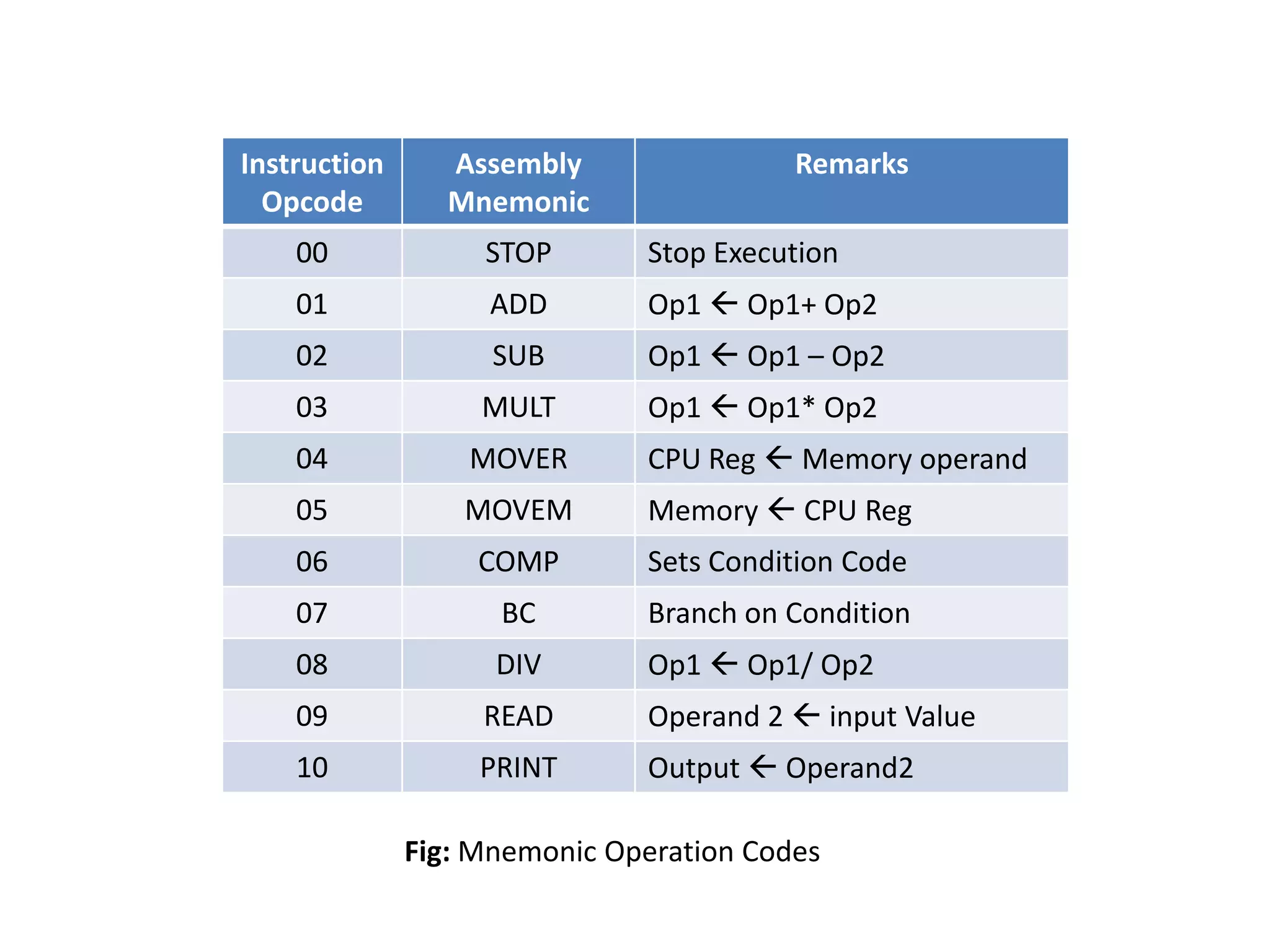
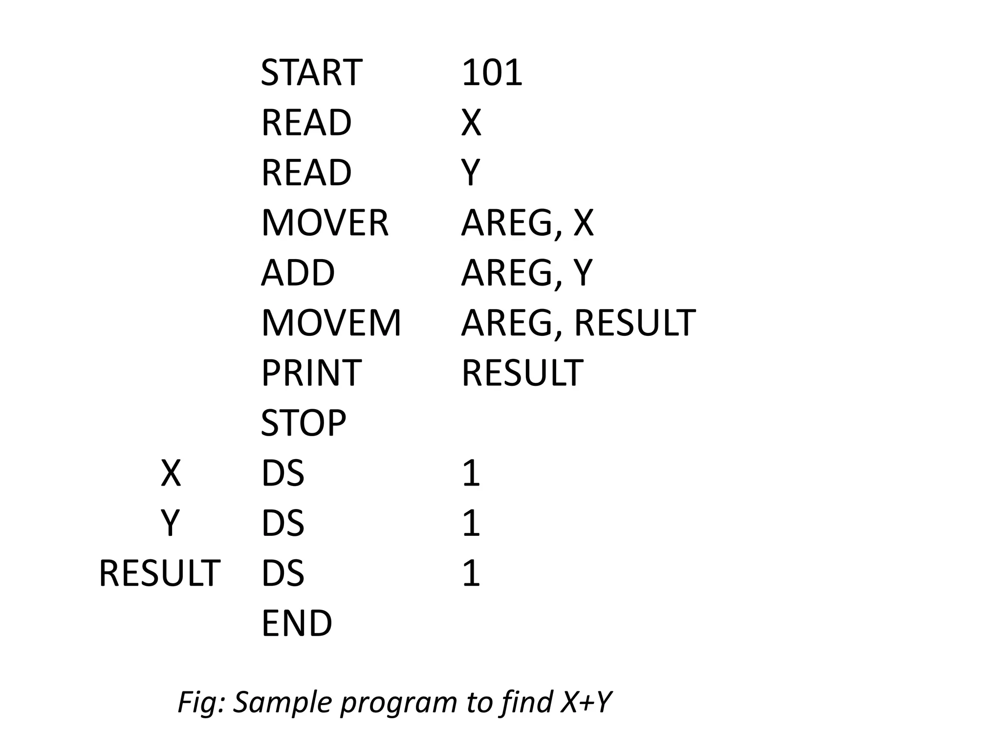
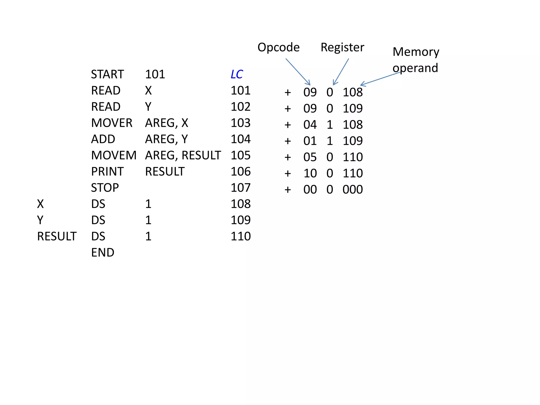
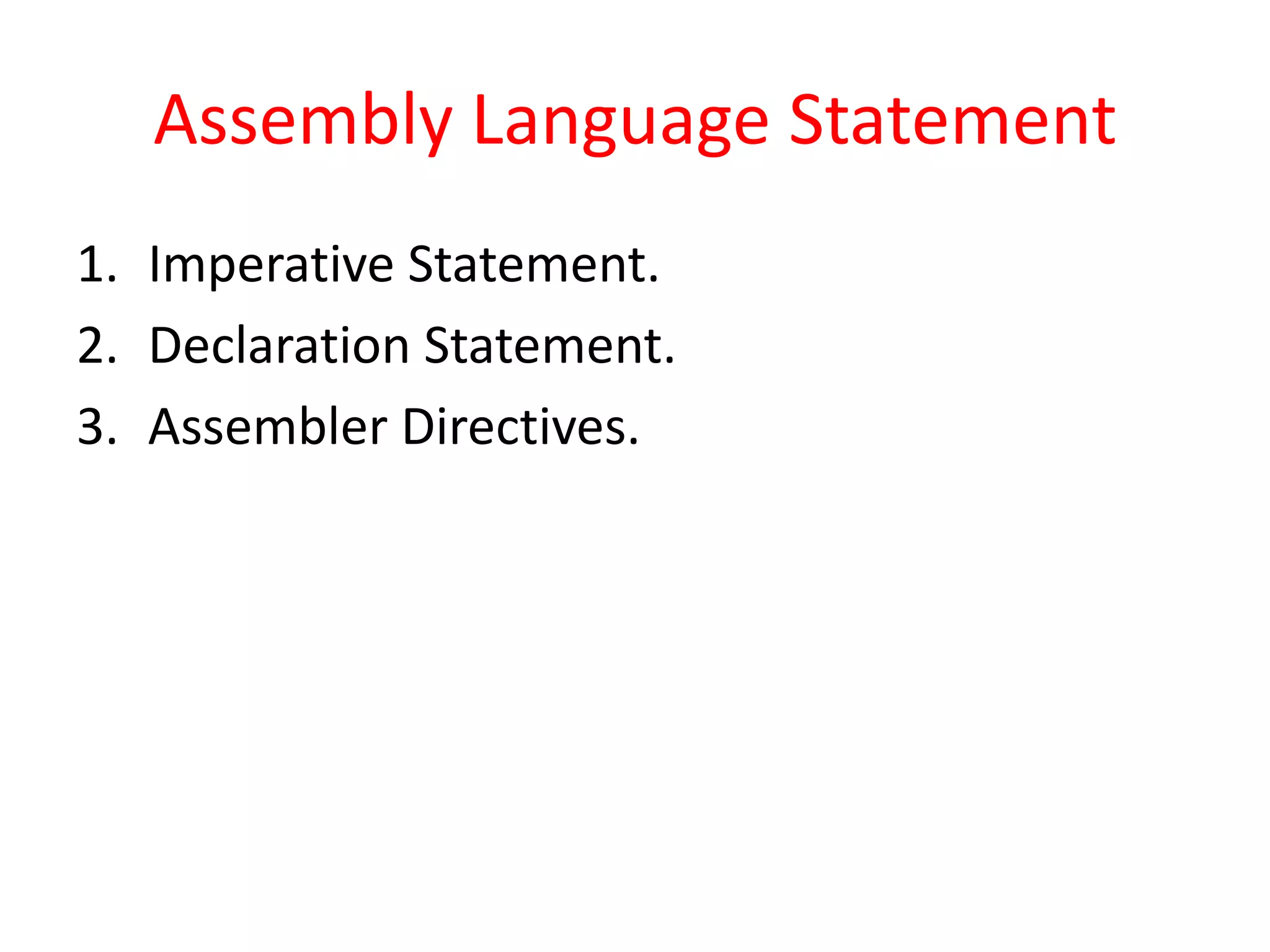
![• Imperative Statements:-
– Indicates an action to be taken during execution of a
program.
– Eg: MOV, ADD, MULT, etc.
• Declaration Statement:-
– To reserve memory for variable.
[Label] DS <constant> eg: X DS 5
[Label] DC ‘<value>’ eg: X DC 3
• Assembler Directives:-
– Instructs the assembler to perform ceratin action during
assembly of a program.
START <constant>
END](https://image.slidesharecdn.com/assemblers-140416005114-phpapp02/75/Assemblers-15-2048.jpg)

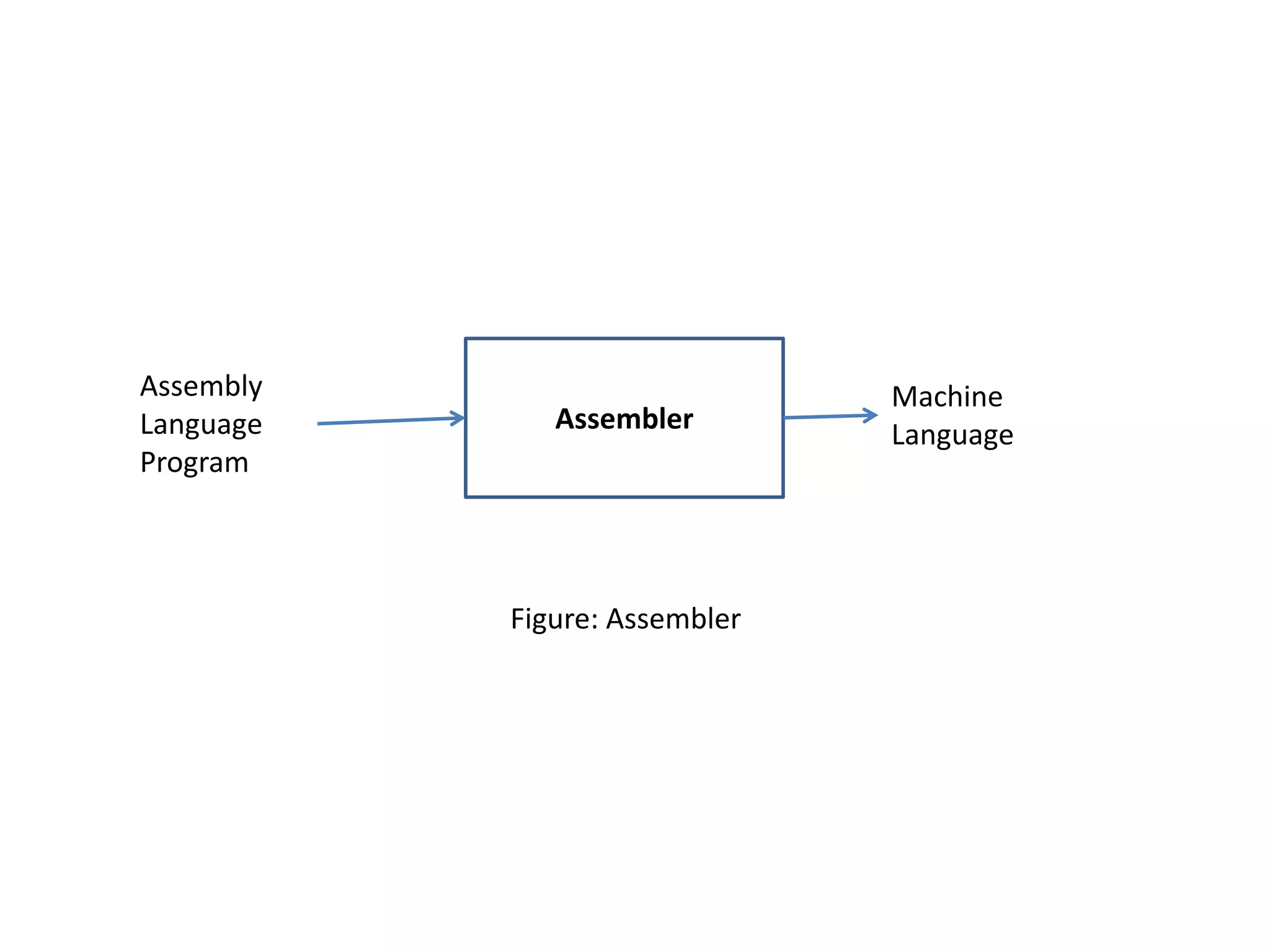
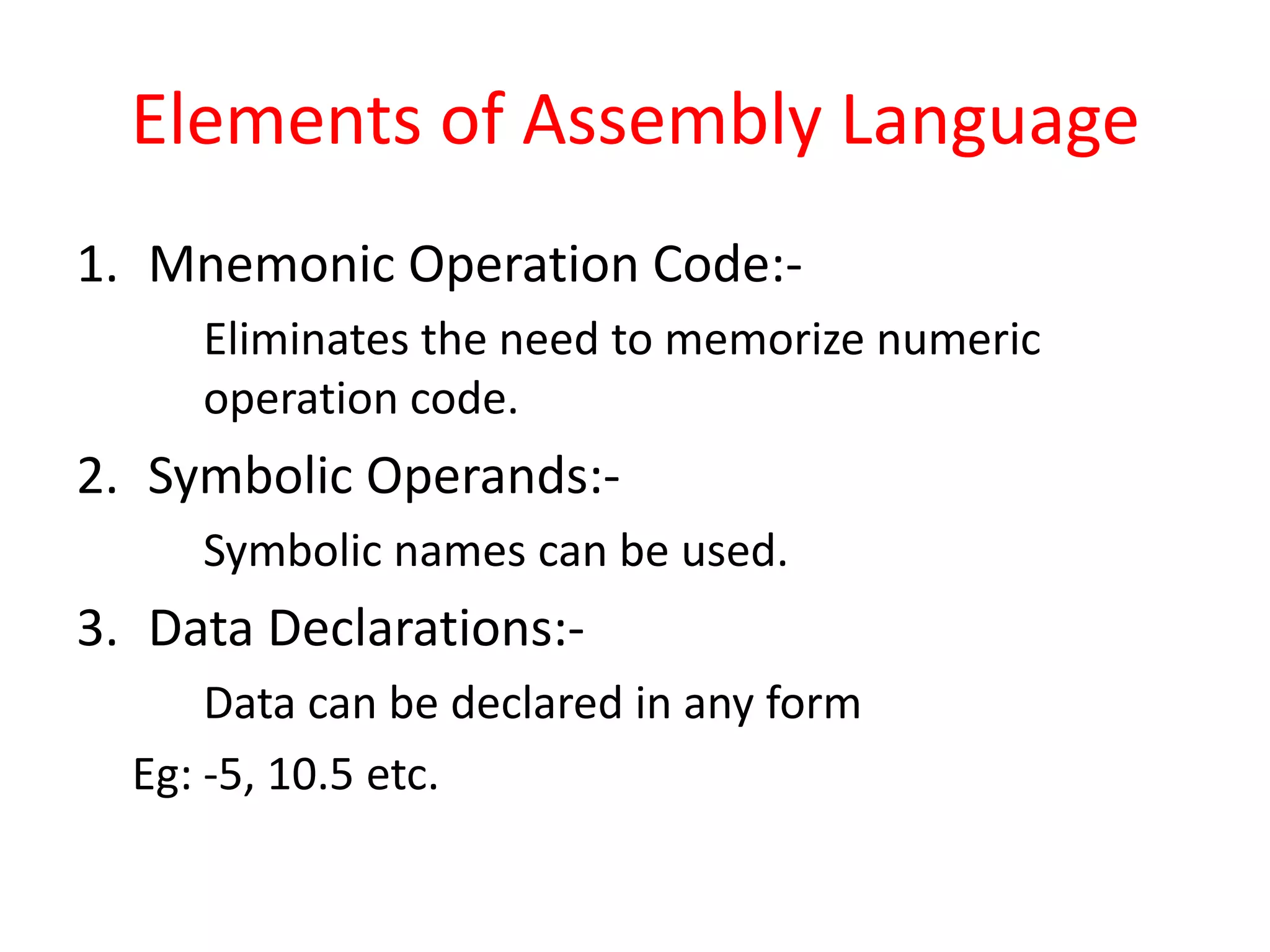
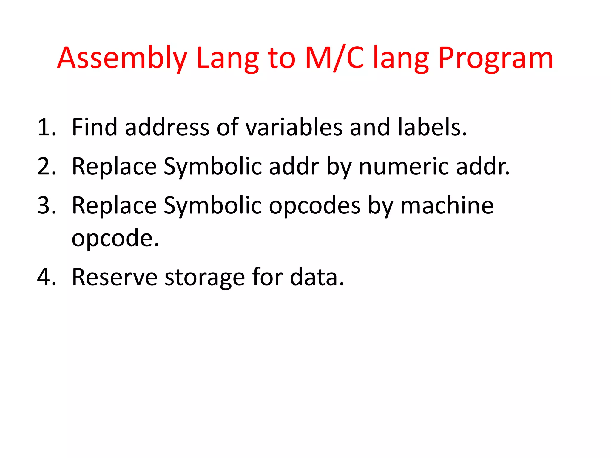
This document discusses assembly language and assemblers. It begins by explaining that assembly language provides a more readable and convenient way to program compared to machine language. It then describes how an assembler works, translating assembly language programs into machine code. The elements of assembly language are defined, including mnemonic operation codes, symbolic operands, and data declarations. The document also covers instruction formats, sample assembly language programs, and the processing an assembler performs to generate machine code from assembly code.