Vibration level switch
•
2 likes•362 views

The Rosemount 2120 is a vibrating fork liquid level switch with several key features: - It functions unaffected by process variations like flow, bubbles, or viscosity. - It has adjustable switching delay to prevent false alarms in turbulent applications. - It requires minimal installation and no calibration after installation.

Recommended
More Related Content
What's hot
What's hot (20)
Similar to Vibration level switch
Similar to Vibration level switch (20)
Recently uploaded
Recently uploaded (20)
Vibration level switch
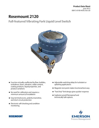
- 1. Product Data Sheet June 2013 00813-0100-4030, Rev GB Rosemount 2120 Full-featured Vibrating Fork Liquid Level Switch Function virtually unaffected by flow, bubbles, turbulence, foam, vibration, solids content, coating products, liquid properties, and product variations Adjustable switching delay for turbulent or splashing applications Magnetic test point makes functional test easy No need for calibration and requires a minimum amount of installation “Fast Drip” fork design gives quicker response Explosion-proof/Flameproof and Intrinsically Safe options Easy terminal access, polarity insensitive, and short circuit protection Electronic self-checking and condition monitoring
- 2. Rosemount 2120 June 2013 Overview of the Rosemount 2120 Measurement principle The Rosemount 2120 is designed using the principle of a tuning fork. A piezo-electric crystal oscillates the forks at their natural frequency. Changes to this frequency are continuously monitored. The frequency of the vibrating fork sensor changes depending on the medium in which it is immersed. The denser the liquid, the lower the frequency. When used as a low level alarm, the liquid in the tank or pipe drains down past the fork, causing a change of natural frequency that is detected by the electronics and switches the output state. Adjustable Mode and Switching Delay When the 2120 is used as a high level alarm, the liquid rises in the tank or pipe, making contact with the fork which then causes the output state to switch. Key features and benefits The 2120 is designed for operation in process temperatures from –40 to 302 °F (–40 to 150 °C) A ‘heartbeat’ LED indicates its operating state. The LED also flashes when the switch output is ‘off’ and is constantly lit when 'on' Adjustable switching delay prevents false switching in turbulent or splashing applications ‘Fast Drip’ fork design gives quicker response time, especially with viscous liquids Rapid wet-to-dry and dry-to-wet time setting for highly responsive switching Fork shape is optimized for hand polishing to meet hygienic requirements ‘Fast Drip’ Forks Virtually unaffected by turbulence, foam, vibration, solids content, coating products, or liquid properties No moving parts or crevices for virtually no maintenance Contents Overview of the Rosemount 2120 . . . . . . . . . . . . . . page 2 Product certifications . . . . . . . . . . . . . . . . . page 11 Rosemount 2120 level switch ordering . . . . . . . . . page 4 Dimensional drawings . . . . . . . . . . . . . . . . page 13 Specifications . . . . . . . . . . . . . . . . . . . . . . . . . . . . . . . page 8 2 www.rosemount.com
- 3. June 2013 Rosemount 2120 Fit and forget Once installed, the 2120 is ready to go. It needs no calibration and requires minimum installation The ‘heartbeat’ LED gives an instant visual indication that the unit is operational Functional testing of the instrument and system is easy with a magnetic test point High And Low Level Alarm You can install, and forget it Superior performance The 2120 is a popular choice for high and low level alarm and pump control duties for its simplicity, ease of use, and reliability Functionality is virtually unaffected by flow, turbulence, bubbles, foam, or vibration The ‘Fast Drip’ design allows the liquid to be quickly drawn away from the fork tip when mounted horizontally, making the 2120 quicker and more responsive in high density or viscous liquid applications High-temperature Applications With a user-selectable time delay feature, the risk of false switching is minimized in turbulent or splashing applications Applications Overfill protection High and low level alarms Pump control or limit detection Run dry or pump protection Hygienic applications High-temperature applications Wireless applications Pump Control / Limit Detection Wireless Applications using a Rosemount 702 Discrete Transmitter www.rosemount.com 3
- 4. Rosemount 2120 June 2013 Rosemount 2120 level switch ordering Table 1. 2120 ordering information ★The Standard offering represents the most common models and options. These options should be selected for best delivery. The Expanded offering is manufactured after receipt of order and is subject to additional delivery lead time. Model Product Description 2120 Vibrating Fork Liquid Level Switch / –40…302 °F (–40...150 °C) Materials of Construction: Process Connection/Fork Standard Standard ★ D 316/316L Stainless Steel (1.4401/1.4404) dual certified Expanded F(1) ECTFE/PFA copolymer, coated 316/316L SST (1.4401/1.4404) C(2) Alloy C (UNS N10002), Alloy C-276 (UNS N10276), Solid Process Connection Size / Type Standard Standard 0A 3/4-in. BSPT (R) Thread ★ 0B 3/4-in. BSPP (G) Thread ★ 0D 3/4-in. NPT Thread ★ 1A 1-in. BSPT (R) Thread ★ 1B 1-in. BSPP (G) Thread ★ 1D 1-in. NPT Thread – (2-in. NPT Thread available by adding “R2105” to the model number ) ★ 1P 1-in. BSPP (G), O-ring, Hygienic Fitting ★ 5R 11/2-in. (38 mm) Tri-Clamp, Hygienic Fitting ★ 2R 2-in. (51 mm) Tri-Clamp, Hygienic Fitting ★ 1G 1-in. ASME B16.5 Class 150 Raised Face (RF) Flange ★ 1H 1-in. ASME B16.5 Class 300 Raised Face (RF) Flange ★ 1J 1-in. ASME B16.5 Class 600 Raised Face (RF) Flange ★ (3) 5G 1 /2-in. ASME B16.5 Class 150 Raised Face (RF) Flange ★ 5H 11/2-in. ASME B16.5 Class 300 Raised Face (RF) Flange ★ 2G 2-in. ASME B16.5 Class 150 Raised Face (RF) Flange ★ 2H 2-in. ASME B16.5 Class 300 Raised Face (RF) Flange ★ 3G 3-in. ASME B16.5 Class 150 Raised Face (RF) Flange ★ 3H 3-in. ASME B16.5 Class 300 Raised Face (RF) Flange ★ 4G 4-in. ASME B16.5 Class 150 Raised Face (RF) Flange ★ 4H 4-in. ASME B16.5 Class 300 Raised Face (RF) Flange ★ 1K DN25, EN1092 PN 10/16 Flange ★ 1L DN25, EN1092 PN 25/40 Flange ★ 1M DN25, EN1092 PN 63 Flange ★ 1N DN25, EN1092 PN 100 Flange ★ 5K DN40, EN1092 PN 10/16 Flange ★ 5L DN40, EN1092 PN 25/40 Flange ★ 2K DN50, EN1092 PN 10/16 Flange ★ 2L DN50, EN1092 PN 25/40 Flange ★ 7K DN65, EN1092 PN 10/16 Flange ★ 7L DN65, EN1092 PN 25/40 Flange ★ 3K DN80, EN1092 PN 10/16 Flange ★ 3L DN80, EN1092 PN 25/40 Flange ★ 4K DN100, EN1092 PN 10/16 Flange ★ 4L DN100, EN1092 PN 25/40 Flange Expanded ★ 1 5J 11/2-in. ASME B16.5 Class 600 Raised Face (RF) Flange 2J 2-in. ASME B16.5 Class 600 Raised Face (RF) Flange 3J 3-in. ASME B16.5 Class 600 Raised Face (RF) Flange 4 www.rosemount.com
- 5. June 2013 Rosemount 2120 Table 1. 2120 ordering information ★The Standard offering represents the most common models and options. These options should be selected for best delivery. The Expanded offering is manufactured after receipt of order and is subject to additional delivery lead time. 4J 4-in. ASME B16.5 Class 600 Raised Face (RF) Flange 5M DN40, EN1092 PN 63 Flange 5N DN40, EN1092 PN 100 Flange 2M DN50, EN1092 PN 63 Flange 2N DN50, EN1092 PN 100 Flange 7M DN65, EN1092 PN 63 Flange 7N DN65, EN1092 PN 100 Flange 3M DN80, EN1092 PN 63 Flange 3N DN80, EN1092 PN 100 Flange 4M DN100, EN1092 PN 63 Flange 4N DN100, EN1092 PN 100 Flange SA 25A, 10K, JIS B2220 Flange SB 25A, 20K, JIS B2220 Flange TA 40A, 10K, JIS B2220 Flange TB 40A, 20K, JIS B2220 Flange UA 50A, 10K, JIS B2220 Flange UB 50A, 20K, JIS B2220 Flange VA 80A, 10K, JIS B2220 Flange VB 80A, 20K, JIS B2220 Flange ZA 100A, 10K, JIS B2220 Flange ZB 100A, 20K, JIS B2220 Flange XX(4) Customer Specific Electronic Type Available Certifications Standard Standard T Direct load switching (Mains 2-wire) 20 to 264 Vac 50/60Hz, 20 to 60 Vdc NA, E1, E2, E5, E6, E7, G5, G6 ★ G PNP/PLC low voltage (3-wire) 20 to 60 Vdc NA, E1, E2, E5, E6, E7, G5, G6 ★ V Relay DPCO – (9...30 Vdc version available by adding “R2257” to model number(3)(5)) NA, E1, E2, E5, E6, E7, G5, G6 ★ K NAMUR All ★ H 8/16 mA All ★ Surface Finish Available Connections Standard Standard 1 2 All Hand polished (Ra < 0.4 μm) Product Certifications ★ Hygienic Connection Only Standard surface finish ★ Electronic Types Allowed Available Housings All except 9...30 Vdc Relay All ★ Standard Standard NA No Hazardous Locations Certifications G5(6) FM Ordinary Locations (unclassified, safe area) All Y, T ★ G6(7) CSA Ordinary Locations (unclassified, safe area) All except 9...30 Vdc Relay Y, T ★ E1 ATEX Flameproof All except 9...30 Vdc Relay X, S ★ E2 INMETRO Flameproof All except 9...30 Vdc Relay X, S ★ E5(6) FM Explosion-proof All Y, T ★ E6(7) CSA Explosion-proof All except 9...30 Vdc Relay Y, T ★ E7 IECEx Explosion-proof All except 9...30 Vdc Relay X, S ★ I1 ATEX Intrinsic Safety K, H All ★ I2 INMETRO Intrinsic Safety K, H All ★ I5 FM Intrinsic Safety K, H All ★ CSA Intrinsically Safe K, H All ★ IECEx Intrinsic Safety K, H All ★ I6 I7 www.rosemount.com 5
- 6. Rosemount 2120 June 2013 Table 1. 2120 ordering information ★The Standard offering represents the most common models and options. These options should be selected for best delivery. The Expanded offering is manufactured after receipt of order and is subject to additional delivery lead time. Housing Available for Certifications Standard Standard A Glass Filled Nylon, M20 conduits/cable threads NA, I1, I2, I5, I6, I7 ★ D Glass Filled Nylon, 1/2-in. NPT conduits/cable threads NA, I1, I2, I5, I6, I7 ★ X Aluminum Alloy, M20 conduits/cable threads All except G5, G6, E5, E6 ★ Y Aluminum Alloy, 3/4-in. NPT conduits/cable threads All except E1, E2, and E7 ★ S Stainless Steel, M20 conduits/cable threads All except G5, G6, E5, E6 ★ T Stainless Steel 3/4-in. NPT conduits/cable threads All except E1, E2, and E7 ★ Fork Length Available Connection Standard A Standard length 1.7 in. (44 mm) H(8) E Standard (9) All except flanged and 2-in. NPT ★ All flanged models ★ All except 1-in. BSPP O-ring (1P) ★ All except 1-in. BSPP O-ring (1P) ★ Standard length flange 4.0 in. (102 mm) Extended, customer specified length in tenths of inches (9) M Extended, customer specified length in millimeters Specific Extended Fork Length Standard Standard 0000 Factory default length (only if Fork Length A or H is selected) ★ XXXX(9) OPTIONS Specific customer specified length in tenths of inches, or millimeters (XXXX mm or XXX.X inches) ★ Calibration Data Certification Standard Standard ★ Q4 Certificate of functional test Material Traceability Certification Standard Standard ★ Q8(8)(10) Material traceability certification per EN 10204 3.1 Material Certification Standard Q15(8)(10) Standard ★ NACE MR0175 / ISO 15156 ★ Q25(8)(10) NACE MR0103 Special Procedures Standard Standard ★ P1(11) Hydrostatic testing with certificate Typical Model Number: 2120 D 0A K 1 I1 A 0000 Q8 (1) ECTFE/PFA copolymer coating is only available for a flanged 2120 but excludes 1-in./DN25/25A flanges. Flanges are dual certified 316 and 316L Stainless Steel (1.4401 and 1.4404). (2) Available for threaded process connection codes 0A, 0D, 1A, and 1D and flanged process connections as standard, other upon request. (3) For a combination of 2-in. threaded process connection and 9 to 30 Vdc (12 Vdc nominal) version of the Relay electronics, add “R2258” to the model code. (4) Other process connections available upon request. (5) The 9 to 30 Vdc (12 Vdc nominal) version of the Relay electronics is available with Product Certification codes G5 or E5. (6) See “Product certifications” on page 11. E5 includes G5 requirements. G5 is for use in unclassified, safe area locations only. (7) See Product Certifications on page page 11. E6 includes G6 requirements. G6 is for use in unclassified, safe area locations only. (8) Not available for hand polished wet side. (9) Minimum length available for 3/4-in. threaded connection is 3.8 in. (95 mm); for 1-in. and 2-in. threaded, it is 3.7 in. (94 mm); for flanged, it is 3.5 in. (89 mm); and for Tri-Clamp, it is 4.1 in. (105 mm). Maximum length is 157.5 in. (4000 mm), except for ECTFE/PFA copolymer coating and hand-polished process where the maximum length is 59.1 in. (1500 mm) and 39.4 in. (1000 mm) respectively. Examples: Code E1181 is 118.1 inches. Code M3000 is 3000 millimeters. (10) Only available for wetted parts. (11) Option limited to units with extended lengths up to 59.1-in. (1500 mm). Option is not available for ECTFE/PFA coating. 6 www.rosemount.com
- 7. June 2013 Rosemount 2120 Spare parts and accessories Table 2. Spare parts and accessories ★The Standard offering represents the most common models and options. These options should be selected for best delivery. The Expanded offering is manufactured after receipt of order and is subject to additional delivery lead time. Spares and Accessories (1) (2) Standard Standard 02100-1000-0001 Seal for 1-in. BSPP (G1A). Material: Non-asbestos BS7531 grade X carbon fiber with rubber binder ★ 02100-1040-0001 Seal for 3/4-in. BSPP (G3/4A). Material: Non-asbestos BS7531 grade X carbon fiber with rubber binder ★ 02100-1010-0001 Hygienic adaptor boss 1-in. BSPP. Material: 316 SST fitting. FPM/FKM O-ring ★ 02100-1020-0001 2-in. (51 mm) Tri-clamp kit (vessel fitting, clamp ring, and seal). Material: 316 SST, NBR Nitrile ★ 02100-1030-0001 Telescopic test magnet ★ 02120-2000-0001(3) 11/2-in. BSPP adjustable 316 SST clamp gland for 1-in. extended lengths. Silicone (Si) rubber seal ★ 02120-2000-0002(3) 11/2-in. NPT adjustable 316 SST clamp gland for 1-in. extended lengths. Silicone (Si) rubber seal ★ 02120-7000-0001 Replacement Cassette: Direct load switching (2 Wire) (Red) ★ 02120-7000-0002 Replacement Cassette: PNP/PLC, low voltage (Yellow) ★ 02120-7000-0003 Replacement Cassette: NAMUR (Light Blue) ★ 02120-7000-0004 Replacement Cassette: Relay (DPCO), standard version (Green) ★ 02120-7000-0005 Replacement Cassette: 8/16 mA output (Dark Blue) ★ 02120-7000-0007 Replacement Cassette: Relay (DPCO), 9...30 Vdc (12 Vdc nominal) version (Green) ★ (1) Check the Electronic Type and Product Certification sections in Table 1 on page 4 for availability conditions. (2) Intrinsically Safe (IS) approved cassettes can only be replaced with the same type of IS cassette. Non-IS cassette types can be interchanged with other non-IS cassettes, but the new label must be fitted and the original part number transferred to the new label. (3) The adjustable clamp gland is not explosion-proof. www.rosemount.com 7
- 8. Rosemount 2120 June 2013 Specifications Gasket material for 3/4-in. and 1-in. BSPP (G) is non-asbestos BS7531 Grade X carbon fiber with rubber binder General Dimensional drawings See “Dimensional drawings” on page 13 Product Rosemount 2120 Full-featured Vibrating Fork Liquid Level Switch Measuring principle Performance Hysteresis (water) Vibrating Fork ±0.039-in. (±1 mm) nominal Applications Most liquids including coating liquids, aerated liquids, and slurries Switching point (water) 0.5 in. (13 mm) from tip (vertical) / from edge (horizontal) of fork (this will vary with different liquid densities) Mechanical Functional Housing / Enclosure Maximum operating pressure Table 3. Housing / Enclosure specification The final rating depends on the selected process connection A Housing Material Nylon PA66 30%GF LED Window Conduit Entry Ingress Protection X Y Al alloy ASTM B85 A360.0 S T 316C12 SST Yes No No Not Applicable Nylon PA12 Polyurethane Paint None Not Applicable None Rotational Housing Paint D 1 /2-in. NPT IP66/67 to EN60529 M20 M20 3 /4-in. NPT IP66/67 to EN60529, NEMA 4X M20 3 /4-in. NPT IP66/67 to EN60529, NEMA 4X Connections Threaded, hygienic, and flanged process connections. See “Process Connection Size / Type” on page 4 for a complete list Extended lengths The maximum extended length is 157.5 in. (4000 mm) except for ECTFE/PFA copolymer coating and hand-polished process connection options which have a maximum length of 59.1 in. (1500 mm) and 39.4 in. (1000 mm) respectively Threaded connection: see Figure 1 for operating pressures Note: Clamp glands 02120-2000-0001 and 02120-2000-0002 (page 7) limit the maximum pressure to 18.85 psig (1,3 bar g) Hygienic connection: 435 psig (30 bar g) Flanged connection: See Figure 1 or Table 5 (whichever gives the lowest pressure) Figure 1. Process pressure Process Pressure psig (barg) Housing Code 1450 (100) 1160 (80) 32 (0) -14.5 (-1.0) -40 32 (-40) (0) 122 (50) 302 Process (150) Temperature °F (°C) Table 5. Maximum flange pressure rating Table 4. Minimum extended lengths Standard Class/Rating SST Flanges ASME B16.5 Class 150 275 psig(1) ASME B16.5 Class 300 720 psig(1) Process Connection Minimum Extended Length ASME B16.5 Class 600 1440 psig(1) 3/4–in. Threaded 3.8 in. (95 mm) EN1092-1 PN 10 10 barg(2) 1–in. and 2-in. Threaded 3.7 in. (94 mm) EN1092-1 PN 16 16 barg(2) Flanged 3.5 in. (89 mm) EN1092-1 PN 25 25 barg(2) Tri-Clamp 4.1 in. (105 mm) EN1092-1 PN 40 40 barg(2) EN1092-1 PN 63 63 barg(2) Process connection materials EN1092-1 PN 100 100 barg(2) 316/316L Stainless Steel (1.4401/1.4404 dual certified) JIS B2220 10K 14 barg(3) Alloy C (UNS N10002) and Alloy C-276 (UNS N10276) JIS B2220 20K 34 barg(3) – available for flanged, and BSPT and NPT threaded process connections (3/4-in. and 1-in. BSPT (R), and 3/4-in. and 1-in. NPT) ECTFE/PFA co-polymer coated 316/316L Stainless Steel (1.4401/1.4404 dual certified) – only available for a flanged 2120 but excludes 1-in./DN25/25A flanges Hand-polished to better than 0.4 m option for hygienic connections 8 (1) At 100 °F (38 °C), the rating decreases with an increasing process temperature. (2) At 122 °F (50 °C), the rating decreases with an increasing process temperature. (3) At 248 °F (120 °C), the rating decreases with an increasing process temperature. www.rosemount.com
- 9. June 2013 Rosemount 2120 Minimum and maximum operating temperatures See Figure 2 for operating temperatures Clamp glands 02120-2000-0001 and 02120-2000-0002 (page 7) limit the maximum temperature to 257 °F (125 °C) The ambient temperature for a 8/16 mA cassette is limited to 158 °F (70 °C) in dust applications Electrical Switching mode User selectable switching mode (Dry=on or Wet=on) Protection Polarity insensitive – Relay (except 12 Vdc nominal version) and Direct Load electronics Figure 2. Operating temperatures Ambient Temperature °F (°C) Over-current protection – Direct Load and PNP/PLC electronics Short-circuit protection – Direct Load and PNP/PLC electronics Load-missing protection – Direct Load and PNP/PLC electronics 176 (80) Surge protection (to IEC61326) – Direct Load and PNP/PLC electronics 122 (50) Heartbeat LED The 2120 has a status-indicating heartbeat LED, which can be seen at 32 (0) -40 (-40) all times and from all angles through a lens in the cover (no lens in metal housings) -40 32 (-40) (0) 140 (60) 302 (150) Process Temperature °F (°C) Liquid density requirement Minimum 37.5 lb/ft3 (600 kg/m3) Liquid viscosity range 0.2 to 10000 cP (centiPose) Solids content and coating Maximum recommended diameter of solid particles in the liquid is 0.2 in. (5 mm) For a coating product, avoid bridging of forks Switching delay User selectable 0.3, 1, 3, 10, 30 seconds delay for dry-to-wet and wet-to-dry switching CIP (Clean In Place) and SIP (Steam In Place) cleaning Withstands cleaning routines up to 275 °F (135 °C) The LED flashes when the output is ‘off’ and is constantly lit when it is ‘on’. The LED gives a constant indication that the 2120 is functioning correctly (different flash rates are used to indicate a product malfunction) and gives a local indication of the process state Magnetic test point A magnetic test point is located on the side of the housing, allowing a functional test of the 2120 and a system connected to it. By holding a magnet to the target, the 2120 output changes state for as long as the magnet is held there Terminal connection (wire diameter) Minimum 26 AWG, Maximum 14 AWG (0.13 to 2.5 mm2). Note national regulations. Conduit plugs/cable gland Metal housing: Conduit entries for explosion-proof areas are shipped with one Exd plug (loose in bag) and two dust caps fitted. Use suitably rated cable glands. Unused conduit entries must be sealed with a suitably rated blanking plug Glass-filled nylon housing with direct load, PNP/PLC and IS electronics NACE NACE compliance to MR0175 / ISO 15156 or MR0103, depending on the option code selected for the model number are shipped with one PA66(1) cable gland and one blanking plug Glass-filled nylon housing with relay electronics are shipped with two PA66(1) cable glands Grounding The 2120 must always be grounded either through the terminals or using the external ground connection provided. (1) www.rosemount.com Cable diameter 0.2 to 0.3 in. (5 to 8 mm) 9
- 10. Rosemount 2120 June 2013 Electrical connections DPCO dual relay cassette (standard version). Direct load switching (mains two wire) cassette. Electronic Type code V (see Table 1 on page 4) LOAD LINE Dry On Wet On 0.3 1 3 L 0.3 1 3 10 WARNING 3 10 Dry Wet 10 30 30 Isolate Supply Before Removing Seconds Delay Dry On Dry On Wet On Dry N 0.3 1 OPERATION MODE Warning Direct Load Switching OPERATION MODE Dry On Mode Dry Wet C NO NC C NO 3 10 Dry 30 Wet 30 Isolate Supply Before Removing NC 0.3 Wet 1 RELAY Electronic Type code T (see Table 1 on page 4) Wet On 1 2 3 R PE (Ground) Fuse 2A(T) PE (Ground) R = External load (must be fitted ) IL Neutral Live N 0V +V 6 7 8 9 NO NC C NO IMAX = 5 A ac: UMAX = 250 V PMAX = 875 VA dc: UMAX = 30 V PMAX = 240 W (dc) ac: UMAX = 250 V PMAX = 1250 VA dc: UMAX = 30 V U = 20...264 V ~ (ac) (50/60 Hz) I < 6 mA U = 20...60 V I < 6 mA Inductive Load cos φ = 0.4 ; L/R = 7 ms IMAX = 3.5 A PMAX = 170 W DPCO dual relay cassette (12 Vdc nominal version). NAMUR (light blue) cassette. Electronic Type code V (see Table 1 on page 4) Electronic Type code K (see Table 1 on page 4) 12 VDC NOM. OPERATION MODE Dry On Mode Dry Wet + Live 5 C Resistive Load cos φ = 1 ; L/R = 0 ms DPST U = 20 - 60 V (dc) IOFF < 4 mA IL = 20 - 500 mA IPK = 5 A, 40 ms (inrush) +V - Fuse 0.5 (T) U = 20 - 264 V ~ (ac) (50/60Hz ) IOFF < 4 mA IL = 20 - 500 mA IPK = 5 A, 40 ms (inrush) DPST 0V Seconds Delay Wet On Mode 3 Dry On Wet On Dry Wet Isolate Supply Before Removing OPERATION MODE Seconds Delay Dry On Dry On Wet On Dry + 0.3 1 0.3 1 3 10 30 8V dc 0.3 1 EN 50227 / NAMUR 3 10 30 NC C NO NC C NO 0.3 Wet 1 3 10 30 RELAY 2 4 NC 1 3 10 Dry 30 Wet Wet On 2 Wet On Mode 1 Seconds Delay 3 PE (Ground) ION = 2.2 ... 2.5 mA Ex 2 4 Fuse 0.5 (T) A certified intrinsically safe isolating amplifier to IEC 60947-5-6 8/16 mA (dark blue) cassette. Dry On Wet On Mode Ex - ac: UMAX = 125 V PMAX = 37.5 VA dc: UMAX = 30 V PMAX = 30 W 0.3 1 8/16 mA + OUT - 0.3 1 Dry On Mode Dry Wet Dry On 0.3 1 Wet On 0.3 1 3 10 30 Dry Wet Seconds Delay 1 3 2 PE (Ground) = 15 ... 17 mA U = 24 Vdc Nominal I OFF = 7.5 ... 8.5 mA +V 3 4 10 30 O/P 0V 30 Wet On Mode U = 20 - 60 V I < 4 mA + I L Isolate Supply Before Removing 3 10 3 10 30 PLC/PNP OPERATION MODE Wet On 3 Wet Dry Ex Inductive Load cos φ = 0.4 ; L/R = 7 ms IMAX = 1 A Electronic Type code G (see Table 1 on page 4) Fuse 2A(T) Dry On Mode Dry Wet I ON (dc) +V OPERATION MODE PE (Ground) NO Solid state PNP output for direct interface to a PLC. Electronic Type code H (see Table 1 on page 4) 2 9 C PMAX = 60 W U = 9...30 V I < 4 mA 0V 1 8 NC PMAX = 62.5 VA dc: UMAX = 30 V DPST + 7 NO Resistive Load cos φ = 1 ; L/R = 0 ms IMAX = 2 A + Ex 6 C ac: UMAX = 125 V IOFF = 0.8 ... 1.0 mA - 5 NC 1 Seconds Delay (dc) IL (MAX) = 0 - 500 mA IPK = 5 A, 40 ms (inrush) UOUT(ON) = U - 2.5 V IL (OFF) < 100 A + A certified intrinsically safe barrier must be used to meet IS requirements - + Drives 4-20 mA Analog Input 10 www.rosemount.com
- 11. June 2013 Rosemount 2120 Product certifications European directive information Hazardous locations certifications The EC declaration of conformity for all applicable European directives for this product can be found on the Rosemount website at www.rosemount.com. A hard copy may be obtained by contacting your local sales office. North american approvals Factory Mutual (FM) explosion-proof approval E5 ATEX Directive (94/9/EC) Complies with the ATEX Directive. Pressure Equipment Directive (PED) (97/23/EC) Project ID: 3012658 Explosion-proof for Class I, Div. 1, Groups A, B, C, and D Temperature Class: T6 (Tamb –40 to 75 °C) Enclosure: Type 4X The Rosemount 2120 is outside the scope of PED Directive. Factory Mutual (FM) intrinsically safe approval and non-incendive L.V. Directive I5 EN61010-1 Pollution degree 2, Category II (264 V maximum), Pollution degree 2, Category III (150 V maximum) Electro Magnetic Compatibility (EMC) Directive EN61326 Emissions to Class B. Immunity to industrial location requirements. CE-mark Complies with applicable directives (EMC, ATEX, and LVD) Ordinary location certification for FM G5 Project ID: 3021776 The switch has been examined and tested to determine that the design meets basic electrical, mechanical, and fire protection requirements by FM, a nationally recognized testing laboratory (NRTL) as accredited by the Federal Occupational Safety and Health Administration (OSHA). NOTE A certified isolating amplifier or barrier must be used for intrinsic safety. Canadian approvals Canadian Standards Association (CSA) explosion-proof E6 Certificate Number: 06 CSA 1805769 The switch has been examined and tested to determine that the design meets basic electrical, mechanical, and fire protection requirements by CSA, a nationally recognized testing laboratory as accredited by the Standards Council of Canada (SCC). Single seal Canadian Registration Number CRN 0F04227.2C NOTE The requirements of CRN are met when a Rosemount 2120 CSA IS-approved (I6 code) vibrating fork level switch model is configured with 316/316L stainless steel (1.4401/1.4404) wetted parts and either NPT threaded or 2 to 8-in. ASME B16.5 flanged process connections. www.rosemount.com Project ID: 1786345 Explosion-proof for Class I, Div. 1, Groups A, B, C, and D Temperature Class: T6 (Tamb –40 to 75 °C) Enclosure: Type 4X Single seal Ordinary location certification for CSA G6 Project ID: 3011456 Intrinsically Safe for Class I, Div. 1, Groups A, B, C, and D Class I, Zone 0, AEx ia IIC Non-incendive for Class I, Div. 2, Groups A, B, C, and D Class I, Zone 2, IIC Temperature Code: T5 (Tamb –40 to 80 °C, Tproc < 80 °C) Control Drawing: 71097/1154 (with NAMUR electronics) Control Drawing: 71097/1314 (with 8/16 mA electronics) Canadian Standards Association (CSA) intrinsically safe and non-incendive I6 Certificate Number: 06 CSA 1786345 Intrinsically Safe for Class I, Div. 1, Groups A, B, C, and D Class 1, Zone 0, Ex ia IIC Non-Incendive for Class I, Div. 2, Groups A, B, C, and D Temperature Code: T5 (Tamb –40 to 80 °C, Tproc < 80 °C) Control Drawing: 71097/1179 (with NAMUR electronics) Control Drawing: 71097/1315 (with 8/16 mA electronics) Single seal NOTE A certified isolating amplifier or barrier must be used for intrinsic safety. 11
- 12. Rosemount 2120 June 2013 European approvals International approvals ATEX flameproof approval INMETRO flameproof approval E1 E2 Certificate: Sira 05ATEX1129X Flameproof and Dust: ATEX Marking II 1/2 G D Ex d IIC T6...T2 Ga/Gb Ex tb IIIC T85 °C...T265 °C Db ATEX intrinsically safe approval I1 Certificate: Sira 05ATEX2130X Intrinsic Safety and Dust: ATEX Marking II 1 G D Ex ia IIC T5...T2 Ga Ex ia IIIC T85 °C...T265 °C Da NOTE A certified isolating amplifier or barrier must be used for intrinsic safety. Certificate Number: TÜV 12.1285 X Flameproof and Dust: Ex d IIC T6 to T2 Gb, Ex tb IIIC T85 °C to T265 °C Db Ex d IIC T6 to T2 Ga/Gb, Ex tb IIIC T85 °C to T265 °C Db INMETRO intrinsically safe approval I2 Certificate Number: TÜV 12.1391 X Intrinsically Safe and Dust: Ex ia IIC T* Ga, Ex ia IIIC T* Da (* See table in the certificate) Ta* (* See table in the certificate) Security parameters: NAMUR: Ui = 15 V / Ii = 32 mA / Pi = 0,1 W / Ci = 12 nF / Li = 0,06 mH 8/16 mA: Ui = 30 V / Ii = 93 mA / Pi = 0,65 W / Ci = 12 nF / Li = 0,035 mH Safe use special condition: Non-metallic parts of the equipment casing can generate electrostatic charges under extreme conditions. The equipment should only be cleaned with a damp cloth. NOTE A certified isolating amplifier or barrier must be used for intrinsic safety. International Electrotechnical Commission (IEC) flameproof approval E7 Certificate: IECEx SIR 06.0051X Flameproof and Dust: Ex d IIC T6...T2 Ga/Gb Ex tb IIIC T85°C...T265°C Db International Electrotechnical Commission (IEC) intrinsically safe approval I7 Certificate: IECEx SIR 06.0070X Intrinsically Safe and Dust: Ex ia IIC T5...T2 Ga Ex ia IIIC T85 °C...T265 °C Da NOTE A certified isolating amplifier or barrier must be used for intrinsic safety. 12 www.rosemount.com
- 13. June 2013 Rosemount 2120 Dimensional drawings 3 /4 and 1-in. threaded mounting (standard length) . . . . . . . . . . . . . . . . . . . . . . . . . . . . . . page 13 3 /4 and 1-in. thread mounting (extended length) . . . . . . . . . . . . . . . . . . . . . . . . . . . . . . . page 14 2-in. thread mounting . . . . . . . . . . . . . . . . . . . . . . . . . . . . . . . . . . . . . . . . . . . . . . . . . . . . page 15 Flange mounting (standard length) . . . . . . . . . . . . . . . . . . . . . . . . . . . . . . . . . . . . . . . . . page 16 Flange mounting (extended length) . . . . . . . . . . . . . . . . . . . . . . . . . . . . . . . . . . . . . . . . . page 17 / and 1-in. threaded mounting (standard length) 3 4 Note: Dimensions are in inches (millimeters) GLASS-FILLED NYLON HOUSING ALUMINUM/SST HOUSING 3.5 (89) Allow 1.2 (30) To Remove Lid Allow 1.2 (30) To Remove Lid 4 (102) 5 (127) A 4.7 (120) 5.9 (151) B C C D 2.7 (69 1.7 (44) 0.5 (13) Switchpoint (When Mounted Horizontally) 0.5 (13) Switchpoint (When Mounted Vertically) 2.7 (69) D 1.7 (44) 0.5 (13) Switchpoint (When Mounted Horizontally) 0.5 (13) Switchpoint (When Mounted Vertically) NOTE: FOR HYGIENIC 2120 DIMENSIONS, SEE TYPE 1 DRAWING DOWNLOADS ON WEB SITE A. Cable Entry M20x1.5 or 1/2-in. NPT B. Cable Entry M20x1.5 or 3/4-in. NPT C. 1.6 (40) A/F Hexagon D. 3/4-in. or 1-in. Thread www.rosemount.com 13
- 14. Rosemount 2120 June 2013 / and 1-in. thread mounting (extended length) 3 4 Note: Dimensions are in inches (millimeters) GLASS-FILLED NYLON HOUSING ALUMINUM/SST HOUSING 3.5 (90) Allow 1.2 (30) To Remove Lid Allow 1.2 (30) To Remove Lid 4 (102) 5.9 (151) A 4.7 (120) B 6.7 (171) C C D D E(M) E(M) Ø1.1 (28) for 1-in. Thread Ø0.9 (23) for 3/4-in. Thread 1.7 (44) Ø1.1 (28) for 1-in. Thread Ø0.9 (23) for 3/4-in. Thread 1.7 (44) 0.5 (13) Switchpoint (When Mounted Horizontally) 0.5 (13) Switchpoint (When Mounted Vertically) 0.5 (13) Switchpoint (When Mounted Vertically) 0.5 (13) Switchpoint (When Mounted Horizontally) NOTE: FOR HYGIENIC 2120 DIMENSIONS, SEE TYPE 1 DRAWING DOWNLOADS ON WEB SITE A. Cable Entry M20x1.5 or 1/2-in. NPT B. Cable Entry M20x1.5 or 3/4-in. NPT C. 1.6 (40) A/F Hexagon D. 3/4-in. or 1-in. Thread Table 6. Fork length for 3/4 and 1-in. threaded 2120 Process Connection 3 /4-in. Thread 1-in. Thread Standard Length Fork Length Code A Minimum Length Fork Length Code E (M) Maximum Length Fork Length Code E (M)(1) 1.7 in. (44 mm) 1.7 in. (44 mm) 3.75 in. (95 mm) 3.74 in. (94 mm) 157.5 in. (4000 mm) 157.5 in. (4000 mm) (1) Maximum extended length of fork with hand-polished option is 39.4 in. (1000 mm). 14 www.rosemount.com
- 15. June 2013 Rosemount 2120 2-in. thread mounting Note: Dimensions are in inches (millimeters) GLASS-FILLED NYLON HOUSING ALUMINUM/SST HOUSING 3.5 (90) Allow 1.2 (30) To Remove Lid Allow 1.2 (30) To Remove Lid 4 (102) 6.1 (154) A 4.7 (120) B 6.9 (175) C C D D E(M) E(M) Ø1.1 (28) 1.7 (44) Ø1.1 (28) 0.5 (13) Switchpoint (When Mounted Horizontally) 1.7 (44) 0.5 (13) Switchpoint (When Mounted Vertically) 0.5 (13) Switchpoint (When Mounted Vertically) 0.5 (13) Switchpoint (When Mounted Horizontally) A. Cable Entry M20x1.5 or 1/2-in. NPT B. Cable Entry M20x1.5 or 3/4-in. NPT C. 2.6 (65) A/F Hexagon D. 2-in. Thread Table 7. Fork length for 2-in. threaded 2120 Process Connection Minimum Length Fork Length Code E (M) Maximum Length Fork Length Code E (M) 2-in. Thread 3.74 in. (94 mm) 157.5 in. (4000 mm) www.rosemount.com 15
- 16. Rosemount 2120 June 2013 Flange mounting (standard length) Note: Dimensions are in inches (millimeters) GLASS-FILLED NYLON HOUSING ALUMINUM/SST HOUSING 3.5 (90) Allow 1.2 (30) To Remove Lid Allow 1.2 (30) To Remove Lid 4 (102) 4.8 (121) A 4.7 (120) B 6 (154) Ø1.1 (28) for 11/2 in. or Larger Flange Ø0.9 (23) for up to 1 in. Flange 4 (102) 1.7 (44) 0.5 (13) Switchpoint (When Mounted Horizontally) 0.5 (13) Switchpoint (When Mounted Vertically) Ø1.1 (28) for 11/2 in. or Larger Flange; Ø0.9 (23) for up to 1 in. Flange 4.0 (102) 1.7 (44) 0.5 (13) Switchpoint (When Mounted Horizontally) 0.5 (13) Switchpoint (When Mounted Vertically) A. Cable Entry M20x1.5 or 1/2-in. NPT B. Cable Entry M20x1.5 or 3/4-in. NPT 16 www.rosemount.com
- 17. June 2013 Rosemount 2120 Flange mounting (extended length) Note: Dimensions are in inches (millimeters) GLASS-FILLED NYLON HOUSING ALUMINUM/SST HOUSING 3.5 (89) Allow 1.2 (30) To Remove Lid 4 (102) Allow 1.2 (30) To Remove Lid 4.8 (121) A 4.7 (120) 6 (154) B E(M) Ø1.1 (28) for 11/2 in. or Larger Flange; Ø0.9 (23) for up to 1 in. Flange 1.7 (44) 0.5 (13) Switchpoint (When Mounted Vertically) 0.5 (13) Switchpoint (When Mounted Horizontally) Ø1.1 (28) for 11/2 in. or Larger Flange; Ø0.9 (23) for up to 1 in. Flange E(M) 1.7 (44) 0.5 (13) Switchpoint (When Mounted Horizontally) 0.5 (13) Switchpoint (When Mounted Vertically) A. Cable Entry M20x1.5 or 1/2-in. NPT B. Cable Entry M20x1.5 or 3/4-in. NPT Table 8. Fork length for flanged 2120 Process Connection Material Standard Length Model Code H Minimum Length Model Code E (M) Maximum Length Model Code E (M) Stainless steel(1) ECTFE/PFA co-polymer coated Alloy C and Alloy C-276 4 (102) 4 (102) 4 (102) 3.5 (89) 3.5 (89) 3.5 (89) 157.5 (4000) 59.1 (1500) 157.5 (4000) (1) Maximum extended length of fork with hand-polished option is 39.4 in. (1000 mm). www.rosemount.com 17
- 20. Rosemount 2120 Product Data Sheet 00813-0100-4030, Rev GB June 2013 Emerson Process Management Rosemount Inc. 8200 Market Boulevard Chanhassen, MN 55317 USA T (U.S.) 1-800-999-9307 T (International) (952) 906-8888 F (952) 906-8889 www.rosemount.com Emerson Process Management Blegistrasse 23 P.O. Box 1046 CH 6341 Baar Switzerland T +41 (0) 41 768 6111 F +41 (0) 41 768 6300 www.rosemount.com Emerson Process Management Asia Pacific Pte Ltd 1 Pandan Crescent Signapore 128461 T +65 6777 8211 F +65 6777 0947 Service Support Hotline: +65 6770 8711 Email: Enquiries@AP.EmersonProcess.com www.rosemount.com Emerson Process Management Latin America 1300 Concord Terrace, Suite 400 Sunrise Florida 33323 USA T + 1 954 846 5030 www.rosemount.com Standard Terms and Conditions of Sale can be found at www.rosemount.comterms_of_sale The Emerson logo is a trade mark and service mark of Emerson Electric Co. Rosemount and the Rosemount logotype are registered trademarks of Rosemount Inc. PlantWeb is a registered trademark of one of the Emerson Process Management group of companies. HART and WirelessHART are registered trademarks of the HART Communication Foundation All other marks are the property of their respective owners. © 2013 Rosemount Inc. All rights reserved.