
Recommended
More Related Content
What's hot
What's hot (19)
Viewers also liked
Viewers also liked (6)
Similar to MathCAD - Damped Forced Vibrations (JCB-edited
Similar to MathCAD - Damped Forced Vibrations (JCB-edited (20)
More from Julio Banks
More from Julio Banks (20)
MathCAD - Damped Forced Vibrations (JCB-edited
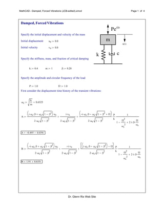
- 1. MathCAD - Damped, Forced Vibrations (JCB-edited).xmcd Page 1 of 4 m k c Pei t ( )u t Damped, Forced Vibrations Specify the initial displacement and velocity of the mass Initial displacement u0 0.0 Initial velocity v0 0.0 Specify the stiffness, mass, and fraction of critical damping k 0.4 m 1 β 0.20 Specify the amplitude and circular frequency of the load P 1.0 Ω 1.0 First consider the displacement time history of the transient vibrations: ωn k m 0.6325 A i ωn β ωn 1 β 2 u0 2 ωn 1 β 2 i v0 2 ωn 1 β 2 i ωn β ωn 1 β 2 Ω 2 ωn 1 β 2 P k 1 1 Ω 2 ωn 2 2 i β Ω ωn A 0.495 0.039i B i ωn β ωn 1 β 2 u0 2 ωn 1 β 2 i v0 2 ωn 1 β 2 i ωn β ωn 1 β 2 Ω 2 ωn 1 β 2 P k 1 1 Ω 2 ωn 2 2 i β Ω ωn B 1.91 0.635i Dr. Glenn Rix Web Site
- 2. MathCAD - Damped, Forced Vibrations (JCB-edited).xmcd Page 2 of 4 The constants parameters, A and B can be simplified further which assists us in observing the influence of the different parameter groups. δst P k 2.500 ωd ωn 1 β 2 0.6197 r Ω ωn 1.581 rD ωd ωn Φ 1 1 r 2 2 i β r α 1 2 1 β 2 0.5103 A α rD i β u0 i v0 ωn rD r i β Φ δst 0.495 0.039i B α rD i β u0 i v0 ωn rD r i β Φ δst 1.91 0.635i ut t( ) exp ωn β t A exp i ωd t B exp i ωd t Plot the displacement time history of the transient vibrations t 0 0.1 50 0 5 10 15 20 25 30 35 40 45 50 2 1 1 2 Time Displacement Im ut t( ) t Dr. Glenn Rix Web Site
- 3. MathCAD - Damped, Forced Vibrations (JCB-edited).xmcd Page 3 of 4 Now consider the steady state component of the vibrations which is given by: uss t( ) P k 1 1 Ω 2 ωn 2 2 i β Ω ωn exp i Ω t( ) Let AH Φ δst 1.415 0.597i uss t( ) AH exp i Ω t( ) 0 5 10 15 20 25 30 35 40 45 50 2 1 1 2 Time Displacement Im uss t( ) t Now combine the two displacement components u t( ) Im ut t( ) Im uss t( ) 0 10 20 30 40 50 3 2 1 1 2 3 Time Displacement u t( ) t Dr. Glenn Rix Web Site
- 4. MathCAD - Damped, Forced Vibrations (JCB-edited).xmcd Page 4 of 4 Plot the load and displacement simultaneously p t( ) Im P exp i Ω t( )( ) 0 5 10 15 20 25 30 35 40 45 50 3 2 1 1 2 3 Time Displacement u t( ) p t( ) t Dr. Glenn Rix Web Site