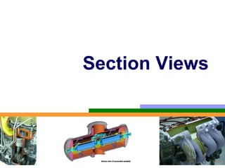
2. PURPOSES OF
SECTION VIEWS
Clarify the views by
reducing or eliminating the hidden lines.
revealing the cross sectional’s shape.
Facilitate the dimensioning.
Let See the
example
5. CUTTING PLANE
Cutting plane is a plane that imaginarily cuts
the object to reveal the internal features.
Cutting
plane Cutting plane line
Section lines
6. CUTTING PLANE LINE
Cutting plane line is an edge view of the cutting
plane.
Indicate the path
of cutting plane.
7. CUTTING PLANE LINESTYLES
Thick line
ANSI
Viewing
standard
direction
Thick line
Viewing
direction
JIS & ISO Thin line
standard
This course Viewing
direction
8. SECTION LINING
Section lines or cross-hatch lines are used to
indicate the surfaces that are cut by the cutting
plane.
Section
lines
Drawn with 4H pencil.
9. SECTION LINES SYMBOLS
The section lines are different for each of
material’s type.
For practical purpose, the cast iron symbol is
used most often for any materials.
Cast iron, Steel Concrete Sand Wood
Malleable iron
10. SECTION LINING PRACTICE
The spaces between lines may vary from 1.5 mm
for small sections to 3 mm for large sections.
COMMON MISTAKE
11. SECTION LINING PRACTICE
It should not be drawn parallel or perpendicular
to contour of the view.
COMMON MISTAKE
14. FULL SECTION VIEW
The view is made by passing the straight cutting
plane completely through the part.
15. Full Sections
In Full Sections,
one-half of the part
is removed.
(Technically, the
cutting plane may be
placed anywhere,
but it should always
be placed where the
most information can
be depicted in the
16. • If the origin of the
Full Sections section view is
A A
obvious to the
reader of the
drawing, the cutting
plane is not
considered
necessary.
• In this case, it is
very clear where the
SECTION A-A
section view
originated, so the
17. OFFSET SECTION VIEW
The view is made by passing the bended cutting
plane completely through the part.
Do not show the edge views
of the cutting plane.
25. TREATMENT OF HIDDEN LINES
Hidden lines are normally omitted from section
views.
26. HALF SECTION VIEW
The view is made by passing the cutting plane halfway
through an object and remove a quarter of it.
27. HALF SECTION VIEW
A center line is used to separate the sectioned half
from the unsectioned half of the view.
Hidden line is omitted in unsection half of the view.
30. BROKEN-OUT SECTION VIEW
The view is made by passing the cutting plane normal
to the viewing direction and removing the portion of an
object in front of it.
31. BROKEN-OUT SECTION VIEW
A break line is used to separate
the sectioned portion from the
unsectioned portion of the view.
Break line is a thin continuous
line (4H) and is drawn freehand.
There is no cutting plane line.
33. REVOLVED SECTION VIEW
Revolved sections show cross-sectional
features of a part.
No need for additional orthographic
views.
This section is especially helpful when a
cross-section varies.
36. REVOLVED SECTION VIEW
Steps in construction
Given
Edge view of
cross-section
Step 1
a. Assign position of cutting plane.
b. Draw axis of rotation in front view.
40. REVOLVED SECTION VIEW
Placement of revolved section
1. Superimposed to orthographic view.
2. Break from orthographic view.
Break Superimposed
41. REVOLVED SECTION VIEW
Placement of revolved section
1. Superimposed to orthographic view.
2. Break from orthographic view.
Break Superimposed
42. REMOVED SECTION VIEW
6. Removed section
Removed section is revolved section.
Section view is shown outside the view.
Used where space does not enough for
revolved section
Can be located elsewhere on a drawing
with properly labeled