Double Revolving field theory-how the rotor develops torque
COMSOL Conference Europe Milan 2012
1. Multiphysics Modeling of Spring-Supported Thrust Bearings for
Hydropower Applications
F. Xavier Borràs*1
, Jan Ukonsaari2
and Andreas Almqvist1
1
Luleå University of Technology, Division of Machine Elements, Luleå, Sweden;
2
Vattenfall, Vattenfall Research and Development AB, Luleå, Sweden.
*Corresponding author: Luleå University of Technology, 97 187 Luleå (Sweden), borrasfx@gmail.com
Abstract: The present work is an attempt in
predicting the performance of spring-supported
thrust bearings. Thorough research has been
done into the existing theories in order to
incorporate them into the COMSOL
Multiphysics software. The results proved the
capability of coupling partial differential
equations (PDE) to form a complex non linear
system and thus obtaining proper results. The
Reynolds equation is solved taking into account
pad and collar elastic deformation and thermal
expansion. The importance of including these
phenomena has been evaluated. Linking the
bearing material properties with the pressure and
temperature developed in the assembly has been
seen to play an important role. The result of this
research is a hydrodynamic model taking into
account the main variables involved in a spring-
supported thrust bearing performance. The
model developed can be used when designing or
modifying thrust bearings.
Keywords: thrust bearings, Reynolds, spring-
supported, elastic deformation, thermal
expansion.
1. Introduction
The main feature of the thrust bearings is to
provide for separation between the shaft and the
support, something essential when working with
hundreds of tones spinning at hundreds of
revolutions per minute. A physical contact
between both surfaces would represent the
destruction of the machine.
A highly pressured, micrometre thin, lubricant
film is located between the collar or runner
(dynamic part) and the pad (static part). The
static piece is compound from a number of
segment shaped pads.
The most common type for hydropower
applications are the tilting pad thrust bearings
(TPTB). In this kind of thrust bearings, each pad
is placed over a spherical pivot that allows tilt to
the surface (Figure 1). A fixed defined pivot
point restricts heavily the degrees of freedom of
the pad.
Figure 1. Tilting pad thrust bearings performance
scheme.
To allow tilting and at the same time avoid
this punctual fixed contact point, the spring-
supported thrust bearings were created. This
second kind of thrust bearings allows working
under a wide range of operating conditions
maintaining a good efficiency. The pads lie on a
spring mattress that handles the applied load.
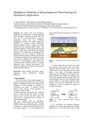
The spring-supported thrust bearings follow the
same principles, however with a different tilting
system (Figure 2). The springs-supported thrust
bearing has good self adjustment and heat
dissipation. It is also of benefit with respect to
vibration in running.
Figure 2. Spring supported thrust bearing
performance.
It is well-known the argument between
tilting-pad and spring-supported thrust bearings
supporters. It is not clear which grants better
Excerpt from the Proceedings of the 2012 COMSOL Conference in Milan
2. results. Although the spring-supported has a not
fix pivot point, the spring pattern hampers
considerably its study.
The complexity of this kind of thrust
bearings is mostly the strong linkage between all
the phenomena involved from different
engineering fields.
2. Model
The study carried out is a
thermoelastohydrodynamic analysis (TEHD)
which requires a high computational capacity to
solve a complex FEM non lineal system (Figure
3).
Figure 3. The three models required to predict spring-
supported thrust bearing performance (pad, fluid film
and collar).
2.1 Pressure Distribution: the Reynolds
Equation
The pressure distribution on the thin
lubricant film is obtained from solving the
Reynolds Equation (Figure 4). The gap is small
enough to use the Reynolds Equation instead of
the general Navier-Stokes equation which would
increase the complexity of the calculations.
The Reynolds Equations in 2D reads:
0
2
1
12
3
hU
h
where ρ is the lubricant density, η is the
viscosity, U is the collar velocity and h is the
geometry of the gap between the pad and the
collar. Lubricant density and viscosity varies
with pressure and temperature and they have
significant influence on system convergence.
However, the parameter that influences
convergence most is h, i.e., the gap morphology,
which encompasses both mechanical
deformation and thermal expansion.
Figure 4. Pressure distribution on the pad surface.
As it is found in many rotor hydraulic
machines, cavitation is a phenomenon to deal
with when working with thrust bearings. Due to
the divergent shape of some parts of the gap,
huge negative pressure regions can be found
when solving the Reynolds Equation. In the
present model, the effect of cavitation is
accounted for by simply using the positive part
of the pressure distribution while integrating load
carrying capacity.
2.2 Elastic Deformation
The pressure distribution in the fluid film is
applied in the boundary conditions on the other
models (pad, collar plate and lubricant film).
Here, the pad is modeled as a union of three
different domains: a steel structure, the Babbitt
layer and the foundation of springs. The
materials of the pad and the Babbitt are specific
for each thrust bearing and must be obtained
from the manufacturer. In the present model, the
springs are modeled as elastic cylinders with
corresponding Young modulus and Poisson ratio
adapted to actual spring data. The collar,
normally made from a different material than the
pad, has been also modeled here, with the fluid
pressure contributing towards mechanical
deformation and with convection & conduction
contributing towards thermal expansion. Figure
Excerpt from the Proceedings of the 2012 COMSOL Conference in Milan
3. 5, depicts the total displacement, i.e. both
mechanical deformation and thermal expansion,
at a typical operating point.
Figure 5. Collar deformation due to the pressure
applied and the thermal expansion.
Notice that the displacement of the walls of
the pad and the collar, changes the gap geometry
h defined in the Reynolds Equation. This
coupling substantially increases the non-linearity
of the problem.
2.3 Temperature Distribution
The temperature plays an important role for
the performance of the bearing. It is essential to
take into account the thermal expansion of the
solid geometries and the lubricant material
proprieties variation with temperature; mainly
the density and the viscosity of the fluid.
The temperature distribution in the fluid film
is obtained from the definition of a Heat Transfer
in Fluids physic in the fluid model (Figure 6):
y
p
v
x
p
u
T
p
T
z
v
z
u
z
T
k
y
T
v
x
T
uCp
ff
ff
ff
22
2
2
As explained, the pressure on the gap is
obtained from solving the Reynolds Equation
defined on the pad surface. The fluid velocity
field u=u(x,y,z), is also deduced from the
pressure distribution;
p
z
u
2
2
The temperature of the lubricant film governs
the temperature of the whole assembly since the
viscous heating is the only heat source included
in the present study. The temperature in each
node contributes to the thermal expansion of the
pad and the collar.
Figure 6. Temperature distribution of the fluid film.
3. Use of COMSOL Multiphysics
The most important governing equation
defined in the current study is the Reynolds
Equation. The equation is specified in the
Lubricant Shell physics which is defined on the
pad surface. A null boundary pressure is stated
since this is a hydrodynamic approach. The
velocity field of the moving walls it deduced
from the angular velocity of the turbine and
decomposed trigonometrically. The angular
speed is left as an input parameter.
Another input parameter when working with
turbines is the external load to handle (shaft and
water weight). A global equation modeling the
force balance between the generated pressure
and the external load is introduced i.e.;
extfluid WFpdS
Equality of this condition is reached by
varying the average distance between the pad
Excerpt from the Proceedings of the 2012 COMSOL Conference in Milan
4. and the collar. This is achieved by means of the
Lubricant Shell physics.
A Solid Mechanics physics is defined on the
whole pad geometry. The pressure obtained from
solving the Reynolds Equation is used as
boundary load. A rigid surface is used to model
the support for the elastic cylinders, modeling
the spring foundation, so that it’s movement is
restricted.
The last physics required for this spring-
supported thrust bearing model, is the Heat
Transfer in Solids physics. The temperature
distribution of the top surface of the pad is
obtained by solving the Energy Equation in the
fluid model. On the other boundaries, convective
cooling is imposed to take into account the heat
transferred from the pad to the lubricant bath. In
this way the temperature distribution in the solid
is obtained, which in turn makes it possible to
estimate the thermal expansion in the Solid
Mechanic physics. Figure 7, shows the
temperature of the pad.
Figure 7. Temperature distribution of the pad.
The collar plate model follows the same
principles as the pad. A Solid Mechanics physics
is defined in which the fluid pressure acts as
boundary load and the collar’s top surface is
modeled as fixed.
A Heat Transfer in Solids physics is also
defined in this model to obtain the temperature
distribution in the collar and then estimate its
thermal expansion. A uniform temperature is
considered on the lower surface of the pad, due
to its moving nature. It is considered the heat
flux transferred from the fluid through the shaft.
The displacement field obtained from the pad
and collar model confers precisely the gap
geometry (Figure 8). Both displacements fields
are included in the gap definition on the
Lubricant Shell physics.
Figure 8. Fluid film thickness results from the
combination of the pad and collar surfaces
deformation.
A fluid model was necessary to consider the
temperature increment. The Energy Equation is
defined in the whole fluid domain. The velocity
field can be deduced from the pressure
distribution obtained in the Lubricant Shell. The
heat source is determined from the shear stress
suffered in the fluid film. In order to match the
geometry of this model with the gap geometry, a
Moving Mesh is defined in this geometry. The
displacements of this mesh are obtained from the
displacement fields of the pad and collar models.
It has been necessary to define extrusion model
coupling operators to use the different fields
obtained in a model into another one.
4. Results
The final model is capable to combine the
pad and runner displacement fields defining
ideally the final gap morphology. These
displacement fields from the solid compounds
take into account the deflection suffered from the
pressure applied and its counteraction by the
thermal expansion. A large effort was spent to
model the gap geometry due to its significance
when solving the Reynolds equation. The model
estimates also the temperature distribution,
which depend on the bath temperature, the shaft
rotational velocity, the external load applied and
the bearing design. The model has been designed
for pure hydrodynamic conditions; no
Excerpt from the Proceedings of the 2012 COMSOL Conference in Milan
5. hydrostatic elements have been input. The
material proprieties, as confirmed by the
simulations, play an important role. The model
developed allows predicting e.g. overload
situations, see Figure 9, test different kinds of
lubricants, see Figure 10, or test the influence of
different spring’s distributions.
Figure 9. Variation of the film thickness and the pad
temperature with external load.
Figure 10. Comparison of a) film thickness, and b)
pad temperature along the midline of the pad when
using two different lubricants (ISO VG68, ISO
VG32).
7. Conclusions
A model for spring-supported thrust bearings
simulations has been developed. The true
multiphysics model, efficiently couples the fluid
flow, the fluid-solid interaction and the
convection and conduction occurring within a
typical spring-supported thrust bearing.
With special attention paid to applicability,
the model was implemented in order to be easily
adapted to a wide large class spring-supported
thrust bearings. It allows for testing different
lubricants, loads and speeds in order to predict
the consequences of changing these. The model
developed can be used to facilitate designing or
modifying thrust bearings. It is also gives a
better understating of the behaviour of this type
of bearings.
8. References
1. J. H. Vohr, Prediction of operating
temperature of thrust bearings, ASME, 103, 97-
106 (1981)
2. C. M. Ettles, Three dimensional computation
of thrust bearings, Tribology Series, 11, 95-104
(1987)
3. A. L. Brown, J. H. Ferguson and J. B. Medley,
Spring-supported thrust bearings for
Hydroelectric generators: Finite element analysis
of pad deflection, Tribology Series, 39, 99-110
(2001)
4. D. Markin, D. M. C. McCarthy and S. B.
Glavatskih, A FEM approach to simulation of
tilting-pad thrust bearing assemblies, Tribology
International, (2003)
5. R. A. Boudry, E. C. Khun and W. W. Wise,
Influence of load and thermal distortion on
the design of large thrust bearings, Trans ASME,
80, 807-818 (1958)
6. F. X. Borràs, A. Almqvist, J. Ukonsaari,
Multiphysics Modelling of Spring-Supported
Thrust Bearings for Hydropower Applications,
LTU Publications (2012).
9. Acknowledgements
This project would not have been possible
without the help from Patrick Issakson, Ivar
Kjelberg and Fredrik Nääs.
b)
a)
0%
100%
50%
0%
100%
50%
Excerpt from the Proceedings of the 2012 COMSOL Conference in Milan