1. ON-SITE HYDROGEN PRODUCTION AND ITS USE IN
INTERNAL COMBUSTION ENGINE
BACKGROUND OF THE INVENTION:
The field of the present invention relates with the application and producing hydrogen gas from
waste aluminium with water and catalyst sodium hydroxide to meet the demand and supply for
any load instead of storing at high pressure.
It has been proposed to replace conventional Hydrogen generation units which are specifically
made for scientific purpose and tedious for the use of laymen. The present invention is made from
such a background in which hydrogen gas is used to produce power which can be easily used in
remote areas.
The inventors of this invention have found a way to minimize the safety issues by eliminating high
pressure hydrogen cylinders and generation of hydrogen as per demand of the load.
There are so many systems commercially available for hydrogen generation and their application,
but this invention comprises of both the hydrogen generation and its use as a fuel in IC engines.
SUMMERY OF THE INVENTION:
Accordingly the object of this invention is to provide a safe method to use hydrogen for generating
power.
The present situation of using hydrogen as a fuel is very limited due to its high pressure storage
problem. This invention offers the hydrogen generation from aluminium reacting with water in the
presence of catalyst sodium hydroxide in a reaction chamber. The gas is further filtered and used
in an internal combustion engine to generate power.
The method and apparatus according to the present invention offers a practical process and a safe
device for use by the general public to generate power, electricity and heat in power outage
situation or in remote location where electricity is not available. Furthermore, the invention uses
aluminium waste readily available in domestic garbage and metal working shops, to promote
recycling and energy conservation.
2. ON-SITE HYDROGEN PRODUCTION AND ITS USE IN
INTERNAL COMBUSTION ENGINE
DETAILED DESCRIPTION OF THE PREFERRED EMBODIMENT
The apparatus and method of this invention rapidly generates useful heat energy and hydrogen gas
from reactants that are very safe to store.
While this invention is susceptible of embodiments in many different forms there is shown in the
drawings and will be described in details herein a specific embodiment of the method and
apparatus according to the present invention, with the understanding that the present disclosure is
to be considered as an example of the principles of the invention and is not intended to limit the
invention to the embodiment illustrated.
The production of hydrogen and its use according to the present invention is obtained by a catalytic
reaction of aluminium with water. The reaction produces a large amount of heat and hydrogen gas.
The preferred catalyst is sodium hydroxide (NaOH).
Our invention relates to an attitude insensitive generator for producing gas by contact of a liquid
reactant with a solid body providing a reaction surface.
The issues related to cost and storage of hydrogen in current technology shows need of a simple
and cheap system for hydrogen production that can be used to produce hydrogen on demand
continuously so that hydrogen doesn’t have to be stored and transported.
We are introducing a new aluminum-based hydrogen generation system that uses aluminum and
sodium hydroxide solution as its fuel. This reaction produces hydrogen at a higher rates that are
enough to satisfy the different load conditions of engine. This system will produce and supply
hydrogen to the engine according to the need of the engine and hence eliminating the problem of
hydrogen storage.
We are introducing a system for reacting scrap aluminum with sodium hydroxide solution at
specific concentration to produce large amount of hydrogen along with sodium aluminate as by-
product. The system exhibits a favorable combination of high hydrogen generation rate and rapid
response of chemical reaction which makes it promising for portable hydrogen source application.
The reaction to be carried out between sodium and aluminum in a closed chamber is given below.
Aluminum + Sodium Hydroxide → Hydrogen + Sodium Aluminate
2Al (s) + 6NaOH (aq) → 3H2 (g) + 2Na3AlO3 (aq)
Having explained the preferred method for producing hydrogen gas, the following disclosure and
drawing describes a preferred apparatus for carrying out the method.
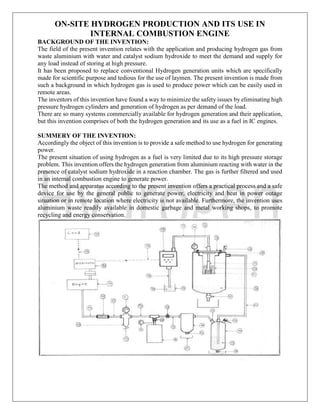
Referring firstly to FIGS. 1, energy production apparatus according to the preferred embodiment
of the present invention is illustrated therein. The energy production apparatus, also referred to
herein as the reaction chamber 42 is illustrated in these figures in it’s entirely. The reaction
chamber 42 uses water and waste aluminium as fuel and sodium hydroxide (NaOH) or caustic
soda as a catalyst and surface conditioner to reduce the formation of oxide layers on the aluminium
particles.
The system is designed in such a way that there is no need of human control after all the possible
settings are made. The invention is about generating power by burning hydrogen fuel in a safe and
easy way herein FIG. 1 is clearly explained in the schematic diagram which consists of the reaction
chamber 42 as described in FIG. 2. The reaction chamber 42 which is a pressure vessel made with
material SS316 in order to sustain high temperature, pressure, hydrogen embrittlement and vigor
of the reaction.
3. ON-SITE HYDROGEN PRODUCTION AND ITS USE IN
INTERNAL COMBUSTION ENGINE
The reaction chamber 42 is well equipped with the safety devices like spring loaded safety valve
12 which is pre settled at 6 bar pressure so as to maintain the stable pressure in the system and a
pressure gauge 14. The reaction chamber 42 is designed in such a way that it will ensure complete
reaction, as described in FIG 2 a reaction chamber has an inbuilt collar to support a cartridge 10
made of SS316. Cartridge 10 has holes 51 at bottom surface to release the byproducts in bottom
of reaction chamber 42. Inside cartridge rests a perforated core structure 11 which enables even
distribution of sodium hydroxide and water with aluminium. The core structure 11 is cylindrical
and pyramidal in shape mounted over a cylinder made up of perforated net of SS316. Top lid 13
is used to close the reaction chamber. The said top lid 13 has an opening in which a non-return
valve 16 is used which prevents the back pressure of hydrogen gas to dozing pump 43.
Gas tubing 20 connects reaction chamber 42 to the aqueous flash filter 44 which is designed for
the safety from back fire as well as it filters the gas produced from reaction chamber 42 which is
having unreacted aluminium particles or vigor from the reaction. The filtration process consist of
one inlet pipe 23 which is submersed in tap water 41 and one outlet 24 for releasing gas to the
outlet pipe 24. The aqueous flash filter also have two valves 21 and 22 for regularly replacing the
water 41.
After the filtration from aqueous flash filter 44 a moisture separator 45 is connected to the gas
outlet tube 24, the moisture separator 45 is used to remove all the moisture contained from the gas
during reaction or aqueous filtration. The moisture separator 45 has a drain valve 52 and a drain
sump 26 which is used to periodic drain of the condensed moisture trapped in moisture separator
45.
The moisture separator is further connected with an accumulator 46 connected from tube 25 with
a ball valve 27. The accumulator 46 is a device which is designed to govern and maintained a load
by accumulating the gas at system pressure. The accumulator 46 also has a pressure gauge 29 and
a ball valve 28 which is used to operate accumulator 46. The gas is now connected to a pressure
compensating valve 47 with the tubing 30. The pressure compensating valve 47 also have a
pressure gauge 31 to represent the outlet pressure and an adjustable screw 32 is used to set the
outlet pressure irrespective to the inlet pressure. The pressure compensating valve 47 is selected
with such a mechanism comprising of spring loaded diaphragm to control the outlet flow of the
gas. In any conventional pressure regulating valve only pressure can be controlled but if inlet
pressure increases the flow rate also changes accordingly but to drive system it is very important
to maintain a consistent flow rate.
An additional device is also incorporated in the system which is very essential to prevent safety of
this invention. A main drawback of using hydrogen gas as a fuel in an internal combustion engine
is its backfire which is faster than any gas due to the flame speed of hydrogen combustion and its
property to burn in wide range of air fuel ratio, so as to prevent backfire a dry honeycomb fire
arrestor 48 is connected from tubing 33. Fire arrestor have a honeycomb structure which doesn’t
allow flame to travel through it. Outlet of fire arrestor 48 is connected to carburetor of engine 49
through tubing 34.
Specific changes are made during this invention regarding the air-fuel ratio in the carburetor for
hydrogen gas as fuel. The internal combustion engine 49 is a (76) cc engine basically operated on
gasoline and kerosene which is modified for the use of hydrogen gas.
An alternator 50 or an electricity generator is coupled with the engine 49 propelled from hydrogen
gas, the alternator 50 is having the capacity of 0.650 Kw. The power generated is 230V AC which
is enough to sustain the applied load and run dosing pump.
4. ON-SITE HYDROGEN PRODUCTION AND ITS USE IN
INTERNAL COMBUSTION ENGINE
FLOW OF SYSTEM
To start the system ball valve 29 is opened and valve 27 is kept closed the gas in accumulator 46
is supplied to engine 49 through pressure compensator 47 and fire arrestor 48.
Engine 49 runs alternator 50 and produces power in form of electricity. Said electricity is used to
run dozing pump 43. Dozing pump 43 sucks sodium hydroxide solution from tubing 18 stored in
container 19 and delivers it to perforated core 11 which is in Said Cartridge 10 which is filled with
said waste aluminium acting as fuel.
Feed rate of said sodium hydroxide solution can be adjusted by regulator of dozing pump 43.
Hydrogen is produced in the reaction chamber 42 by the reaction of said solution and aluminium
present in cartridge 10. By product of said reaction that is sodium aluminate is drained out of
cartridge through holes 51.
Gas produced in said reaction is supplied to aqueous flash filter 44 through tubing 20 here any
residuals in the gas are separated out as gas passes through water in said aqueous flash filter 44.
Further gas is supplied to moisture separator 45 through tubing 24. In water separator 45 the gas
is dried by passing through water absorbent material. Absorbed water can be drained out by
opening ball valve 52 in drain sump 26.
When system pressure is built up to pressure of 4 bar ball valve 27 is opened manually and system
starts running on the gas produced in reaction chamber 42. Now load 37 on the alternator 50 can
be switched on and can be used for variety of purposes. This load also includes power supply for
the said dosing pump 43. The innovation only runs on the power which is already generated in the
system by the said fuel. So the system is itself sufficient to generate power.
The present embodiment is safe to use with all the said safety equipment and gives the output as
usable power source.
The inventors of this invention believes that the invention in not bounded with any kind of limits,
in spite it can be used in and for several type of applications which includes heat generation, power
generation using internal combustion engine, electricity generation by coupling alternator with
internal combustion engine, electricity production by using hydrogen gas in fuel cell and many
more.
The inventors see their invention for not only specific but to use it in a commercial way where
using scrap aluminium which also promotes recycling.