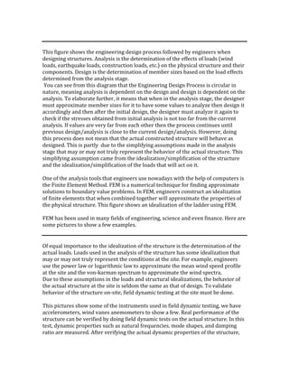
1. This figure shows the engineering design process followed by engineers when
designing structures. Analysis is the determination of the effects of loads (wind
loads, earthquake loads, construction loads, etc.) on the physical structure and their
components. Design is the determination of member sizes based on the load effects
determined from the analysis stage.
You can see from this diagram that the Engineering Design Process is circular in
nature, meaning analysis is dependent on the design and design is dependent on the
analysis. To elaborate further, it means that when in the analysis stage, the designer
must approximate member sizes for it to have some values to analyze then design it
accordingly and then after the initial design, the designer must analyze it again to
check if the stresses obtained from initial analysis is not too far from the current
analysis. If values are very far from each other then the process continues until
previous design/analysis is close to the current design/analysis. However, doing
this process does not mean that the actual constructed structure will behave as
designed. This is partly due to the simplifying assumptions made in the analysis
stage that may or may not truly represent the behavior of the actual structure. This
simplifying assumption came from the idealization/simplification of the structure
and the idealization/simplification of the loads that will act on it.
One of the analysis tools that engineers use nowadays with the help of computers is
the Finite Element Method. FEM is a numerical technique for finding approximate
solutions to boundary value problems. In FEM, engineers construct an idealization
of finite elements that when combined together will approximate the properties of
the physical structure. This figure shows an idealization of the ladder using FEM.
FEM has been used in many fields of engineering, science and even finance. Here are
some pictures to show a few examples.
Of equal importance to the idealization of the structure is the determination of the
actual loads. Loads used in the analysis of the structure has some idealization that
may or may not truly represent the conditions at the site. For example, engineers
use the power law or logarithmic law to approximate the mean wind speed profile
at the site and the von-karman spectrum to approximate the wind spectra.
Due to these assumptions in the loads and structural idealizations, the behavior of
the actual structure at the site is seldom the same as that of design. To validate
behavior of the structure on-site, field dynamic testing at the site must be done.
This pictures show some of the instruments used in field dynamic testing, we have
accelerometers, wind vanes anemometers to show a few. Real performance of the
structure can be verified by doing field dynamic tests on the actual structure. In this
test, dynamic properties such as natural frequencies, mode shapes, and damping
ratio are measured. After verifying the actual dynamic properties of the structure,
2. the analytical model used in the design can now be modified to tune it with the
properties measured from the field. This is known as the Finite Element Model
Updating.
Finite Element Model Updating has been used by many researchers and here are
some examples to name a few,…
… These researches show the applicability of the Finite Element Model Updating
Procedure to bridges. In the Philippines, the one special type of structure of most
interest to engineers are the billboards.
A bilboard is a large outdoor advertising structure typically found in high traffic
areas such as alongside busy roads. These pictures show some example of billboards
in the Philippines.
Since our country is a typical pathway of tropical cyclones, many structures
including billboards in the country topple. Some example are shown in this slide.
Due to this problems with billboards, we want to conduct a research with the
objective …