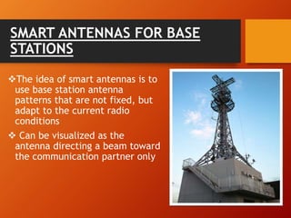
1) Smart antennas use antenna arrays that can change their radiation patterns in response to the signal environment to improve wireless system performance.
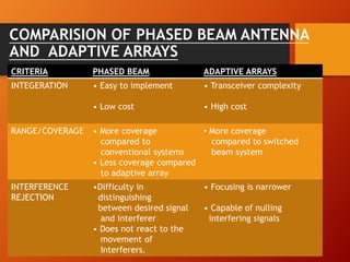
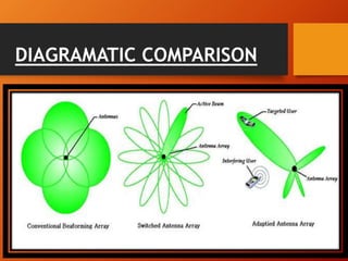
2) There are two main types of smart antennas: phased beam antennas which form a finite number of fixed patterns, and adaptive array antennas which can form an infinite number of patterns.
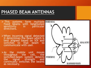
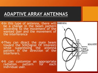
3) Adaptive array antennas can direct their main beam toward the desired signal while suppressing interference by adapting their pattern, allowing them to customize coverage for each user.