1. HP4500TECHDRUM
Technical Instructions Printers OEM Info Tools 1
HP4500/4550 Part Number: C4195A #1 Phillips Head Screwdriver
CORPORATE HP4500N/4550N Yield @ 5%: 25,000 Black Small Flat Blade Screwdriver
LOS ANGELES, USA 6,250 Color Needlenose Pliers
HP4500DN/4550DN Anhydrous Isopropyl Alcohol
US 1 800 394.9900 Pages/Min.: 4 Color/16 Black
Int’l +1 818 837.8100 Padding Powder
FAX 1 800 394.9910 Resolution: 600dpi
Soft Lint-Free Cloth
Int’l +1 818 838.7047 (HP ImageRET 2400)
Cotton Swabs
ATLANTA, USA Vacuum or Compressed Air
US 1 877 676.4223
Int’l +1 770 516.9488
FAX 1 877 337.7976
Int’l +1 770 516.7794
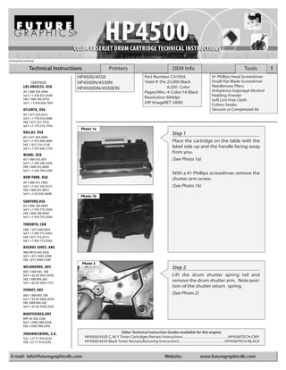
Photo 1a
DALLAS, USA Step 1
US 1 877 499.4989
Int’l +1 972 840.4989 Place the cartridge on the table with the
FAX 1 877 774.1750
Int’l +1 972 840.1750 label side up and the handle facing away
from you.
MIAMI, USA
US 1 800 595.429 (See Photo 1a)
Int’l +1 305 594.3396
FAX 1 800 522.8640
Int’l +1 305 594.3309
With a #1 Phillips screwdriver, remove the
NEW YORK, USA shutter arm screw.
US 1 800 431.7884
Int’l +1 631 345.0121 (See Photo 1b)
FAX 1 800 431.8812
Int’l +1 631345.0690
Photo 1b
SANFORD,USA
US 1 800 786.9049
Int’l +1 919 775.4584
FAX 1 800 786.9049
Int’l +1 919 775.4584
TORONTO, CAN
CAN 1 877 848.0818
Int’l +1 905 712.9501
FAX 1 877 772.6773
Int’l +1 905 712.9502
BUENOS AIRES, ARG
ARG 0810 444.2656
Int’l +011 4583.5900
FAX +011 4584.3100
Photo 2
MELBOURNE, AUS Step 2
AUS 1 800 003. 100
Int’l +62 03 9561.8102 Lift the drum shutter spring tail and
FAX 1 800 004.302 remove the drum shutter arm. Note posi-
Int’l +62 03 9561-7751
tion of the shutter return spring.
SYDNEY, AUS
AUS 1 800 003.100
(See Photo 2)
Int’l +62 02 9648.2630
FAX 1800 004.302
Int’l +62 02 9548.2635
MONTEVIDEO,URY
URY 02 902.7206
Int’l +5982 900.8358
FAX +5982 908.3816
JOHANNESBURG, S.A. Other Technical Instruction Guides available for this engine:
S.A. +27 11 974.6155 HP4500/4550 C, M, Y Toner Cartridges Reman. Instructions . . . . . . . . . . . . . . . . . . . . . . . . . . . HP4500TECH-CMY
FAX +27 11 974.3593 HP4500/4550 Black Toner Remanufacturing Instructions . . . . . . . . . . . . . . . . . . . . . . . . . . . HP4500TECH-BLACK
E-mail: info@futuregraphicsllc.com Website: www.futuregraphicsllc.com
2. 2 HP4500 Technical Instructions
Photo 3a
Step 3
Slide the shutter wire out on each side
and set aside for now.
Notes (See Photo 3a and 3b)
Photo 3b
Photo 4
Step 4
Remove the seven (7) Phillips head
screws from the left side plate.
(See Photo 4)
Photo 5
Step 5
Pull off the blue knob on the end of the
drum shaft.
(See Photo 5)
Photo 6
Step 6
Turn the cartridge and remove the six (6)
phillips head screws from the right side
plate .
(See Photo 6)
Need trust-worthy, detailed Technical
Instructions for another engine?
Visit: www.futuregraphicsllc.com
3. HP4500 Technical Instructions 3
Photo 7
Step 7
Carefully remove the right-side plate.
(See Photo 7) Notes
Photo 8
Step 8
With the assembly inverted, remove the
left side plate while balancing the drum
in its normal position.
(See Photo 8)
Photo 9
Step 9
Remove the drum.
(See Photo 9)
Photo 10
Step 10
Remove the PCR cover by inserting a flat
blade screwdriver in the center slot and
release the latch.
(See Photo 10)
Need help with a particular remanu-
facturing problem?
Call the Technical Resource Center from
8am - 5pm PST: 800 394.9900
4. 4 HP4500 Technical Instructions
Photo 11
Step11
Remove the PCR, wipe clean with a soft,
dry cloth and set aside.
Notes (See Photo 11)
Photo 12
Step12
Remove the two Phillips head machine
screws holding the wiper blade in posi-
tion.
(See Photo 12)
Photo 13a
Step 13
Note the stabilizer bar attached to the
wiper blade with two (2) long shouldered
screws.
(See Photo13a)
The stabilizer bar must be moved to the
new wiper blade. Note the correct posi-
Photo 13b
tion before removing it from the used
part. Apply the adhesive strip to the sta-
bilizer bar and carefully affix to the new
blade. Anchor with two (2) screws.
(See Photo13b)
Photo 14
Step 14
Remove the chip housing located on the
left side of the cartridge by removing the
two Phillips head screws from the brack-
et.
(See Photo 14)
Photo 15
Step 15
Replace the chip with a new one by pry-
ing up on the old one to extract it. Press a
new chip into position. Follow the
detailed instruction printed on the
replacement chip label.
NOTE: Used chips can be sent into Future
Need trust-worthy, detailed Technical
Graphics to be reset.
Instructions for another engine?
Visit: www.futuregraphicsllc.com (See Photo 15)
5. HP4500 Technical Instructions 5
Photo 16
Step 16
Note the position of the auger gears.
Remove the nine gears from the side of
the cartridge.
Notes
(See Photo 16)
Photo 17
Step 17
Using dry, compressed air, blow out the
waste toner through the auger gear
holes.
(See Photo 17)
NOTE: It is very important to get all the
toner out of the waste unit. Failure to do
so may result in a premature “Drum Life
Low” or “Drum Life Out” error message.
Step 18
Reinstall the waste hopper gears.
Step 19
Reinstall the chip housing with the two (2) Phillips head screws.
Photo 20
Step 20
Inspect the mylar recovery blade for dam-
age, kinks, or waves. Replace if necessary.
(See Photo 20)
Photo 21
Step 21
Install wiper blade assembly and adjust
the position with a blade spacing tool.
(See Photo 21)
Need help with a particular remanu-
Step 22 facturing problem?
Reinstall the cleaned replacement PCR. Call the Technical Resource Center from
8am - 5pm PST: 800 394.9900
6. 6 HP4500 Technical Instructions
Photo 23a
Step 23
Put the padding powder on wiper blade
Notes and drum.
(See Photo 23a)
Install drum left and right side and rotate
the drum toward the wiper blade while
wiping off any powder from the PCR.
Continue turning and wiping until the
PCR is free of any powder.
(See Photo 23b)
Photo 23b
Step 24
Finish assembly in reverse order of disassembly.
Future Graphics (FG) is a distributor of compatible replacement parts and products for imagining equipment.
None of FG's products are genuine OEM replacement parts and no affiliation or sponsorship is to be implied between FG and any OEM.
E-mail: info@futuregraphicsllc.com Website: www.futuregraphicsllc.com