SlideShare a Scribd company logo
1 of 28
UNIT IV FORCED VIBRATION 9
Response of one degree freedom systems to periodic forcing โ€“ Harmonic disturbances โ€“Disturbance
caused by unbalance โ€“ Support motion โ€“transmissibility โ€“ Vibration isolation vibration measurement.
4. Forced Vibration
There is no influence of external forces in the free vibration of a system. Think of a child swinging on
a swing. A child swinging freely on a swing will do so consistently. It consistently takes two to three
seconds to a complete each cycle of swinging. Think of an oscillating pendulum. The vibration of a
pendulum needs no external force to vibrate. A machine left to vibrate freely will tend to vibrate at its
natural oscillation (vibration) rate.
In forced vibration of a system, it is under the influence of external force applied on the system.
The vibration of a machine like a drill is forced vibration. It needs an external force to vibrate.
External forcesare appliedforces. Anappliedforce isaforce that isappliedtoan objectbya personor
anotherobject.If a personispushinga deskacrossthe room, thenthere isan appliedforce actingupon
the object.The appliedforce isthe force exertedonthe deskbythe person. Similarlythe force applied
by the wavesonthe boat.
A boat anchored in a bay is subjected to repeated waves slapping on the sides of the boat. The boat
rocks as long as the waves continue to act on the boat.
Most machine vibrations are also similar. The vibrations are due to repeating forces acting
on its components.
Repeating (Periodic!) forces in machines are mostly due to the rotation of imbalanced (uneven
rotor, bent shaft), misaligned (improper mounting, distortion due to fastening torque), worn
(worn belt, gear teeth), or improperly driven (intermittent bush contact in motors, misfiring
in IC engine cylinder, uneven air supply) machine components.
4.1 Types of forces causing vibration
Types of forces (forcing function!) that cause vibration are:
1. Random forcing
2. Impulsive forcing
3. Periodic forcing
1. Random forcing:
These are unpredictable and non-deterministic (difficult to determine the magnitude using
expression)
Examples: Ground motion during earth quake, jet engine noise.
2. Impulsive forcing: They are short duration forces and non-periodic. The vibrations die out soon
and are not significant.
Examples: Rock explosion, gun firing, punching die.
3. Periodic forcing: These are predictable and deterministic (magnitude given by an expression).
Example: Centrifugal (unbalanced) forces caused by an eccentric rotating mass, Inertia
(unbalanced) forces caused by reciprocating mass in an IC engine.
4.1.1 Types of forced vibrations
Classifications based on forces causing vibration
I. Forced vibrations are classified according to the type of forces causing the excitation:
1. Random vibration
2. Transient vibration
3. Steady state vibration
1. Random vibration:
Vibrations caused by random forces are called random vibration.
Examples: Ground motion during earth quake, jet engine noise.
2. Transient vibration:
Vibrations caused by impulsive forces and which are of short duration are called transient
vibration.
Examples: Rock explosion, gun firing, punching die.
3. Steady state vibration:
Periodic vibration with constant amplitude is called steady state vibration.
Example: Centrifugal (unbalanced) forces caused by an eccentric rotating mass under steady
state, Inertia (unbalanced) forces caused by reciprocating mass in an IC engine under steady
state.
II. Classifications based on damping resistance
Forced vibrations are also classified into two types based on the existence of damping
resistance:
1. Undamped forced vibration (c = 0)
2. Damped forced vibration (c โ‰  0)
where โ€˜cโ€™ is damping coefficient N/(m/s)
1. Undamped forced vibration (c = 0):
When the damping resistance is nil in a forced vibration, it is called undamped forced vibration.
2. Damped forced vibration (c โ‰  0):
When the damping resistance is present in a forced vibration, it is called damped forced
vibration.
4.2 Periodic forcing
A force which acts continuously at specific intervals of time is called periodic force. There are two
types of periodic forcing:
1. Harmonic forcing and
2. Non-harmonic forcing.
1. Harmonic forcing: When the applied load (force!) varies as a sine or cosine function, it is called
harmonic forcing.
Example:
Sine loading: f(t) = F sin (ฯ‰t)
Cosine loading: f(t) = F cos(ฯ‰t)
The response of a system to a harmonic excitation (loading!) is called harmonic response.
2. Non-harmonic forcing: . Any harmonicfunction such as sin or cosine is periodic.But the converse
is nottrue. Non-harmonic forcing is a type of periodic function that is discontinuous. The restoring
force is independent of displacement. It can be represented by either a discrete or combination
of sin and cos functions.
Example: F(t+tp) = F(t) where t is time, tp is time period
4.2.1 Response to periodic forcing
Forces acting on any vibrating machine systemcan be represented in mathematical equation
๐‘š๐‘ฅฬˆ + ๐‘˜๐‘ฅ = ๐‘˜ ๐‘ฆ( ๐œ”๐‘ก)
๐‘คโ„Ž๐‘’๐‘Ÿ๐‘’ ๐œ”๐‘ก = ๐‘›๐œ‹, ๐‘› ๐‘–๐‘  ๐‘Ž๐‘› ๐‘–๐‘›๐‘ก๐‘’๐‘”๐‘’๐‘Ÿ.
Consider a system as shown in Fig.14.5.1
A roller is guided in the groove of a face cam generates motion from the point O.
It is a single degree of freedom system
The displacement is expressed by the relation
๐‘ฆ( ๐œ”๐‘ก) = ๐œ”0(1 โˆ’ cos ๐œ”๐‘ก)
The far end of the spring of stiffness โ€˜kโ€™ connected to the sliding mass โ€˜mโ€™ is assumed as zero.
The roller is assumed to be in its extreme left position when the cam begins zero.
[Note: By appropriately choosing the initial zero position (A), we can also express the
displacement by the relation ๐‘ฆ ๐ด( ๐œ”๐‘ก) = ๐‘ฆ0 sin ๐œ”๐‘ก ]
The differential equation of motion is now
๐‘š๐‘ฅฬˆ + ๐‘˜๐‘ฅ = ๐‘˜๐œ”0(1 โˆ’ cos ๐œ”๐‘ก)
The solution of this differential equation is
๐‘ฅ = ๐ด cos ๐œ” ๐‘› ๐‘ก + ๐ต sin ๐œ” ๐‘› ๐‘ก + ๐‘ฆ0 [1 โˆ’
cos ๐œ”๐‘ก
1 โˆ’ (
๐œ”
๐œ” ๐‘›
)
2]
Substituting the boundary conditions,
๐‘ฅ(0) = 0, ๐‘ฅฬ‡(0) = 0
๐ด =
(
๐œ”
๐œ” ๐‘›
)
2
๐‘ฆ0
[1 โˆ’ (
๐œ”
๐œ” ๐‘›
)
2
]
๐‘Ž๐‘›๐‘‘ ๐ต = 0
Substituting the coefficient values,
The complete simplified equation of motion is
๐‘ฅ =
(
๐œ”
๐œ” ๐‘›
)
2
๐‘ฆ0 cos ๐œ” ๐‘› ๐‘ก
[1 โˆ’ (
๐œ”
๐œ” ๐‘›
)
2
]
โˆ’
๐‘ฆ0 cos ๐œ”๐‘ก
[1 โˆ’ (
๐œ”
๐œ” ๐‘›
)
2
]
+ ๐‘ฆ0
The total motion contains a constant plus two vibrations of differing amplitudes and
frequencies.
The first term on the right hand side
(
๐œ”
๐œ” ๐‘›
)
2
๐‘ฆ0 cos ๐œ” ๐‘› ๐‘ก
[1 โˆ’ (
๐œ”
๐œ” ๐‘›
)
2
]
is called starting transient. This is not forcing frequency. This is a vibration at natural frequency
ฯ‰n. The presence of friction (damping!) would cause this term to die out after a short period of
time.
๐น๐‘œ๐‘Ÿ
๐œ”
๐œ” ๐‘›
= 0, ๐‘ค๐‘’ ๐‘”๐‘’๐‘ก ๐‘กโ„Ž๐‘’ ๐‘Ÿ๐‘–๐‘”๐‘–๐‘‘ ๐‘๐‘œ๐‘‘๐‘ฆ ๐‘ ๐‘œ๐‘™๐‘ข๐‘ก๐‘–๐‘œ๐‘›
๐‘ฅ = ๐‘ฆ0[1 โˆ’ cos ๐œ”๐‘ก]
If the spring is replaced by a rigid member then k and ฯ‰n become very large. So the mass
exactly follows the cam motion.
4.2.2 Harmonic disturbances
A part of any moving or rotating machinery is often subjected to forces which vary
periodically with respect to time. The parts which are metal elements have both mass and
elasticity. Therefore there is a vibration exists. Since machines normally operate at constant
speeds and constant output, vibratory forces may have a constant amplitude over a period of
time. These varying forces also may vary in magnitude with speed and output. It is general
practice to analyse the vibration problems assuming periodically varying force of constant
amplitude.
4.2.3 Equation of motion
Here we shall consider the application of a single sinusoidal force. The solution contains
components of motion at two frequency levels. One at forcing frequency and the other at
natural frequency of the system.
Since damping is always present in actual systems, component at natural frequency level
becomes insignificant after a certain time.
Therefore the component that contains only forcing frequency remains. This motion is called
steady state motion.
The equation of motion is
๐‘š๐‘ฅฬˆ + ๐‘๐‘ฅฬ‡ + ๐‘˜๐‘ฅ = ๐น0 cos ๐œ”๐‘ก
Complete solution
The complete solution of this equation is
๐‘ฅ = ๐‘’โˆ’๐œ‰๐œ” ๐‘› ๐‘ก( ๐ถ1 sin ๐‘ž๐‘ก + ๐ถ2 cos ๐‘ž๐‘ก) +
๐น0 cos( ๐œ”๐‘ก โˆ’ ๐œ™)
โˆš( ๐‘˜ โˆ’ ๐‘š๐œ”2)2 + ๐‘2 ๐œ”2
(i) Transient response
The first term on the right hand side (RHS) of the complete solution is a transient term. The
exponential part will cause it to decay in a short period of time.
(ii) Steady state response
When the transient part dies out, only the second part remains. Since this is neither the
beginning nor the end, it is called steady state solution.
The following expressions are introduced to obtain simplified solution.
๐ผ๐‘›๐‘’๐‘Ÿ๐‘ก๐‘–๐‘Ž ๐‘“๐‘œ๐‘Ÿ๐‘๐‘’ = ๐‘š๐œ”2
๐‘‹
๐ท๐‘Ž๐‘š๐‘๐‘–๐‘›๐‘” ๐‘“๐‘œ๐‘Ÿ๐‘๐‘’ = ๐‘๐œ”๐‘‹
๐‘†๐‘๐‘Ÿ๐‘–๐‘›๐‘” ๐‘“๐‘œ๐‘Ÿ๐‘๐‘’ = ๐‘˜๐‘‹
๐ธ๐‘ฅ๐‘๐‘–๐‘ก๐‘–๐‘›๐‘” ๐‘“๐‘œ๐‘Ÿ๐‘๐‘’ = ๐น0
๐œ” ๐‘› = โˆš
๐‘˜
๐‘š
๐œ‰ =
๐‘
๐‘ ๐‘
๐‘ ๐‘ = 2๐‘š๐œ” ๐‘›
๐‘‹
(
๐น0
๐‘˜โ„ )
=
1
โˆš(1 โˆ’
๐œ”2
๐œ” ๐‘›
2)
2
+ (2๐œ‰ ๐œ”
๐œ” ๐‘›
โ„ )
2
(
๐น0
๐‘˜โ„ ) = Deflection that a spring of stiffness โ€˜kโ€™ would experience if acted upon by a force ๐น0 .
The plot of frequency response namely Amplitude ratio vs Frequency ratio is shown in Fig.15.6
4.2.4 Dynamic magnifier
Dynamic magnifier (Magnification factor!) is the ratio of maximum displacement of the forced
vibration (amplitude!) to the static deflection due to static force.
๐‘‹ = ๐‘š๐‘Ž๐‘ฅ๐‘–๐‘š๐‘ข๐‘š ๐‘‘๐‘–๐‘ ๐‘๐‘™๐‘Ž๐‘๐‘’๐‘š๐‘’๐‘›๐‘ก ๐‘œ๐‘“ ๐‘“๐‘œ๐‘Ÿ๐‘๐‘’๐‘‘ ๐‘ฃ๐‘–๐‘๐‘Ÿ๐‘Ž๐‘ก๐‘–๐‘œ๐‘›
๐น0
๐‘˜
= ๐‘†๐‘ก๐‘Ž๐‘ก๐‘–๐‘ ๐‘‘๐‘’๐‘“๐‘™๐‘’๐‘๐‘ก๐‘–๐‘œ๐‘›
๐‘‹
(
๐น0
๐‘˜โ„ )
=
1
โˆš(1 โˆ’
๐œ”2
๐œ” ๐‘›
2)
2
+ (2๐œ‰ ๐œ”
๐œ” ๐‘›
โ„ )
2
4.2.5 Frequency response
4.3 Disturbance causedby unbalance
Most of the machines like motors, compressors, engines produce vibrations due to rapid
rotation of a small unbalanced mass.
The differential equation for such systems is
๐‘š๐‘ฅฬˆ + ๐‘˜๐‘ฅ = ๐‘š ๐‘ข ๐‘’ ๐œ”2
cos ๐œ”๐‘ก
๐‘š = ๐‘ฃ๐‘–๐‘๐‘Ÿ๐‘Ž๐‘ก๐‘–๐‘›๐‘” ๐‘š๐‘Ž๐‘ ๐‘ 
๐‘š ๐‘ข = ๐‘ข๐‘›๐‘๐‘Ž๐‘™๐‘Ž๐‘›๐‘๐‘’๐‘‘ ๐‘š๐‘Ž๐‘ ๐‘ 
๐‘’ = ๐‘’๐‘๐‘๐‘’๐‘›๐‘ก๐‘Ÿ๐‘–๐‘๐‘–๐‘ก๐‘ฆ
4.3.1 Rotating unbalance
The following expressions are introduced to obtain simplified solution.
๐‘š = ๐‘ฃ๐‘–๐‘๐‘Ÿ๐‘Ž๐‘ก๐‘–๐‘›๐‘” ๐‘š๐‘Ž๐‘ ๐‘ 
๐‘š ๐‘ข = ๐‘ข๐‘›๐‘๐‘Ž๐‘™๐‘Ž๐‘›๐‘๐‘’๐‘‘ ๐‘š๐‘Ž๐‘ ๐‘ 
๐‘’ = ๐‘’๐‘๐‘๐‘’๐‘›๐‘ก๐‘Ÿ๐‘–๐‘๐‘–๐‘ก๐‘ฆ
The simplified solution is
๐‘‹
( ๐‘š ๐‘ข ๐‘’
๐‘šโ„ )
=
๐œ”2
๐œ” ๐‘›
2
โˆš(1โˆ’
๐œ”2
๐œ” ๐‘›
2)
2
+(2๐œ‰ ๐œ”
๐œ” ๐‘›
โ„ )
2
The plot of frequency response namely Amplitude ratio vs Frequency ratio is shown in Fig.16.2
Fig17.34P589
From the plot we conclude that at high speeds, where the frequency ratio (
๐œ”
๐œ” ๐‘›
)is greater than
unity, amplitude X can be reduced only by reducing the mass and eccentricity of the rotating
unbalance.
Relative motion:
๐‘
๐‘ฆ0
=
๐œ”2
๐œ” ๐‘›
2
โˆš(1 โˆ’
๐œ”2
๐œ” ๐‘›
2)
2
+ (2๐œ‰ ๐œ”
๐œ” ๐‘›
โ„ )
2
4.3.2 Reciprocating unbalance
In a reciprocating engine, there is an unbalanced primary inertia force given by ๐‘š๐œ”2
๐‘Ÿ cos ๐œƒ
This primary unbalanced force always acts along the line of stroke with varying magnitude.
This reciprocating unbalance can be considered as the horizontal component of an imaginary
rotating mass m kept at crank radius r (crank pin!).
Now balancing is done in the same way as we have done for rotating unbalance.
Let the balancing be done by balancing mass mB at radius rB.
The reciprocating unbalance force = Horizontal component of rotating balancing mass
๐‘š๐œ”2
๐‘Ÿ cos ๐œƒ = ๐‘š ๐ต ๐œ”2
๐‘Ÿ๐ต cos ๐œƒ
However the balancing mass also has a vertical component of its centrifugal force namely
๐‘š ๐ต ๐œ”2
๐‘Ÿ๐ต sin ๐œƒ
This remains unbalanced. Therefore when we attempt to balance horizontal component, a
vertical unbalance is introduced!
To minimize the unbalance, a compromise is therefore made. Only a fraction (c ) of the
reciprocating mass is balanced.
๐‘๐‘š๐‘Ÿ = ๐‘š ๐ต ๐‘Ÿ๐ต
If there exists both reciprocating as well as rotating unbalance in a machine, then
๐‘š ๐ต ๐‘Ÿ๐ต = ( ๐‘š ๐‘ข + ๐‘ ๐‘š) ๐‘Ÿ
4.3.3 Damping factor (ฮพ)
Damping factor (damping ratio!) is the ratio of actual damping coefficient, c to critical damping
coefficient, cc.
๐œ‰ =
๐‘
๐‘ ๐‘
๐ผ๐‘“ ๐œ‰ > 1, ๐‘กโ„Ž๐‘’๐‘› ๐‘กโ„Ž๐‘’ ๐‘ ๐‘ฆ๐‘ ๐‘ก๐‘’๐‘š ๐‘–๐‘  ๐‘œ๐‘ฃ๐‘’๐‘Ÿ ๐‘‘๐‘Ž๐‘š๐‘๐‘’๐‘‘.
๐ผ๐‘“ ๐œ‰ = 1, ๐‘กโ„Ž๐‘’๐‘› ๐‘กโ„Ž๐‘’ ๐‘ ๐‘ฆ๐‘ ๐‘ก๐‘’๐‘š ๐‘–๐‘  ๐‘๐‘Ÿ๐‘–๐‘ก๐‘–๐‘๐‘Ž๐‘™๐‘™๐‘ฆ ๐‘‘๐‘Ž๐‘š๐‘๐‘’๐‘‘
๐ผ๐‘“ ๐œ‰ > 1, ๐‘กโ„Ž๐‘’๐‘› ๐‘กโ„Ž๐‘’ ๐‘ ๐‘ฆ๐‘ ๐‘ก๐‘’๐‘š ๐‘–๐‘  ๐‘ข๐‘›๐‘‘๐‘’๐‘Ÿ ๐‘‘๐‘Ž๐‘š๐‘๐‘’๐‘‘
4.3.4 Steady state response
The simplified solution for steady state response X is
๐‘‹
( ๐‘š ๐‘ข ๐‘’
๐‘šโ„ )
=
๐œ”2
๐œ” ๐‘›
2
โˆš(1โˆ’
๐œ”2
๐œ” ๐‘›
2)
2
+(2๐œ‰ ๐œ”
๐œ” ๐‘›
โ„ )
2
4.3.5 Absolute amplitude
The simplified solution for absolute amplitude X is
๐‘‹
( ๐‘š ๐‘ข ๐‘’
๐‘šโ„ )
=
๐œ”2
๐œ” ๐‘›
2
โˆš(1โˆ’
๐œ”2
๐œ” ๐‘›
2)
2
+(2๐œ‰ ๐œ”
๐œ” ๐‘›
โ„ )
2
4.3.6 Relative amplitude
The relative amplitude Z is
From the plot we conclude that at high speeds, where the frequency ratio (
๐œ”
๐œ” ๐‘›
)is greater than
unity, amplitude X can be reduced only by reducing the mass and eccentricity of the rotating
unbalance.
Relative motion:
๐‘
๐‘ฆ0
=
๐œ”2
๐œ” ๐‘›
2
โˆš(1 โˆ’
๐œ”2
๐œ” ๐‘›
2)
2
+ (2๐œ‰ ๐œ”
๐œ” ๐‘›
โ„ )
2
4.3.7 Phase angle
The direction of ๐น0 cos( ๐œ”๐‘ก) will always be ahead of ๐‘˜๐‘‹ cos( ๐œ”๐‘ก โˆ’ ๐œ™) by angle ๐œ™.
The phase angle ๐œ™ is
๐“ = ๐ญ๐š๐งโˆ’๐Ÿ
2๐œ‰ ๐œ”
๐œ” ๐‘›
โ„
(1 โˆ’
๐œ”2
๐œ” ๐‘›
2)
4.3.8 Resultant force on motor
Resultant force on motor is the resultant of the forces exerted by the spring and dashpot
4.3.9 Resonance speed
Let N be the speed of the driving shaft of the motor at which resonance occurs.
The angular speed at which resonance occurs is given by
๐œ” = ๐œ” ๐‘› = โˆš
๐‘˜
๐‘š
Resonance speed N is obtained from the relation
๐œ” =
2๐œ‹๐‘
60
4.3.10 Amplitude of resonance
Amplitude of resonance X is obtained by substituting ๐œ” = ๐œ” ๐‘› in the relation
๐‘‹
( ๐‘š ๐‘ข ๐‘’
๐‘šโ„ )
=
๐œ”2
๐œ” ๐‘›
2
โˆš(1โˆ’
๐œ”2
๐œ” ๐‘›
2)
2
+(2๐œ‰ ๐œ”
๐œ” ๐‘›
โ„ )
2
๐‘‹
(
๐‘š ๐‘ข ๐‘’
๐‘šโ„ )
=
1
โˆš(2๐œ‰ ๐œ”
๐œ” ๐‘›
โ„ )
2
=
1
2๐œ‰ ๐œ”
๐œ” ๐‘›
โ„
๐‘‹
(
๐‘š ๐‘ข ๐‘’
๐‘šโ„ )
=
1
2๐œ‰ ๐œ”
๐œ” ๐‘›
โ„
4.4 Support motion
Support motion is also called base excitation. In many situations, the excitation is created
(applied!) by the base or support configuration. Example: sinusoidal profile of a road.
4.4.1 Absolute amplitude
Absolute harmonic displacement of support is y = Y sin ฯ‰t
Absolute displacement of mass m is x.
Absolute differential equation of motion is
๐‘š๐‘ฅฬˆ + ๐‘๐‘ฅฬ‡ + ๐‘˜๐‘ฅ = ๐‘Œโˆš ๐‘˜2 + ๐‘2 ๐œ”2 sin( ๐œ”๐‘ก + ๐›ผ)
๐‘ญ ๐ŸŽ = ๐’€โˆš ๐’Œ ๐Ÿ + ๐’„ ๐Ÿ ๐Ž ๐Ÿ
4.4.2 Relative amplitude
Relative amplitude is z = y-x, where x is absolute displacement of mass m.
Relative differential equation of motion is
๐‘š๐‘งฬˆ + ๐‘๐‘งฬ‡ + ๐‘˜๐‘ง = ๐‘š๐œ”2
๐‘Œ(sin ๐œ”๐‘ก)
๐น0 = ๐‘š๐œ”2
๐‘Œ
4.4.3 Circular frequency of vibration
Natural circular frequency of motion ๐œ” ๐‘› = โˆš
๐‘˜
๐‘š
๐‘‡๐‘–๐‘š๐‘’ ๐‘๐‘’๐‘Ÿ๐‘–๐‘œ๐‘‘ =
๐‘Š๐‘Ž๐‘ฃ๐‘’ ๐‘™๐‘’๐‘›๐‘”๐‘กโ„Ž
๐‘‰๐‘’๐‘™๐‘œ๐‘๐‘–๐‘ก๐‘ฆ
โ†’ ๐‘ก ๐‘ =
๐œ†
๐‘ฃ
4.4.4 Vertical amplitude of vibration
Steady state amplitude due to excitation of support,
๐‘ฟ =
๐’€โˆš ๐Ÿ+( ๐Ÿ๐ƒ
๐Ž
๐Ž ๐’
)
๐Ÿ
โˆš[ ๐Ÿโˆ’(
๐Ž
๐Ž ๐’
)
๐Ÿ
]
๐Ÿ
+( ๐Ÿ๐ƒ
๐Ž
๐Ž ๐’
)
๐Ÿ
4.5 Vibrationisolation
Vibrations are produced in all machines having motion of unbalanced masses. These vibrations
will be transferred to the foundation or base supports upon which the machines are installed.
This will result in noise, wear, and failure of machine as well as the structure. Hence this is not
desirable and needs to be eliminated (isolated!). If not at least diminish to acceptable limits.
4.5.1 Transmissibility
Transmissibility is defined as the ratio of force or displacement transmitted to the foundation to
the vibrating force or displacement applied by the unbalance. Transmissibility is a measure of
effectiveness of the vibration isolating material.
1. Force transmissibility
In order to reduce the transmitting forces to the foundation, machines are mounted on springs
and dampers or some other isolation materials like cork, rubber which have these properties.
Definition: Force Transmissibility is defined as the ratio of force transmitted to the foundation
to the vibrating force applied by the unbalance. Transmissibility is a measure of effectiveness of
the vibration isolating material.
Force transmissibility is also called as isolation factor.
TransmissibilityvsFrequencyratio
The transmitted force to the foundation is a vector sum of spring force (kX) and damping force
(cฯ‰X). The spring force and damping force act perpendicular to each other. Therefor the
resultant transmitted force Ft is
๐น๐‘ก = โˆš( ๐‘˜๐‘‹)2 + ( ๐‘๐œ”๐‘‹)2 = ๐‘‹โˆš๐‘˜2 + ( ๐‘๐œ”)2.
๐‘‹
(
๐น0
๐‘˜โ„ )
=
1
โˆš(1 โˆ’
๐œ”2
๐œ” ๐‘›
2)
2
+ (2๐œ‰ ๐œ”
๐œ” ๐‘›
โ„ )
2
Multiplying the above two equations
๐น๐‘ก ๐‘˜๐‘‹
๐น0
=
๐‘‹โˆš๐‘˜2 + ( ๐‘๐œ”)2
โˆš(1 โˆ’
๐œ”2
๐œ” ๐‘›
2)
2
+ (2๐œ‰ ๐œ”
๐œ” ๐‘›
โ„ )
2
โ†’
๐น๐‘ก
๐น0
=
1
๐‘˜
โˆš๐‘˜2 + ( ๐‘๐œ”)2
โˆš(1 โˆ’
๐œ”2
๐œ” ๐‘›
2)
2
+ (2๐œ‰ ๐œ”
๐œ” ๐‘›
โ„ )
2
โ†’
๐น๐‘ก
๐น0
=
โˆš1+(
๐‘๐œ”
๐‘˜
)
2
โˆš(1โˆ’
๐œ”2
๐œ” ๐‘›
2)
2
+(2๐œ‰ ๐œ”
๐œ” ๐‘›โ„ )
2
(1)
We know that ๐œ” ๐‘› = โˆš
๐‘˜
๐‘š
; ๐œ‰ =
๐‘
๐‘ ๐‘
; ๐‘ ๐‘ = 2๐‘š๐œ” ๐‘›; โ†’ ๐‘š =
๐‘ ๐‘
2๐œ” ๐‘›
=
(
๐‘
๐œ‰
)
2๐œ” ๐‘›
=
๐‘
2๐œ‰ ๐œ” ๐‘›
โ†’ ๐œ” ๐‘› = โˆš
๐‘˜(2๐œ‰๐œ” ๐‘›)
๐‘
โ†’ ๐œ” ๐‘›
2
=
๐‘˜(2๐œ‰๐œ” ๐‘›)
๐‘
โ†’ ๐œ” ๐‘› =
๐‘˜2๐œ‰
๐‘
โ†’
๐‘
๐‘˜
=
2๐œ‰
๐œ” ๐‘›
Substituting the value for (
๐‘
๐‘˜
) in equation (1)
๐‘‡๐‘Ÿ๐‘Ž๐‘›๐‘ ๐‘š๐‘–๐‘ ๐‘ ๐‘–๐‘๐‘–๐‘™๐‘–๐‘ก๐‘ฆ, ๐œ€ =
๐น๐‘ก
๐น0
=
โˆš1 +(2๐œ‰ ๐œ”
๐œ” ๐‘›
)
2
โˆš(1 โˆ’ ๐œ”2
๐œ” ๐‘›
2)
2
+(2๐œ‰ ๐œ”
๐œ” ๐‘›
โ„ )
2
At resonance,
๐œ”
๐œ” ๐‘›
= 1
Hence
๐‘‡๐‘Ÿ๐‘Ž๐‘›๐‘ ๐‘š๐‘–๐‘ ๐‘ ๐‘–๐‘๐‘–๐‘™๐‘–๐‘ก๐‘ฆ, ๐œ€ =
๐น๐‘ก
๐น0
=
โˆš1 + (2๐œ‰)2
2๐œ‰
With no damper, c=0 and ๐œ‰ =
๐‘
๐‘ ๐‘
= 0
Hence
๐‘‡๐‘Ÿ๐‘Ž๐‘›๐‘ ๐‘š๐‘–๐‘ ๐‘ ๐‘–๐‘๐‘–๐‘™๐‘–๐‘ก๐‘ฆ, ๐œ€ =
๐น๐‘ก
๐น0
= ยฑ
1
โˆš(1 โˆ’ ๐œ”2
๐œ” ๐‘›
2)
2
Transmissibilityregions
A plot of ๐œ€ ๐‘ฃ๐‘  (
๐œ”
๐œ” ๐‘›
) can be drawn for different values of ฮพ.
The observations from the plot are
1. Critical value of (
๐œ”
๐œ” ๐‘›
) = โˆš2
2. When (
๐œ”
๐œ” ๐‘›
) > โˆš2, ๐‘กโ„Ž๐‘’๐‘› ๐œ€ < 1
3. When (
๐œ”
๐œ” ๐‘›
) < โˆš2, ๐‘กโ„Ž๐‘’๐‘› ๐œ€ > 1
4. When (
๐œ”
๐œ” ๐‘›
) = โˆš2, ๐‘กโ„Ž๐‘’๐‘› ๐œ€ = 1
5. When (
๐œ”
๐œ” ๐‘›
) = 1, ๐‘กโ„Ž๐‘’๐‘› ๐œ€ = โˆž
6. Up to (
๐œ”
๐œ” ๐‘›
) = 1, increasing (
๐œ”
๐œ” ๐‘›
) increases ฮต
7. Beyond (
๐œ”
๐œ” ๐‘›
) = 1, increasing (
๐œ”
๐œ” ๐‘›
) decreases ฮต
8. Note that as damping ๐‘ ๐‘œ๐‘Ÿ ๐œ‰ is increased, (
๐œ”
๐œ” ๐‘›
) decreases. Therefore for various
regions, the effect of damping varies as above.
Include examples from excel file Q15and
Example: A machine supportedsymmetricallyonfourspringshasa mass of 80 kg.
The mass of the reciprocatingpartis2.2 kg whichmove througha vertical stroke of 100 mm withsimple harmonic
motion.Neglectingdamping,determinethe combinedstiffnessof the springssothatthe force transmittedtothe
foundationis1/20th
of the impressedforce.
The machine crankshaft rotatesat 800 rpm.
If underactual workingconditions,the dampingreducesthe amplitudesof successive vibrationsby30%,find:
(i) the force transmittedtothe foundationat800 rpm,
(ii) the force transmittedtothe foundationatresonance,and
(iii) the amplitude of the vibrationsatresonance.
Unitโ€“ 4 November/December2006; Unit โ€“ 4 November/December2008;
Unitโ€“ 4 May/June 2009; Unitโ€“ 4 November/December2009
Unitโ€“ 4 NOVEMBER/DECEMBER 2010
KJ10.38.22
Given: Mass of machine m = 80 kg; No. of support springs n = 4;
Mass of reciprocating parts mR = 2.2 kg; Vertical stroke of SHM L = 0.1 m;
Neglect damping; Force transmitted to foundation = (1/20) impressed force;
Speed of machine crank shaft = 800 rpm;
Damping reduces amplitudes of successive vibrations by 30%;
Find: (a) Combined stiffness of spring;
(b) Force transmitted to the foundation at 800 rpm;
(c ) Force transmitted to the foundation at resonance; and
(d) Amplitude of vibration at resonance.
Solution:
mass,m= 80 kg
Stroke length, L = 0.1 m; Hence, eccentricity e=crank radius r = L/2= 0.05 m
Assuming no damping, i.e. c = 0 and ฮพ=0 we find ฯ‰n
Speed, N = 800 rpm
Circular frequency, ๐œ” = 2๐œ‹๐‘“ = 2๐œ‹๐‘ฅ13.3333
=
Logarithmic decrement, ๐œ• =
1
๐‘›
ln (
๐‘ฅ0
๐‘ฅ ๐‘›
) = ๐œ‰๐œ” ๐‘› ๐‘ก ๐‘‘ =
2๐œ‹๐œ‰
โˆš1 โˆ’ ๐œ‰2
=
1
1
๐‘™๐‘› (
1
0.7
) =
Damping Factor, ๐œ‰ =
๐‘
๐‘ ๐‘๐‘Ÿ
= โˆš
๐œ•2
4๐œ‹2 + ๐œ•2 =
Impressed force, ๐น0 = ๐‘š0 ๐œ”2 ๐‘’ = 2.2๐‘ฅ83.80952 ๐‘ฅ0.05 =
Force transmitted, ๐น๐‘‡ = ษ› ๐‘ฅ ๐น0 = 0.05๐‘ฅ702.404 =
๐‘‡๐‘Ÿ๐‘Ž๐‘›๐‘ ๐‘š๐‘–๐‘ ๐‘ ๐‘–๐‘๐‘–๐‘™๐‘–๐‘ก๐‘ฆ ๐‘Ÿ๐‘Ž๐‘ก๐‘–๐‘œ, ษ› =
๐น๐‘‡
๐น0
=
โˆš1 + [2๐œ‰ (
๐œ”
๐œ” ๐‘›
)]
2
โˆš[1โˆ’ (
๐œ”
๐œ” ๐‘›
)
2
]
2
+ [2๐œ‰ (
๐œ”
๐œ” ๐‘›
)]
2
= 0.05
Hence , Resonant frequency,
The four springs in parallel,
Example:Findthe stiffnessof eachspringwhenarefrigeratorunithavingamassof 30 kg isto be
supportedbythree springs.The force transmittedtothe supportingstructure isonly10% of the
impressedforce.The refrigeratorunitoperatesat420 r.p.m.(16) Unit โ€“ 4 November/December
2005
JK10.36.20
Given: Mass of refrigerator unit m = 30 kg; No. of support springs n =3;
Force transmitted to support structure = 0.1 impressed force
๐œ” ๐‘› = โˆš
๐‘˜ ๐‘’๐‘ž
๐‘š
= โˆš
๐‘˜ ๐‘’๐‘ž
80
= 12.2887
โˆด ๐‘˜ ๐‘’๐‘ž = ๐‘› ๐‘  ๐‘˜; ๐‘˜ =
๐‘˜ ๐‘’๐‘ž
๐‘› ๐‘ 
=
26758.2
4
=
Impressed force, ๐น0 = ๐‘š0 ๐œ”2 ๐‘’ = 2.2๐‘ฅ18.28872 ๐‘ฅ0.05 =
๐‘‡๐‘Ÿ๐‘Ž๐‘›๐‘ ๐‘š๐‘–๐‘ ๐‘ ๐‘–๐‘๐‘–๐‘™๐‘–๐‘ก๐‘ฆ ๐‘Ÿ๐‘Ž๐‘ก๐‘–๐‘œ, ษ› =
๐น๐‘‡
๐น0
=
โˆš1 + [2๐œ‰ (
๐œ”
๐œ” ๐‘›
)]
2
โˆš[1 โˆ’ (
๐œ”
๐œ” ๐‘›
)
2
]
2
+ [2๐œ‰ (
๐œ”
๐œ” ๐‘›
)]
2
=
โˆš1 + 2๐‘ฅ0.05665
โˆš[2๐‘ฅ0.05665]2 + 0
=
Force transmitted at resonance , ๐น๐‘‡ = ษ› ๐‘ฅ ๐น0 = 8.88219๐‘ฅ36.7926 =
๐‘€. ๐น.=
๐ด
๐‘‹0
==
1
โˆš[1 โˆ’ (
๐œ”
๐œ” ๐‘›
)
2
]
2
+ [2๐œ‰ (
๐œ”
๐œ” ๐‘›
)]
2
=
1
โˆš[1 โˆ’ 1]2 + [2๐‘ฅ0.05665(1)]2
=
Amplitude at resonance, A = M.F. x ๐‘‹0 = ๐‘€. ๐น.
๐น0
๐‘˜ ๐‘’๐‘ž
=
36.7926
26758.2
=
๐‘†๐‘ข๐‘๐‘ ๐‘ก๐‘–๐‘ก๐‘ข๐‘ก๐‘–๐‘›๐‘” ๐‘ฃ๐‘Ž๐‘™๐‘ข๐‘’๐‘ 
๐œ”
๐œ” ๐‘›
= 1 ๐‘Ž๐‘›๐‘‘ ๐œ‰ = 0.05665,
Speed of the unit = 420 rpm
Find: (a) Stiffness k of each spring;
(b) Deduce the expression for transmissibility.
Solution:
mass,m= 30 kg;
420 rpm
Hence, f=420/60= 7 Hz
44 rad/s
0.1
No damping; Hence, damping coefficient, c = 0 Ns/m
0
Substituting in the equation,
11
13.2665 rad/s
5280 N/m
Since the three springsare inparallel,
Therefore stiffness of each spring, 1760 N/m
2. Motion transmissibility
Definition: Motion transmissibility is the ratio of motion transmitted to the foundation to the
vibrating motion applied by the unbalance. Transmissibility is a measure of effectiveness of the
vibration isolating material.
Motion transmissibility is also called as Amplitude transmissibility.
In the case of forced excitation due to support excitation, Motion Transmissibility is the ratio of
absolute amplitude of mass of the body to the amplitude of base excitation.
Transmissibility is the same whether it is force transmissibility or motion transmissibility.
Speed, N =
Circular frequency, ๐œ” = 2๐œ‹๐‘“ = 2๐œ‹๐‘ฅ7 =
๐‘‡๐‘Ÿ๐‘Ž๐‘›๐‘ ๐‘š๐‘–๐‘ ๐‘ ๐‘–๐‘๐‘–๐‘™๐‘–๐‘ก๐‘ฆ, ษ› =
๐น๐‘‡
๐น0
=
Damping Factor, ๐œ‰ =
๐‘
๐‘ ๐‘๐‘Ÿ
=
0
๐‘ ๐‘๐‘Ÿ
=
๐‘‡๐‘Ÿ๐‘Ž๐‘›๐‘ ๐‘š๐‘–๐‘ ๐‘ ๐‘–๐‘๐‘–๐‘™๐‘–๐‘ก๐‘ฆ ๐‘Ÿ๐‘Ž๐‘ก๐‘–๐‘œ, ษ› =
โˆš1 + [2๐œ‰ (
๐œ”
๐œ” ๐‘›
)]
2
โˆš[1 โˆ’ (
๐œ”
๐œ” ๐‘›
)
2
]
2
+ [2๐œ‰ (
๐œ”
๐œ” ๐‘›
)]
2
=
โˆš1 + 0
โˆš[1 โˆ’ (
44
๐œ” ๐‘›
)
2
]
2
+ 0
= 0.10
(
44
๐œ” ๐‘›
)
2
=
1
0.10
+ 1 =
Natural frequency, ๐œ” ๐‘› =
44
โˆš11
=
๐œ” ๐‘› = โˆš
๐‘˜ ๐‘’๐‘ž
๐‘š
=; ๐ป๐‘’๐‘›๐‘๐‘’, ๐‘˜ ๐‘’๐‘ž = ๐‘š ๐œ” ๐‘›
2 = 30๐‘ฅ13.26652 =
๐‘˜ ๐‘’๐‘ž = 3 ๐‘˜
๐‘˜ =
๐‘˜ ๐‘’๐‘ž
3
=
58080
3
=
๐‘ด๐’๐’•๐’Š๐’๐’ ๐‘ป๐’“๐’‚๐’๐’”๐’Ž๐’Š๐’”๐’”๐’Š๐’ƒ๐’Š๐’๐’Š๐’•๐’š,
๐‘จ
๐’€
=
โˆš ๐Ÿ + [๐Ÿ๐ƒ (
๐Ž
๐Ž ๐’
)]
๐Ÿ
โˆš[ ๐Ÿ โˆ’ (
๐Ž
๐Ž ๐’
)
๐Ÿ
]
๐Ÿ
+ [๐Ÿ๐ƒ (
๐Ž
๐Ž ๐’
)]
๐Ÿ
๐‘ป๐’“๐’‚๐’๐’”๐’Ž๐’Š๐’”๐’”๐’Š๐’ƒ๐’Š๐’๐’Š๐’•๐’š ๐’“๐’‚๐’•๐’Š๐’, ๐œบ =
๐‘ญ ๐‘ป
๐‘ญ ๐ŸŽ
=
โˆš ๐Ÿ + [๐Ÿ๐ƒ (
๐Ž
๐Ž ๐’
)]
๐Ÿ
โˆš[ ๐Ÿ โˆ’ (
๐Ž
๐Ž ๐’
)
๐Ÿ
]
๐Ÿ
+ [๐Ÿ๐ƒ (
๐Ž
๐Ž ๐’
)]
๐Ÿ
Phase lag
Phase lagbetween motionof mass (A) andmotion ofsupport (Y) (or) FT and F0 isgiven by the relation:
๐‘ท๐’‰๐’‚๐’”๐’† ๐’๐’‚๐’ˆ, ๐‹ = ๐“ โˆ’ ๐œถ = ๐ญ๐š๐งโˆ’๐Ÿ {
๐Ÿ๐ƒ(
๐Ž
๐Ž ๐’
)
[ ๐Ÿโˆ’ (
๐Ž
๐Ž ๐’
)
๐Ÿ
]
} โˆ’ ๐ญ๐š๐งโˆ’๐Ÿ ๐Ÿ๐ƒ (
๐Ž
๐Ž ๐’
)
4.6 Measurement of vibration
The experimental determination of natural frequencies, mode shapes, and damping ratios is called
experimental modal analysis. It is based on vibration measurements that fall within general
designation of model testing. The objective of modal testing is to acquire frequency response
functions (FRFs) that are accurate and extensive, in both frequency and spatial domains. Prior
knowledge of vibration analysis, instrumentation, signal processing, and modal identification are
required to understand the modal testing.
The basic aim of modal testing is to obtain (FRFโ€™s) relating to output vibration responses at a
number of coordinates of interest. They are in the form of accelerations (velocities, displacements)
to input vibration excitations, in the form of driving forces, applied at a given coordinate.
Excitation mechanism; Sensing mechanism; Data acquisition and processing mechanism.
4.6.1 Instruments for vibration measurement
Vibration instruments are used to measure frequency, displacement, velocity and acceleration of
vibration. The measured values are displayed for monitoring. The vibration parameters are also
analysed for the purpose of appropriate corrective action.
Vibration instruments comprise of transducer, transmitters, data acquisition, display indicators,
interface to computers and control devices.
Basic measurement system
A typical measurement set up consists of Signal generator, power amplifier,exciter,force transducer,
response transducer, conditioning amplifier and analyser.
Excitationmechanism โ€“It providesinputmotioninthe formof drivingforce appliedata coordinate.The
excitationsignalscanbe in manyforms (impulse,random, steppedsine etc.) Itcan be controlledbothin
frequency and amplitude.
Sensingmechanism โ€“These are sensingdevicesknownastransducers.Piezoelectrictransducersare used
for measuringforce excitation.Transducersgenerateelectricsignalsproportionaltophysical parameters
one want to measure.
Contactlessmotiontransducersimprove the accuracyof dynamicresponse.Laservibrometerisa velocity
transducer which works on the principle of Doppler frequency shift of a laser beam light scatteredfrom
moving surface.
Data acquisitionandprocessingmechanism โ€“The basic objective of the data acquisitionandprocessing
mechanismistomeasure the signalsdevelopedbysensingmechanismsandtoascertainthe magnitudes
and phasesof the excitationforcesandresponses.These are calledanalysers.Theyincorporate functions
based on fast Fourier transform algorithm and provide direct measurement of FRFs
Understanding the principles behind signal acquisition and processing is very important for anyone
involved with doing vibration measurement and analysis. The validity and accuracy of the experimental
results may strongly depend on the knowledge and experience of the equipment user.
Vibration Transducers:
Acceleration sensor:
An accelerometer is a device that measures the vibration, or accelerationof motion of a structure. The
force caused by vibration or a change in motion (acceleration) causes the mass to "squeeze" the
piezoelectricmaterial whichproducesan electrical charge thatis proportional tothe force exertedupon
it. Since the charge is proportional to the force, and the mass is a constant, then the charge is also
proportional to the acceleration.
Piezoelectricaccelerometersrelyonthe piezoelectriceffectof quartz or ceramic crystals to generate an
electrical outputthatisproportional toappliedacceleration. The piezoelectriceffectproducesanopposed
accumulationof charged particleson the crystal.This charge is proportional toappliedforce or stress.A
force applied to a quartz crystal lattice structure alters alignment of positive and negative ions, which
resultsinanaccumulationof these chargedionsonopposedsurfaces.These chargedionsaccumulate on
an electrode that is ultimately conditioned by transistor microelectronics.
PiezoelectricMaterial
There are two types of piezoelectric material that are used in PCB accelerometers: quartz and
polycrystalline ceramics. Quartz is a natural crystal, while ceramics are man-made. Each material offers
certain benefits, and material choice depends on the particular performance features desired of the
accelerometer. Quartz is widely known for its ability to perform accurate measurement tasks and
contributes heavily in everyday applications for time and frequency measurements.
Velocity Sensor:
The velocity probe consists of a coil of wire and a magnet so arranged that if the housing is moved,the
magnettendstoremainstationarydue toitsinertia.The relative motionbetweenthe magneticfieldand
the coil induces a current that is proportional to the velocity of motion. The unit thus produces a signal
directly proportional to vibration velocity. It is self-generating and needs no conditioning electronics in
order to operate, and it has a relatively low electrical output impedance making it fairly insensitive to
noise induction.
Applications:
Measurements on Structures or Machinery Casings: Accelerometers and Velocity Sensors are
usedin gas turbines,axial compressors,small andmid-size pumps. These sensorsdetecthighfrequency
vibration signals related to bearing supports, casing and foundation resonances, vibration in
turbine/compressor vanes, defective roller or ball bearings, noise in gears, etc.
Displacement measurements relative to rotating shafts: Proximity Probes (capacitance or eddy-current)
are used in turbo machinery supported on fluid film bearings, centrifugal compressors, gears and
transmissions,electricmotors,largepumps(>300HP),some turbinesandfans. Thesesensorsdetectshaft
static displacements, unbalance response, misalignment, shaft bending, excessive loads in bearings,
dynamic instabilities, etc.
Accelerometers
Advantages
Simple toinstall
Good response athighfrequencies
StandhighTemperature
Small size
Disadvantages
Sensitivetohighfrequencynoise
Require external power
Require electronicintegrationforvelocityanddisplacement.
Velocity Sensors
Advantages
Simple toinstall
Good response inmiddlerange frequencies
Standhightemperature
Do not require external power
Lowestcost
Disadvantages
Low resonantfrequency&phase shift
Crossnoise
Big andheavy
Require electronicintegrationfordisplacement
Proximity Sensors
Advantages
Measure static anddynamicdisplacements
Exact response atlowfrequencies
No wear
Small andlowcost
Disadvantages
Electrical andmechanical noise
Boundedbyhighfrequencies
Notcalibratedforunknownmetal materials
Require external power
Difficulttoinstall
Types of Velocity Sensors:
Electromagneticlinearvelocitytransducers:Typicallyusedtomeasure oscillatoryvelocity.A permanent
magnet moving back and forth within a coil winding induces an emf in the winding. This emf is
proportional tothe velocityof oscillationof the magnet.Thispermanentmagnetmay be attachedtothe
vibrating object to measure its velocity.
Electromagnetictachometergenerators:Usedto measure the angularvelocityof vibrating objects.They
provide an output voltage/frequency that is proportional to the angular velocity. DC tachometersuse a
permanent magnet or magneto, while the AC tachometers operate as a variable coupling transformer,
with the coupling coefficient proportional to the rotary speed.
Types of Acceleration Sensors
Capacitive accelerometers : Used generally in those that have diaphragm supported seismic mass as a
moving electrode and one/two fixed electrodes. The signal generated due to change in capacitance is
post-processed using LC circuits, to output a measurable entity.
Piezoelectric accelerometers : Acceleration acting on a seismic mass exerts a force on the piezoelectric
crystals, which then produce a proportional electric charge. The piezoelectric crystals are usually
preloadedsothat eitheranincrease or decrease inaccelerationcausesachange in the charge produced
by them. But they are not reliable at very low frequencies.
Potentiometric accelerometers : Relatively cheap and used where slowly varying acceleration is to be
measured with a fair amount of accuracy. In these, the displacement of a spring mass system is
mechanicallylinkedtoaviperarm,whichmovesalongapotentiometricresistive element.Variousdesigns
may have either viscous, magnetic or gas damping.
Reluctive accelerometers : They compose accelerometers of the differential transformer type or the
inductance bridge type.The AC outputsof these vary in phase as well as amplitude.Theyare converted
into DC by means of a phase-sensitive demodulator.
Servoaccelerometers:These use the closedloopservosystemsof force-balance,torque-balance ornull-
balance to provide close accuracy. Acceleration causes a seismic mass to move. The motion is detected
by one of the motion-detectiondevices,whichgenerate asignal that acts as an error signal inthe servo-
loop.The demodulatedandamplifiedsignalisthenpassedthroughapassive dampingnetworkandthen
appliedtothe torquingcoil locatedat the axisof rotationof the mass. The torque is proportional tothe
coil current, which is in turn proportional to the acceleration.
StrainGage accelerators:these canbe made verysmall insize andmass.The displacementof the spring-
mass systemisconvertedintoachange in resistance,due to strain,infourarms of a Wheatstone bridge.
The signal is then post-processed to read the acceleration.
FLG are NOT REQUIRED
4.1 Applied force (FI):
4.2 Inertia force (FI):
Inertiaforce isa propertyof matterby virtue of whicha bodyresistsany change inlinearvelocity(v).FI =
โ€“ m R a G where mR ismass of the reciprocatingbodyinkgand a G islinearaccelerationof the center
of mass of the body in m/s 2
The negative sign indicates that the inertia force acts in opposite direction to that of the acceleration.
Inertia force acts through the centre of mass of the body.
4.3 Inertia Torque (I):
Inertiatorque isa propertyof matterby virtue of whicha body resistsanychange in the angularvelocity
( ฯ‰). Inertia torque, TI = โ€“ IG ฮฑ where I G is mass moment of inertia of the body about an axis passing
through the centre of mass in kg m 2
, ฮฑ is angular acceleration of the body in rad / s 2
The negative sign indicates that the inertia torque acts in opposite direction to that of the angular
acceleration.

More Related Content

What's hot

Single degree of freedom system free vibration part -i and ii
Single degree of freedom system  free vibration part -i and iiSingle degree of freedom system  free vibration part -i and ii
Single degree of freedom system free vibration part -i and iiSachin Patil
ย 
Lateral or transverse vibration of thin beam
Lateral or transverse vibration of thin beamLateral or transverse vibration of thin beam
Lateral or transverse vibration of thin beamM. Ahmad
ย 
Unit 1 ( introduction basic)
Unit 1 ( introduction basic)Unit 1 ( introduction basic)
Unit 1 ( introduction basic)V.Mohan Kumar
ย 
4 forced vibration of damped
4 forced vibration of damped4 forced vibration of damped
4 forced vibration of dampedJayesh Chopade
ย 
Unit 3 Free vibration
Unit 3 Free vibrationUnit 3 Free vibration
Unit 3 Free vibrationParrthipan B K
ย 
Chapter 1 introduction to mechanical vibration
Chapter 1 introduction to mechanical vibrationChapter 1 introduction to mechanical vibration
Chapter 1 introduction to mechanical vibrationBahr Alyafei
ย 
Mechanical vibration - Eccentric force vibration
Mechanical vibration - Eccentric force vibrationMechanical vibration - Eccentric force vibration
Mechanical vibration - Eccentric force vibrationGhiffari Ashfania
ย 
Vibtraion notes
Vibtraion notesVibtraion notes
Vibtraion notesbinil babu
ย 
Mechanical Vibration Analysis lectures
Mechanical Vibration Analysis lecturesMechanical Vibration Analysis lectures
Mechanical Vibration Analysis lecturesEngr.Muhammad Zaroon
ย 
Introduction to mechanical vibration
Introduction to mechanical vibrationIntroduction to mechanical vibration
Introduction to mechanical vibrationDinesh Panchal
ย 
ME 010 702 Dynamics of Machines
ME 010 702 Dynamics of MachinesME 010 702 Dynamics of Machines
ME 010 702 Dynamics of Machinesbinil babu
ย 
Dynamics of machinery(mgu)
Dynamics of machinery(mgu)Dynamics of machinery(mgu)
Dynamics of machinery(mgu)Eagle .
ย 
Undamped Free Vibration
Undamped Free VibrationUndamped Free Vibration
Undamped Free VibrationUrvish Patel
ย 
Me mv-16-17 unit-1.1
Me mv-16-17 unit-1.1Me mv-16-17 unit-1.1
Me mv-16-17 unit-1.1MD ATEEQUE KHAN
ย 
Lecture1 NPTEL for Basics of Vibrations for Simple Mechanical Systems
Lecture1 NPTEL for Basics of Vibrations for Simple Mechanical SystemsLecture1 NPTEL for Basics of Vibrations for Simple Mechanical Systems
Lecture1 NPTEL for Basics of Vibrations for Simple Mechanical SystemsNaushad Ahamed
ย 
Mechanical Vibration
Mechanical VibrationMechanical Vibration
Mechanical VibrationAnkur Shukla
ย 
Chapter 2 lecture 1 mechanical vibration
Chapter 2  lecture 1 mechanical vibrationChapter 2  lecture 1 mechanical vibration
Chapter 2 lecture 1 mechanical vibrationBahr Alyafei
ย 

What's hot (20)

Single degree of freedom system free vibration part -i and ii
Single degree of freedom system  free vibration part -i and iiSingle degree of freedom system  free vibration part -i and ii
Single degree of freedom system free vibration part -i and ii
ย 
Lateral or transverse vibration of thin beam
Lateral or transverse vibration of thin beamLateral or transverse vibration of thin beam
Lateral or transverse vibration of thin beam
ย 
Unit 1 ( introduction basic)
Unit 1 ( introduction basic)Unit 1 ( introduction basic)
Unit 1 ( introduction basic)
ย 
4 forced vibration of damped
4 forced vibration of damped4 forced vibration of damped
4 forced vibration of damped
ย 
Theory of vibration
Theory of vibrationTheory of vibration
Theory of vibration
ย 
Unit 3 Free vibration
Unit 3 Free vibrationUnit 3 Free vibration
Unit 3 Free vibration
ย 
Chapter 1 introduction to mechanical vibration
Chapter 1 introduction to mechanical vibrationChapter 1 introduction to mechanical vibration
Chapter 1 introduction to mechanical vibration
ย 
Mechanical vibration - Eccentric force vibration
Mechanical vibration - Eccentric force vibrationMechanical vibration - Eccentric force vibration
Mechanical vibration - Eccentric force vibration
ย 
Vibtraion notes
Vibtraion notesVibtraion notes
Vibtraion notes
ย 
Undamped free Vibration
Undamped free VibrationUndamped free Vibration
Undamped free Vibration
ย 
Mechanical Vibration Analysis lectures
Mechanical Vibration Analysis lecturesMechanical Vibration Analysis lectures
Mechanical Vibration Analysis lectures
ย 
Introduction to mechanical vibration
Introduction to mechanical vibrationIntroduction to mechanical vibration
Introduction to mechanical vibration
ย 
ME 010 702 Dynamics of Machines
ME 010 702 Dynamics of MachinesME 010 702 Dynamics of Machines
ME 010 702 Dynamics of Machines
ย 
Dynamics of machinery(mgu)
Dynamics of machinery(mgu)Dynamics of machinery(mgu)
Dynamics of machinery(mgu)
ย 
Undamped Free Vibration
Undamped Free VibrationUndamped Free Vibration
Undamped Free Vibration
ย 
Me mv-16-17 unit-1.1
Me mv-16-17 unit-1.1Me mv-16-17 unit-1.1
Me mv-16-17 unit-1.1
ย 
Lecture1 NPTEL for Basics of Vibrations for Simple Mechanical Systems
Lecture1 NPTEL for Basics of Vibrations for Simple Mechanical SystemsLecture1 NPTEL for Basics of Vibrations for Simple Mechanical Systems
Lecture1 NPTEL for Basics of Vibrations for Simple Mechanical Systems
ย 
Mechanical Vibration
Mechanical VibrationMechanical Vibration
Mechanical Vibration
ย 
Chapter 2 lecture 1 mechanical vibration
Chapter 2  lecture 1 mechanical vibrationChapter 2  lecture 1 mechanical vibration
Chapter 2 lecture 1 mechanical vibration
ย 
types of vibration
types of vibrationtypes of vibration
types of vibration
ย 

Viewers also liked

P R E S E N T A C I O N
P R E S E N T A C I O NP R E S E N T A C I O N
P R E S E N T A C I O Nguest25bb62
ย 
Ninga Nitro
Ninga NitroNinga Nitro
Ninga Nitrohealth365
ย 
CQ8199C REACH
CQ8199C REACHCQ8199C REACH
CQ8199C REACHKiran Bains
ย 
Windays12 ASP.NET Web API
Windays12 ASP.NET Web APIWindays12 ASP.NET Web API
Windays12 ASP.NET Web APIRadenko Zec
ย 
October Alumnae Newsletter
October Alumnae NewsletterOctober Alumnae Newsletter
October Alumnae NewsletterNatalie Kern
ย 
Barcelona may14 v2
Barcelona may14 v2Barcelona may14 v2
Barcelona may14 v2Francesc Arbiol
ย 
VAR Business Development Services
VAR Business Development ServicesVAR Business Development Services
VAR Business Development ServicesSusan Krautbauer
ย 
Opportunities in Affiliate Marketing
Opportunities in Affiliate MarketingOpportunities in Affiliate Marketing
Opportunities in Affiliate MarketingAffiliate Summit
ย 
LOS SINTAGMAS
LOS SINTAGMASLOS SINTAGMAS
LOS SINTAGMASEla Gallego
ย 
Arzt Jobs - internationale Karriere
Arzt Jobs - internationale KarriereArzt Jobs - internationale Karriere
Arzt Jobs - internationale KarriereKarl Michael
ย 
Diabetes 2
Diabetes 2Diabetes 2
Diabetes 2sosdoc
ย 
Eco-regiones en Uruguay-Achkar-Domรญnguez
Eco-regiones en Uruguay-Achkar-DomรญnguezEco-regiones en Uruguay-Achkar-Domรญnguez
Eco-regiones en Uruguay-Achkar-DomรญnguezXimena Sosa Motta
ย 
Coolhunting Empresarial: Curso Oficial
Coolhunting Empresarial: Curso OficialCoolhunting Empresarial: Curso Oficial
Coolhunting Empresarial: Curso OficialManuel Serrano Ortega
ย 
Lorl suroy u62
Lorl suroy u62Lorl suroy u62
Lorl suroy u62Anthony Suroy
ย 

Viewers also liked (20)

P R E S E N T A C I O N
P R E S E N T A C I O NP R E S E N T A C I O N
P R E S E N T A C I O N
ย 
Ninga Nitro
Ninga NitroNinga Nitro
Ninga Nitro
ย 
CQ8199C REACH
CQ8199C REACHCQ8199C REACH
CQ8199C REACH
ย 
Windays12 ASP.NET Web API
Windays12 ASP.NET Web APIWindays12 ASP.NET Web API
Windays12 ASP.NET Web API
ย 
Acta 3 3 mayo nucleo seminario ii
Acta 3  3 mayo nucleo seminario iiActa 3  3 mayo nucleo seminario ii
Acta 3 3 mayo nucleo seminario ii
ย 
Miguel Marquez
Miguel MarquezMiguel Marquez
Miguel Marquez
ย 
Gestion de contratistas
Gestion de contratistasGestion de contratistas
Gestion de contratistas
ย 
October Alumnae Newsletter
October Alumnae NewsletterOctober Alumnae Newsletter
October Alumnae Newsletter
ย 
Barcelona may14 v2
Barcelona may14 v2Barcelona may14 v2
Barcelona may14 v2
ย 
VAR Business Development Services
VAR Business Development ServicesVAR Business Development Services
VAR Business Development Services
ย 
Evaluation question 2- Shauna
Evaluation question 2- Shauna Evaluation question 2- Shauna
Evaluation question 2- Shauna
ย 
Opportunities in Affiliate Marketing
Opportunities in Affiliate MarketingOpportunities in Affiliate Marketing
Opportunities in Affiliate Marketing
ย 
LOS SINTAGMAS
LOS SINTAGMASLOS SINTAGMAS
LOS SINTAGMAS
ย 
Arzt Jobs - internationale Karriere
Arzt Jobs - internationale KarriereArzt Jobs - internationale Karriere
Arzt Jobs - internationale Karriere
ย 
Festival 10 sentidos.
Festival 10 sentidos.Festival 10 sentidos.
Festival 10 sentidos.
ย 
Diabetes 2
Diabetes 2Diabetes 2
Diabetes 2
ย 
Unit2 lectbyvrk dynofmachinery
Unit2 lectbyvrk dynofmachineryUnit2 lectbyvrk dynofmachinery
Unit2 lectbyvrk dynofmachinery
ย 
Eco-regiones en Uruguay-Achkar-Domรญnguez
Eco-regiones en Uruguay-Achkar-DomรญnguezEco-regiones en Uruguay-Achkar-Domรญnguez
Eco-regiones en Uruguay-Achkar-Domรญnguez
ย 
Coolhunting Empresarial: Curso Oficial
Coolhunting Empresarial: Curso OficialCoolhunting Empresarial: Curso Oficial
Coolhunting Empresarial: Curso Oficial
ย 
Lorl suroy u62
Lorl suroy u62Lorl suroy u62
Lorl suroy u62
ย 

Similar to Fourth unittheory

Ae6602 vibrations &amp; elments of aeroelasticity 2 marks
Ae6602  vibrations &amp; elments of aeroelasticity  2 marksAe6602  vibrations &amp; elments of aeroelasticity  2 marks
Ae6602 vibrations &amp; elments of aeroelasticity 2 marksshanmuganathanm3
ย 
Dynamics of Machines - Unit III - Longitudinal Vibration
Dynamics of Machines - Unit III - Longitudinal VibrationDynamics of Machines - Unit III - Longitudinal Vibration
Dynamics of Machines - Unit III - Longitudinal VibrationDr.S.SURESH
ย 
vibrations L1.pptx
vibrations L1.pptxvibrations L1.pptx
vibrations L1.pptxjayaramulu123
ย 
FREE VIBRATION.ppt
FREE VIBRATION.pptFREE VIBRATION.ppt
FREE VIBRATION.pptkarthik R
ย 
Ch 01, Introduction to Mechanical Vibrations ppt.pdf
Ch 01, Introduction to Mechanical Vibrations ppt.pdfCh 01, Introduction to Mechanical Vibrations ppt.pdf
Ch 01, Introduction to Mechanical Vibrations ppt.pdfAtalelewZeru
ย 
TOM UNIT-V Vibrations.pptx
TOM UNIT-V Vibrations.pptxTOM UNIT-V Vibrations.pptx
TOM UNIT-V Vibrations.pptxShanmukhaSundaram1
ย 
Module-1-2.pptx
Module-1-2.pptxModule-1-2.pptx
Module-1-2.pptxRAMAKRISHNASEN1
ย 
Mechanical_vibration_basics_and_single_d.pptx
Mechanical_vibration_basics_and_single_d.pptxMechanical_vibration_basics_and_single_d.pptx
Mechanical_vibration_basics_and_single_d.pptxponnaganti gopinadh chowdary
ย 
structural dynamics - Copy.pptx
structural dynamics - Copy.pptxstructural dynamics - Copy.pptx
structural dynamics - Copy.pptxavibose4
ย 
presentation on free and forced vibration
presentation on free and forced vibrationpresentation on free and forced vibration
presentation on free and forced vibrationRakshit vadi
ย 
Introduction to Mechanical Vibration.pptx
Introduction to Mechanical Vibration.pptxIntroduction to Mechanical Vibration.pptx
Introduction to Mechanical Vibration.pptxAbdelrahmanMahmoud836077
ย 
Introduction in mechanical vibration
Introduction in mechanical vibrationIntroduction in mechanical vibration
Introduction in mechanical vibrationDr.Risalah A. Mohammed
ย 
FEE361 VIBRATIONS NOTES 2.pdf
FEE361 VIBRATIONS NOTES 2.pdfFEE361 VIBRATIONS NOTES 2.pdf
FEE361 VIBRATIONS NOTES 2.pdfAdrianBetts
ย 
As jatav...ppt on vibration
As jatav...ppt on vibrationAs jatav...ppt on vibration
As jatav...ppt on vibrationAnoop Singh Jatav
ย 
introduction to Vibration.pptx.pdf
introduction to Vibration.pptx.pdfintroduction to Vibration.pptx.pdf
introduction to Vibration.pptx.pdfSAURABHTIWARI281834
ย 
1 Mechanical Vibrations07 March.pdf
1 Mechanical Vibrations07 March.pdf1 Mechanical Vibrations07 March.pdf
1 Mechanical Vibrations07 March.pdfEinoNekongo
ย 
APII_Unit1_part1.pptx
APII_Unit1_part1.pptxAPII_Unit1_part1.pptx
APII_Unit1_part1.pptxShubhasisBiswas
ย 

Similar to Fourth unittheory (20)

Ae6602 vibrations &amp; elments of aeroelasticity 2 marks
Ae6602  vibrations &amp; elments of aeroelasticity  2 marksAe6602  vibrations &amp; elments of aeroelasticity  2 marks
Ae6602 vibrations &amp; elments of aeroelasticity 2 marks
ย 
Mechanic
MechanicMechanic
Mechanic
ย 
Dynamics of Machines - Unit III - Longitudinal Vibration
Dynamics of Machines - Unit III - Longitudinal VibrationDynamics of Machines - Unit III - Longitudinal Vibration
Dynamics of Machines - Unit III - Longitudinal Vibration
ย 
vibrations L1.pptx
vibrations L1.pptxvibrations L1.pptx
vibrations L1.pptx
ย 
FREE VIBRATION.ppt
FREE VIBRATION.pptFREE VIBRATION.ppt
FREE VIBRATION.ppt
ย 
Ch 01, Introduction to Mechanical Vibrations ppt.pdf
Ch 01, Introduction to Mechanical Vibrations ppt.pdfCh 01, Introduction to Mechanical Vibrations ppt.pdf
Ch 01, Introduction to Mechanical Vibrations ppt.pdf
ย 
TOM UNIT-V Vibrations.pptx
TOM UNIT-V Vibrations.pptxTOM UNIT-V Vibrations.pptx
TOM UNIT-V Vibrations.pptx
ย 
Module-1-2.pptx
Module-1-2.pptxModule-1-2.pptx
Module-1-2.pptx
ย 
Mechanical_vibration_basics_and_single_d.pptx
Mechanical_vibration_basics_and_single_d.pptxMechanical_vibration_basics_and_single_d.pptx
Mechanical_vibration_basics_and_single_d.pptx
ย 
structural dynamics - Copy.pptx
structural dynamics - Copy.pptxstructural dynamics - Copy.pptx
structural dynamics - Copy.pptx
ย 
Oscillations
OscillationsOscillations
Oscillations
ย 
presentation on free and forced vibration
presentation on free and forced vibrationpresentation on free and forced vibration
presentation on free and forced vibration
ย 
Introduction to Mechanical Vibration.pptx
Introduction to Mechanical Vibration.pptxIntroduction to Mechanical Vibration.pptx
Introduction to Mechanical Vibration.pptx
ย 
Introduction in mechanical vibration
Introduction in mechanical vibrationIntroduction in mechanical vibration
Introduction in mechanical vibration
ย 
FEE361 VIBRATIONS NOTES 2.pdf
FEE361 VIBRATIONS NOTES 2.pdfFEE361 VIBRATIONS NOTES 2.pdf
FEE361 VIBRATIONS NOTES 2.pdf
ย 
As jatav...ppt on vibration
As jatav...ppt on vibrationAs jatav...ppt on vibration
As jatav...ppt on vibration
ย 
introduction to Vibration.pptx.pdf
introduction to Vibration.pptx.pdfintroduction to Vibration.pptx.pdf
introduction to Vibration.pptx.pdf
ย 
1 Mechanical Vibrations07 March.pdf
1 Mechanical Vibrations07 March.pdf1 Mechanical Vibrations07 March.pdf
1 Mechanical Vibrations07 March.pdf
ย 
Unit-1_Theory of vibrations.pdf
Unit-1_Theory of vibrations.pdfUnit-1_Theory of vibrations.pdf
Unit-1_Theory of vibrations.pdf
ย 
APII_Unit1_part1.pptx
APII_Unit1_part1.pptxAPII_Unit1_part1.pptx
APII_Unit1_part1.pptx
ย 

Recently uploaded

Computed Fields and api Depends in the Odoo 17
Computed Fields and api Depends in the Odoo 17Computed Fields and api Depends in the Odoo 17
Computed Fields and api Depends in the Odoo 17Celine George
ย 
Paris 2024 Olympic Geographies - an activity
Paris 2024 Olympic Geographies - an activityParis 2024 Olympic Geographies - an activity
Paris 2024 Olympic Geographies - an activityGeoBlogs
ย 
Mastering the Unannounced Regulatory Inspection
Mastering the Unannounced Regulatory InspectionMastering the Unannounced Regulatory Inspection
Mastering the Unannounced Regulatory InspectionSafetyChain Software
ย 
How to Make a Pirate ship Primary Education.pptx
How to Make a Pirate ship Primary Education.pptxHow to Make a Pirate ship Primary Education.pptx
How to Make a Pirate ship Primary Education.pptxmanuelaromero2013
ย 
เคญเคพเคฐเคค-เคฐเฅ‹เคฎ เคตเฅเคฏเคพเคชเคพเคฐ.pptx, Indo-Roman Trade,
เคญเคพเคฐเคค-เคฐเฅ‹เคฎ เคตเฅเคฏเคพเคชเคพเคฐ.pptx, Indo-Roman Trade,เคญเคพเคฐเคค-เคฐเฅ‹เคฎ เคตเฅเคฏเคพเคชเคพเคฐ.pptx, Indo-Roman Trade,
เคญเคพเคฐเคค-เคฐเฅ‹เคฎ เคตเฅเคฏเคพเคชเคพเคฐ.pptx, Indo-Roman Trade,Virag Sontakke
ย 
CARE OF CHILD IN INCUBATOR..........pptx
CARE OF CHILD IN INCUBATOR..........pptxCARE OF CHILD IN INCUBATOR..........pptx
CARE OF CHILD IN INCUBATOR..........pptxGaneshChakor2
ย 
โ€œOh GOSH! Reflecting on Hackteria's Collaborative Practices in a Global Do-It...
โ€œOh GOSH! Reflecting on Hackteria's Collaborative Practices in a Global Do-It...โ€œOh GOSH! Reflecting on Hackteria's Collaborative Practices in a Global Do-It...
โ€œOh GOSH! Reflecting on Hackteria's Collaborative Practices in a Global Do-It...Marc Dusseiller Dusjagr
ย 
Pharmacognosy Flower 3. Compositae 2023.pdf
Pharmacognosy Flower 3. Compositae 2023.pdfPharmacognosy Flower 3. Compositae 2023.pdf
Pharmacognosy Flower 3. Compositae 2023.pdfMahmoud M. Sallam
ย 
Proudly South Africa powerpoint Thorisha.pptx
Proudly South Africa powerpoint Thorisha.pptxProudly South Africa powerpoint Thorisha.pptx
Proudly South Africa powerpoint Thorisha.pptxthorishapillay1
ย 
Blooming Together_ Growing a Community Garden Worksheet.docx
Blooming Together_ Growing a Community Garden Worksheet.docxBlooming Together_ Growing a Community Garden Worksheet.docx
Blooming Together_ Growing a Community Garden Worksheet.docxUnboundStockton
ย 
A Critique of the Proposed National Education Policy Reform
A Critique of the Proposed National Education Policy ReformA Critique of the Proposed National Education Policy Reform
A Critique of the Proposed National Education Policy ReformChameera Dedduwage
ย 
18-04-UA_REPORT_MEDIALITERAะกY_INDEX-DM_23-1-final-eng.pdf
18-04-UA_REPORT_MEDIALITERAะกY_INDEX-DM_23-1-final-eng.pdf18-04-UA_REPORT_MEDIALITERAะกY_INDEX-DM_23-1-final-eng.pdf
18-04-UA_REPORT_MEDIALITERAะกY_INDEX-DM_23-1-final-eng.pdfssuser54595a
ย 
Sanyam Choudhary Chemistry practical.pdf
Sanyam Choudhary Chemistry practical.pdfSanyam Choudhary Chemistry practical.pdf
Sanyam Choudhary Chemistry practical.pdfsanyamsingh5019
ย 
ECONOMIC CONTEXT - LONG FORM TV DRAMA - PPT
ECONOMIC CONTEXT - LONG FORM TV DRAMA - PPTECONOMIC CONTEXT - LONG FORM TV DRAMA - PPT
ECONOMIC CONTEXT - LONG FORM TV DRAMA - PPTiammrhaywood
ย 
call girls in Kamla Market (DELHI) ๐Ÿ” >เผ’9953330565๐Ÿ” genuine Escort Service ๐Ÿ”โœ”๏ธโœ”๏ธ
call girls in Kamla Market (DELHI) ๐Ÿ” >เผ’9953330565๐Ÿ” genuine Escort Service ๐Ÿ”โœ”๏ธโœ”๏ธcall girls in Kamla Market (DELHI) ๐Ÿ” >เผ’9953330565๐Ÿ” genuine Escort Service ๐Ÿ”โœ”๏ธโœ”๏ธ
call girls in Kamla Market (DELHI) ๐Ÿ” >เผ’9953330565๐Ÿ” genuine Escort Service ๐Ÿ”โœ”๏ธโœ”๏ธ9953056974 Low Rate Call Girls In Saket, Delhi NCR
ย 
POINT- BIOCHEMISTRY SEM 2 ENZYMES UNIT 5.pptx
POINT- BIOCHEMISTRY SEM 2 ENZYMES UNIT 5.pptxPOINT- BIOCHEMISTRY SEM 2 ENZYMES UNIT 5.pptx
POINT- BIOCHEMISTRY SEM 2 ENZYMES UNIT 5.pptxSayali Powar
ย 
Class 11 Legal Studies Ch-1 Concept of State .pdf
Class 11 Legal Studies Ch-1 Concept of State .pdfClass 11 Legal Studies Ch-1 Concept of State .pdf
Class 11 Legal Studies Ch-1 Concept of State .pdfakmcokerachita
ย 
Hybridoma Technology ( Production , Purification , and Application )
Hybridoma Technology  ( Production , Purification , and Application  ) Hybridoma Technology  ( Production , Purification , and Application  )
Hybridoma Technology ( Production , Purification , and Application ) Sakshi Ghasle
ย 
The Most Excellent Way | 1 Corinthians 13
The Most Excellent Way | 1 Corinthians 13The Most Excellent Way | 1 Corinthians 13
The Most Excellent Way | 1 Corinthians 13Steve Thomason
ย 

Recently uploaded (20)

Computed Fields and api Depends in the Odoo 17
Computed Fields and api Depends in the Odoo 17Computed Fields and api Depends in the Odoo 17
Computed Fields and api Depends in the Odoo 17
ย 
Paris 2024 Olympic Geographies - an activity
Paris 2024 Olympic Geographies - an activityParis 2024 Olympic Geographies - an activity
Paris 2024 Olympic Geographies - an activity
ย 
Mastering the Unannounced Regulatory Inspection
Mastering the Unannounced Regulatory InspectionMastering the Unannounced Regulatory Inspection
Mastering the Unannounced Regulatory Inspection
ย 
How to Make a Pirate ship Primary Education.pptx
How to Make a Pirate ship Primary Education.pptxHow to Make a Pirate ship Primary Education.pptx
How to Make a Pirate ship Primary Education.pptx
ย 
Model Call Girl in Bikash Puri Delhi reach out to us at ๐Ÿ”9953056974๐Ÿ”
Model Call Girl in Bikash Puri  Delhi reach out to us at ๐Ÿ”9953056974๐Ÿ”Model Call Girl in Bikash Puri  Delhi reach out to us at ๐Ÿ”9953056974๐Ÿ”
Model Call Girl in Bikash Puri Delhi reach out to us at ๐Ÿ”9953056974๐Ÿ”
ย 
เคญเคพเคฐเคค-เคฐเฅ‹เคฎ เคตเฅเคฏเคพเคชเคพเคฐ.pptx, Indo-Roman Trade,
เคญเคพเคฐเคค-เคฐเฅ‹เคฎ เคตเฅเคฏเคพเคชเคพเคฐ.pptx, Indo-Roman Trade,เคญเคพเคฐเคค-เคฐเฅ‹เคฎ เคตเฅเคฏเคพเคชเคพเคฐ.pptx, Indo-Roman Trade,
เคญเคพเคฐเคค-เคฐเฅ‹เคฎ เคตเฅเคฏเคพเคชเคพเคฐ.pptx, Indo-Roman Trade,
ย 
CARE OF CHILD IN INCUBATOR..........pptx
CARE OF CHILD IN INCUBATOR..........pptxCARE OF CHILD IN INCUBATOR..........pptx
CARE OF CHILD IN INCUBATOR..........pptx
ย 
โ€œOh GOSH! Reflecting on Hackteria's Collaborative Practices in a Global Do-It...
โ€œOh GOSH! Reflecting on Hackteria's Collaborative Practices in a Global Do-It...โ€œOh GOSH! Reflecting on Hackteria's Collaborative Practices in a Global Do-It...
โ€œOh GOSH! Reflecting on Hackteria's Collaborative Practices in a Global Do-It...
ย 
Pharmacognosy Flower 3. Compositae 2023.pdf
Pharmacognosy Flower 3. Compositae 2023.pdfPharmacognosy Flower 3. Compositae 2023.pdf
Pharmacognosy Flower 3. Compositae 2023.pdf
ย 
Proudly South Africa powerpoint Thorisha.pptx
Proudly South Africa powerpoint Thorisha.pptxProudly South Africa powerpoint Thorisha.pptx
Proudly South Africa powerpoint Thorisha.pptx
ย 
Blooming Together_ Growing a Community Garden Worksheet.docx
Blooming Together_ Growing a Community Garden Worksheet.docxBlooming Together_ Growing a Community Garden Worksheet.docx
Blooming Together_ Growing a Community Garden Worksheet.docx
ย 
A Critique of the Proposed National Education Policy Reform
A Critique of the Proposed National Education Policy ReformA Critique of the Proposed National Education Policy Reform
A Critique of the Proposed National Education Policy Reform
ย 
18-04-UA_REPORT_MEDIALITERAะกY_INDEX-DM_23-1-final-eng.pdf
18-04-UA_REPORT_MEDIALITERAะกY_INDEX-DM_23-1-final-eng.pdf18-04-UA_REPORT_MEDIALITERAะกY_INDEX-DM_23-1-final-eng.pdf
18-04-UA_REPORT_MEDIALITERAะกY_INDEX-DM_23-1-final-eng.pdf
ย 
Sanyam Choudhary Chemistry practical.pdf
Sanyam Choudhary Chemistry practical.pdfSanyam Choudhary Chemistry practical.pdf
Sanyam Choudhary Chemistry practical.pdf
ย 
ECONOMIC CONTEXT - LONG FORM TV DRAMA - PPT
ECONOMIC CONTEXT - LONG FORM TV DRAMA - PPTECONOMIC CONTEXT - LONG FORM TV DRAMA - PPT
ECONOMIC CONTEXT - LONG FORM TV DRAMA - PPT
ย 
call girls in Kamla Market (DELHI) ๐Ÿ” >เผ’9953330565๐Ÿ” genuine Escort Service ๐Ÿ”โœ”๏ธโœ”๏ธ
call girls in Kamla Market (DELHI) ๐Ÿ” >เผ’9953330565๐Ÿ” genuine Escort Service ๐Ÿ”โœ”๏ธโœ”๏ธcall girls in Kamla Market (DELHI) ๐Ÿ” >เผ’9953330565๐Ÿ” genuine Escort Service ๐Ÿ”โœ”๏ธโœ”๏ธ
call girls in Kamla Market (DELHI) ๐Ÿ” >เผ’9953330565๐Ÿ” genuine Escort Service ๐Ÿ”โœ”๏ธโœ”๏ธ
ย 
POINT- BIOCHEMISTRY SEM 2 ENZYMES UNIT 5.pptx
POINT- BIOCHEMISTRY SEM 2 ENZYMES UNIT 5.pptxPOINT- BIOCHEMISTRY SEM 2 ENZYMES UNIT 5.pptx
POINT- BIOCHEMISTRY SEM 2 ENZYMES UNIT 5.pptx
ย 
Class 11 Legal Studies Ch-1 Concept of State .pdf
Class 11 Legal Studies Ch-1 Concept of State .pdfClass 11 Legal Studies Ch-1 Concept of State .pdf
Class 11 Legal Studies Ch-1 Concept of State .pdf
ย 
Hybridoma Technology ( Production , Purification , and Application )
Hybridoma Technology  ( Production , Purification , and Application  ) Hybridoma Technology  ( Production , Purification , and Application  )
Hybridoma Technology ( Production , Purification , and Application )
ย 
The Most Excellent Way | 1 Corinthians 13
The Most Excellent Way | 1 Corinthians 13The Most Excellent Way | 1 Corinthians 13
The Most Excellent Way | 1 Corinthians 13
ย 

Fourth unittheory

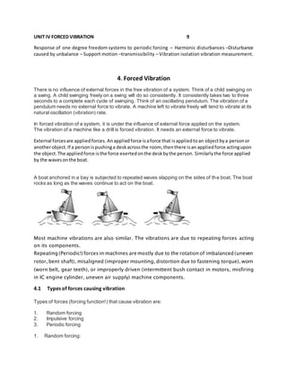
  • 1. UNIT IV FORCED VIBRATION 9 Response of one degree freedom systems to periodic forcing โ€“ Harmonic disturbances โ€“Disturbance caused by unbalance โ€“ Support motion โ€“transmissibility โ€“ Vibration isolation vibration measurement. 4. Forced Vibration There is no influence of external forces in the free vibration of a system. Think of a child swinging on a swing. A child swinging freely on a swing will do so consistently. It consistently takes two to three seconds to a complete each cycle of swinging. Think of an oscillating pendulum. The vibration of a pendulum needs no external force to vibrate. A machine left to vibrate freely will tend to vibrate at its natural oscillation (vibration) rate. In forced vibration of a system, it is under the influence of external force applied on the system. The vibration of a machine like a drill is forced vibration. It needs an external force to vibrate. External forcesare appliedforces. Anappliedforce isaforce that isappliedtoan objectbya personor anotherobject.If a personispushinga deskacrossthe room, thenthere isan appliedforce actingupon the object.The appliedforce isthe force exertedonthe deskbythe person. Similarlythe force applied by the wavesonthe boat. A boat anchored in a bay is subjected to repeated waves slapping on the sides of the boat. The boat rocks as long as the waves continue to act on the boat. Most machine vibrations are also similar. The vibrations are due to repeating forces acting on its components. Repeating (Periodic!) forces in machines are mostly due to the rotation of imbalanced (uneven rotor, bent shaft), misaligned (improper mounting, distortion due to fastening torque), worn (worn belt, gear teeth), or improperly driven (intermittent bush contact in motors, misfiring in IC engine cylinder, uneven air supply) machine components. 4.1 Types of forces causing vibration Types of forces (forcing function!) that cause vibration are: 1. Random forcing 2. Impulsive forcing 3. Periodic forcing 1. Random forcing:
  • 2. These are unpredictable and non-deterministic (difficult to determine the magnitude using expression) Examples: Ground motion during earth quake, jet engine noise. 2. Impulsive forcing: They are short duration forces and non-periodic. The vibrations die out soon and are not significant. Examples: Rock explosion, gun firing, punching die. 3. Periodic forcing: These are predictable and deterministic (magnitude given by an expression). Example: Centrifugal (unbalanced) forces caused by an eccentric rotating mass, Inertia (unbalanced) forces caused by reciprocating mass in an IC engine. 4.1.1 Types of forced vibrations Classifications based on forces causing vibration I. Forced vibrations are classified according to the type of forces causing the excitation: 1. Random vibration 2. Transient vibration 3. Steady state vibration 1. Random vibration: Vibrations caused by random forces are called random vibration. Examples: Ground motion during earth quake, jet engine noise. 2. Transient vibration: Vibrations caused by impulsive forces and which are of short duration are called transient vibration. Examples: Rock explosion, gun firing, punching die. 3. Steady state vibration: Periodic vibration with constant amplitude is called steady state vibration. Example: Centrifugal (unbalanced) forces caused by an eccentric rotating mass under steady state, Inertia (unbalanced) forces caused by reciprocating mass in an IC engine under steady state. II. Classifications based on damping resistance Forced vibrations are also classified into two types based on the existence of damping resistance: 1. Undamped forced vibration (c = 0) 2. Damped forced vibration (c โ‰  0) where โ€˜cโ€™ is damping coefficient N/(m/s) 1. Undamped forced vibration (c = 0): When the damping resistance is nil in a forced vibration, it is called undamped forced vibration. 2. Damped forced vibration (c โ‰  0): When the damping resistance is present in a forced vibration, it is called damped forced vibration. 4.2 Periodic forcing
  • 3. A force which acts continuously at specific intervals of time is called periodic force. There are two types of periodic forcing: 1. Harmonic forcing and 2. Non-harmonic forcing. 1. Harmonic forcing: When the applied load (force!) varies as a sine or cosine function, it is called harmonic forcing. Example: Sine loading: f(t) = F sin (ฯ‰t) Cosine loading: f(t) = F cos(ฯ‰t) The response of a system to a harmonic excitation (loading!) is called harmonic response. 2. Non-harmonic forcing: . Any harmonicfunction such as sin or cosine is periodic.But the converse is nottrue. Non-harmonic forcing is a type of periodic function that is discontinuous. The restoring force is independent of displacement. It can be represented by either a discrete or combination of sin and cos functions. Example: F(t+tp) = F(t) where t is time, tp is time period 4.2.1 Response to periodic forcing Forces acting on any vibrating machine systemcan be represented in mathematical equation ๐‘š๐‘ฅฬˆ + ๐‘˜๐‘ฅ = ๐‘˜ ๐‘ฆ( ๐œ”๐‘ก) ๐‘คโ„Ž๐‘’๐‘Ÿ๐‘’ ๐œ”๐‘ก = ๐‘›๐œ‹, ๐‘› ๐‘–๐‘  ๐‘Ž๐‘› ๐‘–๐‘›๐‘ก๐‘’๐‘”๐‘’๐‘Ÿ. Consider a system as shown in Fig.14.5.1
  • 4. A roller is guided in the groove of a face cam generates motion from the point O. It is a single degree of freedom system The displacement is expressed by the relation ๐‘ฆ( ๐œ”๐‘ก) = ๐œ”0(1 โˆ’ cos ๐œ”๐‘ก) The far end of the spring of stiffness โ€˜kโ€™ connected to the sliding mass โ€˜mโ€™ is assumed as zero. The roller is assumed to be in its extreme left position when the cam begins zero. [Note: By appropriately choosing the initial zero position (A), we can also express the displacement by the relation ๐‘ฆ ๐ด( ๐œ”๐‘ก) = ๐‘ฆ0 sin ๐œ”๐‘ก ] The differential equation of motion is now ๐‘š๐‘ฅฬˆ + ๐‘˜๐‘ฅ = ๐‘˜๐œ”0(1 โˆ’ cos ๐œ”๐‘ก) The solution of this differential equation is ๐‘ฅ = ๐ด cos ๐œ” ๐‘› ๐‘ก + ๐ต sin ๐œ” ๐‘› ๐‘ก + ๐‘ฆ0 [1 โˆ’ cos ๐œ”๐‘ก 1 โˆ’ ( ๐œ” ๐œ” ๐‘› ) 2] Substituting the boundary conditions, ๐‘ฅ(0) = 0, ๐‘ฅฬ‡(0) = 0 ๐ด = ( ๐œ” ๐œ” ๐‘› ) 2 ๐‘ฆ0 [1 โˆ’ ( ๐œ” ๐œ” ๐‘› ) 2 ] ๐‘Ž๐‘›๐‘‘ ๐ต = 0 Substituting the coefficient values, The complete simplified equation of motion is
  • 5. ๐‘ฅ = ( ๐œ” ๐œ” ๐‘› ) 2 ๐‘ฆ0 cos ๐œ” ๐‘› ๐‘ก [1 โˆ’ ( ๐œ” ๐œ” ๐‘› ) 2 ] โˆ’ ๐‘ฆ0 cos ๐œ”๐‘ก [1 โˆ’ ( ๐œ” ๐œ” ๐‘› ) 2 ] + ๐‘ฆ0 The total motion contains a constant plus two vibrations of differing amplitudes and frequencies. The first term on the right hand side ( ๐œ” ๐œ” ๐‘› ) 2 ๐‘ฆ0 cos ๐œ” ๐‘› ๐‘ก [1 โˆ’ ( ๐œ” ๐œ” ๐‘› ) 2 ] is called starting transient. This is not forcing frequency. This is a vibration at natural frequency ฯ‰n. The presence of friction (damping!) would cause this term to die out after a short period of time. ๐น๐‘œ๐‘Ÿ ๐œ” ๐œ” ๐‘› = 0, ๐‘ค๐‘’ ๐‘”๐‘’๐‘ก ๐‘กโ„Ž๐‘’ ๐‘Ÿ๐‘–๐‘”๐‘–๐‘‘ ๐‘๐‘œ๐‘‘๐‘ฆ ๐‘ ๐‘œ๐‘™๐‘ข๐‘ก๐‘–๐‘œ๐‘› ๐‘ฅ = ๐‘ฆ0[1 โˆ’ cos ๐œ”๐‘ก] If the spring is replaced by a rigid member then k and ฯ‰n become very large. So the mass exactly follows the cam motion. 4.2.2 Harmonic disturbances A part of any moving or rotating machinery is often subjected to forces which vary periodically with respect to time. The parts which are metal elements have both mass and elasticity. Therefore there is a vibration exists. Since machines normally operate at constant speeds and constant output, vibratory forces may have a constant amplitude over a period of time. These varying forces also may vary in magnitude with speed and output. It is general practice to analyse the vibration problems assuming periodically varying force of constant amplitude. 4.2.3 Equation of motion Here we shall consider the application of a single sinusoidal force. The solution contains components of motion at two frequency levels. One at forcing frequency and the other at natural frequency of the system. Since damping is always present in actual systems, component at natural frequency level becomes insignificant after a certain time. Therefore the component that contains only forcing frequency remains. This motion is called steady state motion. The equation of motion is ๐‘š๐‘ฅฬˆ + ๐‘๐‘ฅฬ‡ + ๐‘˜๐‘ฅ = ๐น0 cos ๐œ”๐‘ก
  • 6. Complete solution The complete solution of this equation is ๐‘ฅ = ๐‘’โˆ’๐œ‰๐œ” ๐‘› ๐‘ก( ๐ถ1 sin ๐‘ž๐‘ก + ๐ถ2 cos ๐‘ž๐‘ก) + ๐น0 cos( ๐œ”๐‘ก โˆ’ ๐œ™) โˆš( ๐‘˜ โˆ’ ๐‘š๐œ”2)2 + ๐‘2 ๐œ”2 (i) Transient response The first term on the right hand side (RHS) of the complete solution is a transient term. The exponential part will cause it to decay in a short period of time. (ii) Steady state response When the transient part dies out, only the second part remains. Since this is neither the beginning nor the end, it is called steady state solution. The following expressions are introduced to obtain simplified solution. ๐ผ๐‘›๐‘’๐‘Ÿ๐‘ก๐‘–๐‘Ž ๐‘“๐‘œ๐‘Ÿ๐‘๐‘’ = ๐‘š๐œ”2 ๐‘‹ ๐ท๐‘Ž๐‘š๐‘๐‘–๐‘›๐‘” ๐‘“๐‘œ๐‘Ÿ๐‘๐‘’ = ๐‘๐œ”๐‘‹ ๐‘†๐‘๐‘Ÿ๐‘–๐‘›๐‘” ๐‘“๐‘œ๐‘Ÿ๐‘๐‘’ = ๐‘˜๐‘‹ ๐ธ๐‘ฅ๐‘๐‘–๐‘ก๐‘–๐‘›๐‘” ๐‘“๐‘œ๐‘Ÿ๐‘๐‘’ = ๐น0 ๐œ” ๐‘› = โˆš ๐‘˜ ๐‘š ๐œ‰ = ๐‘ ๐‘ ๐‘ ๐‘ ๐‘ = 2๐‘š๐œ” ๐‘› ๐‘‹ ( ๐น0 ๐‘˜โ„ ) = 1 โˆš(1 โˆ’ ๐œ”2 ๐œ” ๐‘› 2) 2 + (2๐œ‰ ๐œ” ๐œ” ๐‘› โ„ ) 2 ( ๐น0 ๐‘˜โ„ ) = Deflection that a spring of stiffness โ€˜kโ€™ would experience if acted upon by a force ๐น0 . The plot of frequency response namely Amplitude ratio vs Frequency ratio is shown in Fig.15.6
  • 7. 4.2.4 Dynamic magnifier Dynamic magnifier (Magnification factor!) is the ratio of maximum displacement of the forced vibration (amplitude!) to the static deflection due to static force. ๐‘‹ = ๐‘š๐‘Ž๐‘ฅ๐‘–๐‘š๐‘ข๐‘š ๐‘‘๐‘–๐‘ ๐‘๐‘™๐‘Ž๐‘๐‘’๐‘š๐‘’๐‘›๐‘ก ๐‘œ๐‘“ ๐‘“๐‘œ๐‘Ÿ๐‘๐‘’๐‘‘ ๐‘ฃ๐‘–๐‘๐‘Ÿ๐‘Ž๐‘ก๐‘–๐‘œ๐‘› ๐น0 ๐‘˜ = ๐‘†๐‘ก๐‘Ž๐‘ก๐‘–๐‘ ๐‘‘๐‘’๐‘“๐‘™๐‘’๐‘๐‘ก๐‘–๐‘œ๐‘› ๐‘‹ ( ๐น0 ๐‘˜โ„ ) = 1 โˆš(1 โˆ’ ๐œ”2 ๐œ” ๐‘› 2) 2 + (2๐œ‰ ๐œ” ๐œ” ๐‘› โ„ ) 2 4.2.5 Frequency response
  • 8. 4.3 Disturbance causedby unbalance Most of the machines like motors, compressors, engines produce vibrations due to rapid rotation of a small unbalanced mass. The differential equation for such systems is ๐‘š๐‘ฅฬˆ + ๐‘˜๐‘ฅ = ๐‘š ๐‘ข ๐‘’ ๐œ”2 cos ๐œ”๐‘ก ๐‘š = ๐‘ฃ๐‘–๐‘๐‘Ÿ๐‘Ž๐‘ก๐‘–๐‘›๐‘” ๐‘š๐‘Ž๐‘ ๐‘  ๐‘š ๐‘ข = ๐‘ข๐‘›๐‘๐‘Ž๐‘™๐‘Ž๐‘›๐‘๐‘’๐‘‘ ๐‘š๐‘Ž๐‘ ๐‘  ๐‘’ = ๐‘’๐‘๐‘๐‘’๐‘›๐‘ก๐‘Ÿ๐‘–๐‘๐‘–๐‘ก๐‘ฆ 4.3.1 Rotating unbalance
  • 9. The following expressions are introduced to obtain simplified solution. ๐‘š = ๐‘ฃ๐‘–๐‘๐‘Ÿ๐‘Ž๐‘ก๐‘–๐‘›๐‘” ๐‘š๐‘Ž๐‘ ๐‘  ๐‘š ๐‘ข = ๐‘ข๐‘›๐‘๐‘Ž๐‘™๐‘Ž๐‘›๐‘๐‘’๐‘‘ ๐‘š๐‘Ž๐‘ ๐‘  ๐‘’ = ๐‘’๐‘๐‘๐‘’๐‘›๐‘ก๐‘Ÿ๐‘–๐‘๐‘–๐‘ก๐‘ฆ The simplified solution is ๐‘‹ ( ๐‘š ๐‘ข ๐‘’ ๐‘šโ„ ) = ๐œ”2 ๐œ” ๐‘› 2 โˆš(1โˆ’ ๐œ”2 ๐œ” ๐‘› 2) 2 +(2๐œ‰ ๐œ” ๐œ” ๐‘› โ„ ) 2 The plot of frequency response namely Amplitude ratio vs Frequency ratio is shown in Fig.16.2 Fig17.34P589 From the plot we conclude that at high speeds, where the frequency ratio ( ๐œ” ๐œ” ๐‘› )is greater than unity, amplitude X can be reduced only by reducing the mass and eccentricity of the rotating unbalance.
  • 10. Relative motion: ๐‘ ๐‘ฆ0 = ๐œ”2 ๐œ” ๐‘› 2 โˆš(1 โˆ’ ๐œ”2 ๐œ” ๐‘› 2) 2 + (2๐œ‰ ๐œ” ๐œ” ๐‘› โ„ ) 2 4.3.2 Reciprocating unbalance In a reciprocating engine, there is an unbalanced primary inertia force given by ๐‘š๐œ”2 ๐‘Ÿ cos ๐œƒ This primary unbalanced force always acts along the line of stroke with varying magnitude.
  • 11. This reciprocating unbalance can be considered as the horizontal component of an imaginary rotating mass m kept at crank radius r (crank pin!). Now balancing is done in the same way as we have done for rotating unbalance. Let the balancing be done by balancing mass mB at radius rB. The reciprocating unbalance force = Horizontal component of rotating balancing mass ๐‘š๐œ”2 ๐‘Ÿ cos ๐œƒ = ๐‘š ๐ต ๐œ”2 ๐‘Ÿ๐ต cos ๐œƒ However the balancing mass also has a vertical component of its centrifugal force namely ๐‘š ๐ต ๐œ”2 ๐‘Ÿ๐ต sin ๐œƒ This remains unbalanced. Therefore when we attempt to balance horizontal component, a vertical unbalance is introduced! To minimize the unbalance, a compromise is therefore made. Only a fraction (c ) of the reciprocating mass is balanced. ๐‘๐‘š๐‘Ÿ = ๐‘š ๐ต ๐‘Ÿ๐ต If there exists both reciprocating as well as rotating unbalance in a machine, then ๐‘š ๐ต ๐‘Ÿ๐ต = ( ๐‘š ๐‘ข + ๐‘ ๐‘š) ๐‘Ÿ 4.3.3 Damping factor (ฮพ) Damping factor (damping ratio!) is the ratio of actual damping coefficient, c to critical damping coefficient, cc. ๐œ‰ = ๐‘ ๐‘ ๐‘ ๐ผ๐‘“ ๐œ‰ > 1, ๐‘กโ„Ž๐‘’๐‘› ๐‘กโ„Ž๐‘’ ๐‘ ๐‘ฆ๐‘ ๐‘ก๐‘’๐‘š ๐‘–๐‘  ๐‘œ๐‘ฃ๐‘’๐‘Ÿ ๐‘‘๐‘Ž๐‘š๐‘๐‘’๐‘‘. ๐ผ๐‘“ ๐œ‰ = 1, ๐‘กโ„Ž๐‘’๐‘› ๐‘กโ„Ž๐‘’ ๐‘ ๐‘ฆ๐‘ ๐‘ก๐‘’๐‘š ๐‘–๐‘  ๐‘๐‘Ÿ๐‘–๐‘ก๐‘–๐‘๐‘Ž๐‘™๐‘™๐‘ฆ ๐‘‘๐‘Ž๐‘š๐‘๐‘’๐‘‘ ๐ผ๐‘“ ๐œ‰ > 1, ๐‘กโ„Ž๐‘’๐‘› ๐‘กโ„Ž๐‘’ ๐‘ ๐‘ฆ๐‘ ๐‘ก๐‘’๐‘š ๐‘–๐‘  ๐‘ข๐‘›๐‘‘๐‘’๐‘Ÿ ๐‘‘๐‘Ž๐‘š๐‘๐‘’๐‘‘
  • 12. 4.3.4 Steady state response The simplified solution for steady state response X is ๐‘‹ ( ๐‘š ๐‘ข ๐‘’ ๐‘šโ„ ) = ๐œ”2 ๐œ” ๐‘› 2 โˆš(1โˆ’ ๐œ”2 ๐œ” ๐‘› 2) 2 +(2๐œ‰ ๐œ” ๐œ” ๐‘› โ„ ) 2 4.3.5 Absolute amplitude
  • 13. The simplified solution for absolute amplitude X is ๐‘‹ ( ๐‘š ๐‘ข ๐‘’ ๐‘šโ„ ) = ๐œ”2 ๐œ” ๐‘› 2 โˆš(1โˆ’ ๐œ”2 ๐œ” ๐‘› 2) 2 +(2๐œ‰ ๐œ” ๐œ” ๐‘› โ„ ) 2 4.3.6 Relative amplitude The relative amplitude Z is
  • 14. From the plot we conclude that at high speeds, where the frequency ratio ( ๐œ” ๐œ” ๐‘› )is greater than unity, amplitude X can be reduced only by reducing the mass and eccentricity of the rotating unbalance. Relative motion: ๐‘ ๐‘ฆ0 = ๐œ”2 ๐œ” ๐‘› 2 โˆš(1 โˆ’ ๐œ”2 ๐œ” ๐‘› 2) 2 + (2๐œ‰ ๐œ” ๐œ” ๐‘› โ„ ) 2 4.3.7 Phase angle The direction of ๐น0 cos( ๐œ”๐‘ก) will always be ahead of ๐‘˜๐‘‹ cos( ๐œ”๐‘ก โˆ’ ๐œ™) by angle ๐œ™. The phase angle ๐œ™ is ๐“ = ๐ญ๐š๐งโˆ’๐Ÿ 2๐œ‰ ๐œ” ๐œ” ๐‘› โ„ (1 โˆ’ ๐œ”2 ๐œ” ๐‘› 2) 4.3.8 Resultant force on motor Resultant force on motor is the resultant of the forces exerted by the spring and dashpot 4.3.9 Resonance speed Let N be the speed of the driving shaft of the motor at which resonance occurs. The angular speed at which resonance occurs is given by ๐œ” = ๐œ” ๐‘› = โˆš ๐‘˜ ๐‘š Resonance speed N is obtained from the relation ๐œ” = 2๐œ‹๐‘ 60 4.3.10 Amplitude of resonance Amplitude of resonance X is obtained by substituting ๐œ” = ๐œ” ๐‘› in the relation ๐‘‹ ( ๐‘š ๐‘ข ๐‘’ ๐‘šโ„ ) = ๐œ”2 ๐œ” ๐‘› 2 โˆš(1โˆ’ ๐œ”2 ๐œ” ๐‘› 2) 2 +(2๐œ‰ ๐œ” ๐œ” ๐‘› โ„ ) 2 ๐‘‹ ( ๐‘š ๐‘ข ๐‘’ ๐‘šโ„ ) = 1 โˆš(2๐œ‰ ๐œ” ๐œ” ๐‘› โ„ ) 2 = 1 2๐œ‰ ๐œ” ๐œ” ๐‘› โ„
  • 15. ๐‘‹ ( ๐‘š ๐‘ข ๐‘’ ๐‘šโ„ ) = 1 2๐œ‰ ๐œ” ๐œ” ๐‘› โ„ 4.4 Support motion Support motion is also called base excitation. In many situations, the excitation is created (applied!) by the base or support configuration. Example: sinusoidal profile of a road. 4.4.1 Absolute amplitude Absolute harmonic displacement of support is y = Y sin ฯ‰t Absolute displacement of mass m is x. Absolute differential equation of motion is ๐‘š๐‘ฅฬˆ + ๐‘๐‘ฅฬ‡ + ๐‘˜๐‘ฅ = ๐‘Œโˆš ๐‘˜2 + ๐‘2 ๐œ”2 sin( ๐œ”๐‘ก + ๐›ผ)
  • 16. ๐‘ญ ๐ŸŽ = ๐’€โˆš ๐’Œ ๐Ÿ + ๐’„ ๐Ÿ ๐Ž ๐Ÿ 4.4.2 Relative amplitude Relative amplitude is z = y-x, where x is absolute displacement of mass m. Relative differential equation of motion is ๐‘š๐‘งฬˆ + ๐‘๐‘งฬ‡ + ๐‘˜๐‘ง = ๐‘š๐œ”2 ๐‘Œ(sin ๐œ”๐‘ก) ๐น0 = ๐‘š๐œ”2 ๐‘Œ 4.4.3 Circular frequency of vibration Natural circular frequency of motion ๐œ” ๐‘› = โˆš ๐‘˜ ๐‘š ๐‘‡๐‘–๐‘š๐‘’ ๐‘๐‘’๐‘Ÿ๐‘–๐‘œ๐‘‘ = ๐‘Š๐‘Ž๐‘ฃ๐‘’ ๐‘™๐‘’๐‘›๐‘”๐‘กโ„Ž ๐‘‰๐‘’๐‘™๐‘œ๐‘๐‘–๐‘ก๐‘ฆ โ†’ ๐‘ก ๐‘ = ๐œ† ๐‘ฃ 4.4.4 Vertical amplitude of vibration Steady state amplitude due to excitation of support,
  • 17. ๐‘ฟ = ๐’€โˆš ๐Ÿ+( ๐Ÿ๐ƒ ๐Ž ๐Ž ๐’ ) ๐Ÿ โˆš[ ๐Ÿโˆ’( ๐Ž ๐Ž ๐’ ) ๐Ÿ ] ๐Ÿ +( ๐Ÿ๐ƒ ๐Ž ๐Ž ๐’ ) ๐Ÿ 4.5 Vibrationisolation Vibrations are produced in all machines having motion of unbalanced masses. These vibrations will be transferred to the foundation or base supports upon which the machines are installed. This will result in noise, wear, and failure of machine as well as the structure. Hence this is not desirable and needs to be eliminated (isolated!). If not at least diminish to acceptable limits. 4.5.1 Transmissibility Transmissibility is defined as the ratio of force or displacement transmitted to the foundation to the vibrating force or displacement applied by the unbalance. Transmissibility is a measure of effectiveness of the vibration isolating material. 1. Force transmissibility In order to reduce the transmitting forces to the foundation, machines are mounted on springs and dampers or some other isolation materials like cork, rubber which have these properties. Definition: Force Transmissibility is defined as the ratio of force transmitted to the foundation to the vibrating force applied by the unbalance. Transmissibility is a measure of effectiveness of the vibration isolating material. Force transmissibility is also called as isolation factor. TransmissibilityvsFrequencyratio The transmitted force to the foundation is a vector sum of spring force (kX) and damping force (cฯ‰X). The spring force and damping force act perpendicular to each other. Therefor the resultant transmitted force Ft is ๐น๐‘ก = โˆš( ๐‘˜๐‘‹)2 + ( ๐‘๐œ”๐‘‹)2 = ๐‘‹โˆš๐‘˜2 + ( ๐‘๐œ”)2. ๐‘‹ ( ๐น0 ๐‘˜โ„ ) = 1 โˆš(1 โˆ’ ๐œ”2 ๐œ” ๐‘› 2) 2 + (2๐œ‰ ๐œ” ๐œ” ๐‘› โ„ ) 2 Multiplying the above two equations ๐น๐‘ก ๐‘˜๐‘‹ ๐น0 = ๐‘‹โˆš๐‘˜2 + ( ๐‘๐œ”)2 โˆš(1 โˆ’ ๐œ”2 ๐œ” ๐‘› 2) 2 + (2๐œ‰ ๐œ” ๐œ” ๐‘› โ„ ) 2
  • 18. โ†’ ๐น๐‘ก ๐น0 = 1 ๐‘˜ โˆš๐‘˜2 + ( ๐‘๐œ”)2 โˆš(1 โˆ’ ๐œ”2 ๐œ” ๐‘› 2) 2 + (2๐œ‰ ๐œ” ๐œ” ๐‘› โ„ ) 2 โ†’ ๐น๐‘ก ๐น0 = โˆš1+( ๐‘๐œ” ๐‘˜ ) 2 โˆš(1โˆ’ ๐œ”2 ๐œ” ๐‘› 2) 2 +(2๐œ‰ ๐œ” ๐œ” ๐‘›โ„ ) 2 (1) We know that ๐œ” ๐‘› = โˆš ๐‘˜ ๐‘š ; ๐œ‰ = ๐‘ ๐‘ ๐‘ ; ๐‘ ๐‘ = 2๐‘š๐œ” ๐‘›; โ†’ ๐‘š = ๐‘ ๐‘ 2๐œ” ๐‘› = ( ๐‘ ๐œ‰ ) 2๐œ” ๐‘› = ๐‘ 2๐œ‰ ๐œ” ๐‘› โ†’ ๐œ” ๐‘› = โˆš ๐‘˜(2๐œ‰๐œ” ๐‘›) ๐‘ โ†’ ๐œ” ๐‘› 2 = ๐‘˜(2๐œ‰๐œ” ๐‘›) ๐‘ โ†’ ๐œ” ๐‘› = ๐‘˜2๐œ‰ ๐‘ โ†’ ๐‘ ๐‘˜ = 2๐œ‰ ๐œ” ๐‘› Substituting the value for ( ๐‘ ๐‘˜ ) in equation (1) ๐‘‡๐‘Ÿ๐‘Ž๐‘›๐‘ ๐‘š๐‘–๐‘ ๐‘ ๐‘–๐‘๐‘–๐‘™๐‘–๐‘ก๐‘ฆ, ๐œ€ = ๐น๐‘ก ๐น0 = โˆš1 +(2๐œ‰ ๐œ” ๐œ” ๐‘› ) 2 โˆš(1 โˆ’ ๐œ”2 ๐œ” ๐‘› 2) 2 +(2๐œ‰ ๐œ” ๐œ” ๐‘› โ„ ) 2 At resonance, ๐œ” ๐œ” ๐‘› = 1 Hence ๐‘‡๐‘Ÿ๐‘Ž๐‘›๐‘ ๐‘š๐‘–๐‘ ๐‘ ๐‘–๐‘๐‘–๐‘™๐‘–๐‘ก๐‘ฆ, ๐œ€ = ๐น๐‘ก ๐น0 = โˆš1 + (2๐œ‰)2 2๐œ‰ With no damper, c=0 and ๐œ‰ = ๐‘ ๐‘ ๐‘ = 0 Hence ๐‘‡๐‘Ÿ๐‘Ž๐‘›๐‘ ๐‘š๐‘–๐‘ ๐‘ ๐‘–๐‘๐‘–๐‘™๐‘–๐‘ก๐‘ฆ, ๐œ€ = ๐น๐‘ก ๐น0 = ยฑ 1 โˆš(1 โˆ’ ๐œ”2 ๐œ” ๐‘› 2) 2 Transmissibilityregions
  • 19. A plot of ๐œ€ ๐‘ฃ๐‘  ( ๐œ” ๐œ” ๐‘› ) can be drawn for different values of ฮพ. The observations from the plot are 1. Critical value of ( ๐œ” ๐œ” ๐‘› ) = โˆš2 2. When ( ๐œ” ๐œ” ๐‘› ) > โˆš2, ๐‘กโ„Ž๐‘’๐‘› ๐œ€ < 1 3. When ( ๐œ” ๐œ” ๐‘› ) < โˆš2, ๐‘กโ„Ž๐‘’๐‘› ๐œ€ > 1 4. When ( ๐œ” ๐œ” ๐‘› ) = โˆš2, ๐‘กโ„Ž๐‘’๐‘› ๐œ€ = 1 5. When ( ๐œ” ๐œ” ๐‘› ) = 1, ๐‘กโ„Ž๐‘’๐‘› ๐œ€ = โˆž 6. Up to ( ๐œ” ๐œ” ๐‘› ) = 1, increasing ( ๐œ” ๐œ” ๐‘› ) increases ฮต 7. Beyond ( ๐œ” ๐œ” ๐‘› ) = 1, increasing ( ๐œ” ๐œ” ๐‘› ) decreases ฮต 8. Note that as damping ๐‘ ๐‘œ๐‘Ÿ ๐œ‰ is increased, ( ๐œ” ๐œ” ๐‘› ) decreases. Therefore for various regions, the effect of damping varies as above. Include examples from excel file Q15and Example: A machine supportedsymmetricallyonfourspringshasa mass of 80 kg. The mass of the reciprocatingpartis2.2 kg whichmove througha vertical stroke of 100 mm withsimple harmonic motion.Neglectingdamping,determinethe combinedstiffnessof the springssothatthe force transmittedtothe foundationis1/20th of the impressedforce. The machine crankshaft rotatesat 800 rpm. If underactual workingconditions,the dampingreducesthe amplitudesof successive vibrationsby30%,find: (i) the force transmittedtothe foundationat800 rpm, (ii) the force transmittedtothe foundationatresonance,and (iii) the amplitude of the vibrationsatresonance.
  • 20. Unitโ€“ 4 November/December2006; Unit โ€“ 4 November/December2008; Unitโ€“ 4 May/June 2009; Unitโ€“ 4 November/December2009 Unitโ€“ 4 NOVEMBER/DECEMBER 2010 KJ10.38.22 Given: Mass of machine m = 80 kg; No. of support springs n = 4; Mass of reciprocating parts mR = 2.2 kg; Vertical stroke of SHM L = 0.1 m; Neglect damping; Force transmitted to foundation = (1/20) impressed force; Speed of machine crank shaft = 800 rpm; Damping reduces amplitudes of successive vibrations by 30%; Find: (a) Combined stiffness of spring; (b) Force transmitted to the foundation at 800 rpm; (c ) Force transmitted to the foundation at resonance; and (d) Amplitude of vibration at resonance. Solution: mass,m= 80 kg Stroke length, L = 0.1 m; Hence, eccentricity e=crank radius r = L/2= 0.05 m Assuming no damping, i.e. c = 0 and ฮพ=0 we find ฯ‰n Speed, N = 800 rpm Circular frequency, ๐œ” = 2๐œ‹๐‘“ = 2๐œ‹๐‘ฅ13.3333 = Logarithmic decrement, ๐œ• = 1 ๐‘› ln ( ๐‘ฅ0 ๐‘ฅ ๐‘› ) = ๐œ‰๐œ” ๐‘› ๐‘ก ๐‘‘ = 2๐œ‹๐œ‰ โˆš1 โˆ’ ๐œ‰2 = 1 1 ๐‘™๐‘› ( 1 0.7 ) = Damping Factor, ๐œ‰ = ๐‘ ๐‘ ๐‘๐‘Ÿ = โˆš ๐œ•2 4๐œ‹2 + ๐œ•2 = Impressed force, ๐น0 = ๐‘š0 ๐œ”2 ๐‘’ = 2.2๐‘ฅ83.80952 ๐‘ฅ0.05 = Force transmitted, ๐น๐‘‡ = ษ› ๐‘ฅ ๐น0 = 0.05๐‘ฅ702.404 = ๐‘‡๐‘Ÿ๐‘Ž๐‘›๐‘ ๐‘š๐‘–๐‘ ๐‘ ๐‘–๐‘๐‘–๐‘™๐‘–๐‘ก๐‘ฆ ๐‘Ÿ๐‘Ž๐‘ก๐‘–๐‘œ, ษ› = ๐น๐‘‡ ๐น0 = โˆš1 + [2๐œ‰ ( ๐œ” ๐œ” ๐‘› )] 2 โˆš[1โˆ’ ( ๐œ” ๐œ” ๐‘› ) 2 ] 2 + [2๐œ‰ ( ๐œ” ๐œ” ๐‘› )] 2 = 0.05
  • 21. Hence , Resonant frequency, The four springs in parallel, Example:Findthe stiffnessof eachspringwhenarefrigeratorunithavingamassof 30 kg isto be supportedbythree springs.The force transmittedtothe supportingstructure isonly10% of the impressedforce.The refrigeratorunitoperatesat420 r.p.m.(16) Unit โ€“ 4 November/December 2005 JK10.36.20 Given: Mass of refrigerator unit m = 30 kg; No. of support springs n =3; Force transmitted to support structure = 0.1 impressed force ๐œ” ๐‘› = โˆš ๐‘˜ ๐‘’๐‘ž ๐‘š = โˆš ๐‘˜ ๐‘’๐‘ž 80 = 12.2887 โˆด ๐‘˜ ๐‘’๐‘ž = ๐‘› ๐‘  ๐‘˜; ๐‘˜ = ๐‘˜ ๐‘’๐‘ž ๐‘› ๐‘  = 26758.2 4 = Impressed force, ๐น0 = ๐‘š0 ๐œ”2 ๐‘’ = 2.2๐‘ฅ18.28872 ๐‘ฅ0.05 = ๐‘‡๐‘Ÿ๐‘Ž๐‘›๐‘ ๐‘š๐‘–๐‘ ๐‘ ๐‘–๐‘๐‘–๐‘™๐‘–๐‘ก๐‘ฆ ๐‘Ÿ๐‘Ž๐‘ก๐‘–๐‘œ, ษ› = ๐น๐‘‡ ๐น0 = โˆš1 + [2๐œ‰ ( ๐œ” ๐œ” ๐‘› )] 2 โˆš[1 โˆ’ ( ๐œ” ๐œ” ๐‘› ) 2 ] 2 + [2๐œ‰ ( ๐œ” ๐œ” ๐‘› )] 2 = โˆš1 + 2๐‘ฅ0.05665 โˆš[2๐‘ฅ0.05665]2 + 0 = Force transmitted at resonance , ๐น๐‘‡ = ษ› ๐‘ฅ ๐น0 = 8.88219๐‘ฅ36.7926 = ๐‘€. ๐น.= ๐ด ๐‘‹0 == 1 โˆš[1 โˆ’ ( ๐œ” ๐œ” ๐‘› ) 2 ] 2 + [2๐œ‰ ( ๐œ” ๐œ” ๐‘› )] 2 = 1 โˆš[1 โˆ’ 1]2 + [2๐‘ฅ0.05665(1)]2 = Amplitude at resonance, A = M.F. x ๐‘‹0 = ๐‘€. ๐น. ๐น0 ๐‘˜ ๐‘’๐‘ž = 36.7926 26758.2 = ๐‘†๐‘ข๐‘๐‘ ๐‘ก๐‘–๐‘ก๐‘ข๐‘ก๐‘–๐‘›๐‘” ๐‘ฃ๐‘Ž๐‘™๐‘ข๐‘’๐‘  ๐œ” ๐œ” ๐‘› = 1 ๐‘Ž๐‘›๐‘‘ ๐œ‰ = 0.05665,
  • 22. Speed of the unit = 420 rpm Find: (a) Stiffness k of each spring; (b) Deduce the expression for transmissibility. Solution: mass,m= 30 kg; 420 rpm Hence, f=420/60= 7 Hz 44 rad/s 0.1 No damping; Hence, damping coefficient, c = 0 Ns/m 0 Substituting in the equation, 11 13.2665 rad/s 5280 N/m Since the three springsare inparallel, Therefore stiffness of each spring, 1760 N/m 2. Motion transmissibility Definition: Motion transmissibility is the ratio of motion transmitted to the foundation to the vibrating motion applied by the unbalance. Transmissibility is a measure of effectiveness of the vibration isolating material. Motion transmissibility is also called as Amplitude transmissibility. In the case of forced excitation due to support excitation, Motion Transmissibility is the ratio of absolute amplitude of mass of the body to the amplitude of base excitation. Transmissibility is the same whether it is force transmissibility or motion transmissibility. Speed, N = Circular frequency, ๐œ” = 2๐œ‹๐‘“ = 2๐œ‹๐‘ฅ7 = ๐‘‡๐‘Ÿ๐‘Ž๐‘›๐‘ ๐‘š๐‘–๐‘ ๐‘ ๐‘–๐‘๐‘–๐‘™๐‘–๐‘ก๐‘ฆ, ษ› = ๐น๐‘‡ ๐น0 = Damping Factor, ๐œ‰ = ๐‘ ๐‘ ๐‘๐‘Ÿ = 0 ๐‘ ๐‘๐‘Ÿ = ๐‘‡๐‘Ÿ๐‘Ž๐‘›๐‘ ๐‘š๐‘–๐‘ ๐‘ ๐‘–๐‘๐‘–๐‘™๐‘–๐‘ก๐‘ฆ ๐‘Ÿ๐‘Ž๐‘ก๐‘–๐‘œ, ษ› = โˆš1 + [2๐œ‰ ( ๐œ” ๐œ” ๐‘› )] 2 โˆš[1 โˆ’ ( ๐œ” ๐œ” ๐‘› ) 2 ] 2 + [2๐œ‰ ( ๐œ” ๐œ” ๐‘› )] 2 = โˆš1 + 0 โˆš[1 โˆ’ ( 44 ๐œ” ๐‘› ) 2 ] 2 + 0 = 0.10 ( 44 ๐œ” ๐‘› ) 2 = 1 0.10 + 1 = Natural frequency, ๐œ” ๐‘› = 44 โˆš11 = ๐œ” ๐‘› = โˆš ๐‘˜ ๐‘’๐‘ž ๐‘š =; ๐ป๐‘’๐‘›๐‘๐‘’, ๐‘˜ ๐‘’๐‘ž = ๐‘š ๐œ” ๐‘› 2 = 30๐‘ฅ13.26652 = ๐‘˜ ๐‘’๐‘ž = 3 ๐‘˜ ๐‘˜ = ๐‘˜ ๐‘’๐‘ž 3 = 58080 3 =
  • 23. ๐‘ด๐’๐’•๐’Š๐’๐’ ๐‘ป๐’“๐’‚๐’๐’”๐’Ž๐’Š๐’”๐’”๐’Š๐’ƒ๐’Š๐’๐’Š๐’•๐’š, ๐‘จ ๐’€ = โˆš ๐Ÿ + [๐Ÿ๐ƒ ( ๐Ž ๐Ž ๐’ )] ๐Ÿ โˆš[ ๐Ÿ โˆ’ ( ๐Ž ๐Ž ๐’ ) ๐Ÿ ] ๐Ÿ + [๐Ÿ๐ƒ ( ๐Ž ๐Ž ๐’ )] ๐Ÿ ๐‘ป๐’“๐’‚๐’๐’”๐’Ž๐’Š๐’”๐’”๐’Š๐’ƒ๐’Š๐’๐’Š๐’•๐’š ๐’“๐’‚๐’•๐’Š๐’, ๐œบ = ๐‘ญ ๐‘ป ๐‘ญ ๐ŸŽ = โˆš ๐Ÿ + [๐Ÿ๐ƒ ( ๐Ž ๐Ž ๐’ )] ๐Ÿ โˆš[ ๐Ÿ โˆ’ ( ๐Ž ๐Ž ๐’ ) ๐Ÿ ] ๐Ÿ + [๐Ÿ๐ƒ ( ๐Ž ๐Ž ๐’ )] ๐Ÿ Phase lag Phase lagbetween motionof mass (A) andmotion ofsupport (Y) (or) FT and F0 isgiven by the relation: ๐‘ท๐’‰๐’‚๐’”๐’† ๐’๐’‚๐’ˆ, ๐‹ = ๐“ โˆ’ ๐œถ = ๐ญ๐š๐งโˆ’๐Ÿ { ๐Ÿ๐ƒ( ๐Ž ๐Ž ๐’ ) [ ๐Ÿโˆ’ ( ๐Ž ๐Ž ๐’ ) ๐Ÿ ] } โˆ’ ๐ญ๐š๐งโˆ’๐Ÿ ๐Ÿ๐ƒ ( ๐Ž ๐Ž ๐’ ) 4.6 Measurement of vibration The experimental determination of natural frequencies, mode shapes, and damping ratios is called experimental modal analysis. It is based on vibration measurements that fall within general designation of model testing. The objective of modal testing is to acquire frequency response functions (FRFs) that are accurate and extensive, in both frequency and spatial domains. Prior knowledge of vibration analysis, instrumentation, signal processing, and modal identification are required to understand the modal testing. The basic aim of modal testing is to obtain (FRFโ€™s) relating to output vibration responses at a number of coordinates of interest. They are in the form of accelerations (velocities, displacements) to input vibration excitations, in the form of driving forces, applied at a given coordinate.
  • 24. Excitation mechanism; Sensing mechanism; Data acquisition and processing mechanism. 4.6.1 Instruments for vibration measurement Vibration instruments are used to measure frequency, displacement, velocity and acceleration of vibration. The measured values are displayed for monitoring. The vibration parameters are also analysed for the purpose of appropriate corrective action. Vibration instruments comprise of transducer, transmitters, data acquisition, display indicators, interface to computers and control devices. Basic measurement system A typical measurement set up consists of Signal generator, power amplifier,exciter,force transducer, response transducer, conditioning amplifier and analyser. Excitationmechanism โ€“It providesinputmotioninthe formof drivingforce appliedata coordinate.The excitationsignalscanbe in manyforms (impulse,random, steppedsine etc.) Itcan be controlledbothin frequency and amplitude. Sensingmechanism โ€“These are sensingdevicesknownastransducers.Piezoelectrictransducersare used for measuringforce excitation.Transducersgenerateelectricsignalsproportionaltophysical parameters one want to measure. Contactlessmotiontransducersimprove the accuracyof dynamicresponse.Laservibrometerisa velocity transducer which works on the principle of Doppler frequency shift of a laser beam light scatteredfrom moving surface. Data acquisitionandprocessingmechanism โ€“The basic objective of the data acquisitionandprocessing mechanismistomeasure the signalsdevelopedbysensingmechanismsandtoascertainthe magnitudes and phasesof the excitationforcesandresponses.These are calledanalysers.Theyincorporate functions based on fast Fourier transform algorithm and provide direct measurement of FRFs Understanding the principles behind signal acquisition and processing is very important for anyone involved with doing vibration measurement and analysis. The validity and accuracy of the experimental results may strongly depend on the knowledge and experience of the equipment user. Vibration Transducers: Acceleration sensor: An accelerometer is a device that measures the vibration, or accelerationof motion of a structure. The force caused by vibration or a change in motion (acceleration) causes the mass to "squeeze" the piezoelectricmaterial whichproducesan electrical charge thatis proportional tothe force exertedupon it. Since the charge is proportional to the force, and the mass is a constant, then the charge is also proportional to the acceleration. Piezoelectricaccelerometersrelyonthe piezoelectriceffectof quartz or ceramic crystals to generate an electrical outputthatisproportional toappliedacceleration. The piezoelectriceffectproducesanopposed accumulationof charged particleson the crystal.This charge is proportional toappliedforce or stress.A force applied to a quartz crystal lattice structure alters alignment of positive and negative ions, which
  • 25. resultsinanaccumulationof these chargedionsonopposedsurfaces.These chargedionsaccumulate on an electrode that is ultimately conditioned by transistor microelectronics. PiezoelectricMaterial There are two types of piezoelectric material that are used in PCB accelerometers: quartz and polycrystalline ceramics. Quartz is a natural crystal, while ceramics are man-made. Each material offers certain benefits, and material choice depends on the particular performance features desired of the accelerometer. Quartz is widely known for its ability to perform accurate measurement tasks and contributes heavily in everyday applications for time and frequency measurements. Velocity Sensor: The velocity probe consists of a coil of wire and a magnet so arranged that if the housing is moved,the magnettendstoremainstationarydue toitsinertia.The relative motionbetweenthe magneticfieldand the coil induces a current that is proportional to the velocity of motion. The unit thus produces a signal directly proportional to vibration velocity. It is self-generating and needs no conditioning electronics in order to operate, and it has a relatively low electrical output impedance making it fairly insensitive to noise induction. Applications: Measurements on Structures or Machinery Casings: Accelerometers and Velocity Sensors are
  • 26. usedin gas turbines,axial compressors,small andmid-size pumps. These sensorsdetecthighfrequency vibration signals related to bearing supports, casing and foundation resonances, vibration in turbine/compressor vanes, defective roller or ball bearings, noise in gears, etc. Displacement measurements relative to rotating shafts: Proximity Probes (capacitance or eddy-current) are used in turbo machinery supported on fluid film bearings, centrifugal compressors, gears and transmissions,electricmotors,largepumps(>300HP),some turbinesandfans. Thesesensorsdetectshaft static displacements, unbalance response, misalignment, shaft bending, excessive loads in bearings, dynamic instabilities, etc. Accelerometers Advantages Simple toinstall Good response athighfrequencies StandhighTemperature Small size Disadvantages Sensitivetohighfrequencynoise Require external power Require electronicintegrationforvelocityanddisplacement. Velocity Sensors Advantages Simple toinstall Good response inmiddlerange frequencies Standhightemperature Do not require external power Lowestcost Disadvantages Low resonantfrequency&phase shift Crossnoise Big andheavy Require electronicintegrationfordisplacement Proximity Sensors Advantages Measure static anddynamicdisplacements Exact response atlowfrequencies No wear Small andlowcost Disadvantages Electrical andmechanical noise Boundedbyhighfrequencies
  • 27. Notcalibratedforunknownmetal materials Require external power Difficulttoinstall Types of Velocity Sensors: Electromagneticlinearvelocitytransducers:Typicallyusedtomeasure oscillatoryvelocity.A permanent magnet moving back and forth within a coil winding induces an emf in the winding. This emf is proportional tothe velocityof oscillationof the magnet.Thispermanentmagnetmay be attachedtothe vibrating object to measure its velocity. Electromagnetictachometergenerators:Usedto measure the angularvelocityof vibrating objects.They provide an output voltage/frequency that is proportional to the angular velocity. DC tachometersuse a permanent magnet or magneto, while the AC tachometers operate as a variable coupling transformer, with the coupling coefficient proportional to the rotary speed. Types of Acceleration Sensors Capacitive accelerometers : Used generally in those that have diaphragm supported seismic mass as a moving electrode and one/two fixed electrodes. The signal generated due to change in capacitance is post-processed using LC circuits, to output a measurable entity. Piezoelectric accelerometers : Acceleration acting on a seismic mass exerts a force on the piezoelectric crystals, which then produce a proportional electric charge. The piezoelectric crystals are usually preloadedsothat eitheranincrease or decrease inaccelerationcausesachange in the charge produced by them. But they are not reliable at very low frequencies. Potentiometric accelerometers : Relatively cheap and used where slowly varying acceleration is to be measured with a fair amount of accuracy. In these, the displacement of a spring mass system is mechanicallylinkedtoaviperarm,whichmovesalongapotentiometricresistive element.Variousdesigns may have either viscous, magnetic or gas damping. Reluctive accelerometers : They compose accelerometers of the differential transformer type or the inductance bridge type.The AC outputsof these vary in phase as well as amplitude.Theyare converted into DC by means of a phase-sensitive demodulator. Servoaccelerometers:These use the closedloopservosystemsof force-balance,torque-balance ornull- balance to provide close accuracy. Acceleration causes a seismic mass to move. The motion is detected by one of the motion-detectiondevices,whichgenerate asignal that acts as an error signal inthe servo- loop.The demodulatedandamplifiedsignalisthenpassedthroughapassive dampingnetworkandthen appliedtothe torquingcoil locatedat the axisof rotationof the mass. The torque is proportional tothe coil current, which is in turn proportional to the acceleration. StrainGage accelerators:these canbe made verysmall insize andmass.The displacementof the spring- mass systemisconvertedintoachange in resistance,due to strain,infourarms of a Wheatstone bridge. The signal is then post-processed to read the acceleration.
  • 28. FLG are NOT REQUIRED 4.1 Applied force (FI): 4.2 Inertia force (FI): Inertiaforce isa propertyof matterby virtue of whicha bodyresistsany change inlinearvelocity(v).FI = โ€“ m R a G where mR ismass of the reciprocatingbodyinkgand a G islinearaccelerationof the center of mass of the body in m/s 2 The negative sign indicates that the inertia force acts in opposite direction to that of the acceleration. Inertia force acts through the centre of mass of the body. 4.3 Inertia Torque (I): Inertiatorque isa propertyof matterby virtue of whicha body resistsanychange in the angularvelocity ( ฯ‰). Inertia torque, TI = โ€“ IG ฮฑ where I G is mass moment of inertia of the body about an axis passing through the centre of mass in kg m 2 , ฮฑ is angular acceleration of the body in rad / s 2 The negative sign indicates that the inertia torque acts in opposite direction to that of the angular acceleration.