2. Agenda
• Introduction and history of subsea engineering
• A simple example of a subsea field
• Challenges unique to subsea systems
• Regulations, codes and standards
3. Agenda
• Introduction and history of subsea engineering
• A simple example of a subsea field
• Challenges unique to subsea systems
• Regulations, codes and standards
4. Introduction
• Subsea systems are oil and gas
production systems (wells) located
underwater beneath the sea
surface
• Shallow to deep waters
• Many offshore oil and gas fields use
subsea systems
• A wide range of equipment and
technologies are required to
explore, drill and develop subsea oil
and gas
Source: Offshore Technology
Source: Ya Libnan
Source: Subsea World News
Surface wells – pumpjacks
Offshore oil and gas field
Subsea system
5. History of Subsea Engineering
• 1897: First offshore well completed within
sight of land, Summerland Offshore Fields
• 1947: First offshore well completed away
from land, Kerr-McGee Kermac No. 16,
GoM, depth = 4.6 m
• 1961:First subsea well completion, West
Cameron 192, GoM, depth = 17 m
• 1983: First subsea well completion on NCS,
Total North East Frigg, depth = 100 m
• At present: > 5000 subsea wells completed
on world-wide basis, > 800 on NCS, record
depth = 2 900 m
Many of the earliest offshore oil wells were drilled
from piers at Summerland in Santa Barbara County,
California.
This Kerr-McGee drilling platform, known as Kermac
Rig No. 16, was the first offshore rig in the Gulf of
Mexico that was out of sight of land.
Source: Wikipedia
Source: Pinterest
6. Current Status of Subsea Wells
• Most subsea wells completed in the last 20 years
• > 5000 subsea wells to-date vs 37 500 surface wells in 2016 alone
Source: Quest Subsea Database. www.questoffshore.com
Source: Quest Subsea Database. www.questoffshore.com
7. Agenda
• Introduction and history of subsea engineering
• A simple example of a subsea field
• Challenges unique to subsea systems
• Regulations, codes and standards
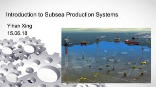
8. How does a Subsea Field look like?
Source: Oil and Gas People
Platforms at sea
surface
Subsea
equipment on
seabed
Subsea
umbilicals, risers,
flowlines (SURF)
9. A Simple Subsea Field
• Subsea Wellhead
• Subsea Christmas
Tree
• Subsea Manifold
• Subsea Pipeline
• Subsea Riser
• Process Platform
Christmas tree
Source: Sandeep S Rangapure
10. A Simple Schematic
Oil reservoir
Subsea
wellhead
Process facility
Seabed
Sea level
Subsea
pipeline
Riser Riser
Subsea
pipeline
Onshore
facility
Subsea
Christmas tree
Nyhamna Gas Processing Facility Source: Hydrocarbons Technology
Source: Statoil
Ekofisk Field Complex
Source: Offshore Energy Today
Source: Offshore Technology
Source: Bardot Group
11. A More Complex Schematic
On seabed
Subsea
manifold
Subsea
wellhead
Subsea
pipeline Subsea
Christmas tree
To process
facility
Source: Statoil
Source: Offshore Energy Today
12. • Interface for drilling and
production equipment (Christmas
tree)
• Suspends the casing
– Casing is the permanently
installed pipe used to line the
well hole for pressure
containment and collapse
prevention during the drilling
phase (cementing)
• Supends the production tubing
– Tubing is removable pipe
installed in the well through
which well fluids pass
Subsea Wellhead
Source: Offshore Magazine
Source: Rigzone
Source: Nustar Technologies Pte Ltd
Source: Sandeep S Rangapure
13. • Acts as safety barrier to stop
produced or injected fluid
• Injection of chemicals to well or
flowline for flow assurance
purposes
• Control of downhole valves
• Transmitt electric signals to/from
downhole gauges
• Regulate fluid flow through a
choke
• Allow for well intervention
Subsea Christmas Tree
Source: Offshore Energy Today
Source: Houston Chronicle
Source: Sandeep S Rangapure Source: PennEnergy
14. Subsea Manifold
• Subsea flow router
• Connects between
subsea trees and
flowlines
• Used to optimize the
subsea layout
arrangement and reduce
the quantity of risers
connected to the platform
Source: Subsea Pipeline
Source: Sandeep S Rangapure
15. Subsea Pipelines and Risers
• Collectively known as Subsea Umbilicals, Risers and
Flowlines (SURF)
• Risers and pipelines transport production/injection fluids
• Umblicals (not shown) are bundles of electrical/hydraulic
cables
• Installed using lay vessels
Pipe sections welded and pushed out
from the back of the ship
Design against loads from fish
trawlers
Source: 2B1st Consulting
Source: Food and Agriculture Organisation of the United Nations Source: www.portalmaritimo.com
Pipeline buckle
Source: Pipeliner Indonesia
Riser
Pipeline
S-lay vessel
Ship moves forward
Source: Sandeep S Rangapure
16. • Crude oil requires processing before
shipping onshore
• Well production is separated into
components of oil, gas, and water (and
sometimes condensate); also remove sand
• Reasons for seperation:
– To allow for fiscal metering
• It is common for several fields to share the same export
system; therefore tracking the oil/gas flow accurately is
important for accounting purposes
– Oil and gas transported in seperate export lines
• Due to differences in design, pressure-boosting requirements
• Sometimes, the gas reserves aren’t econmically enough to
justify a gas export pipeline, Flared or injected back
Process Facility
Source: Statoil Source: Statoil
Source: API
Source: Croft Production Systems
Gravity-based structure Jackets and jack-ups
Flaring of gas
Source: Sandeep S Rangapure
17. Agenda
• Introduction and history of subsea engineering
• A simple example of a subsea field
• Challenges unique to subsea systems
• Regulations, codes and standards
18. Challenges Unique to Subsea Systems
• In addition to loading conditions faced by typical oil and
gas equipment, subsea equipment face the following
unique challenges:
– The subsea/ocean environment
– External loads
– Flow assurance considerations
– Remoteness
19. The Subsea/Ocean Environment
• External hydrostatic pressure
– Every 10 m water depth == 1 atm
– Deepest subsea development (Shell Stones)
== 2 900 m == 290 atm!
– Pipeline squeezed like toothpaste
• Constant cold temperture
– ~ 0 ̊C @ 2900 m == massive heat sink ==
potential flow assurance issue
• Seawater corrosion
• Cathodic protection effects on material
properties
Hydrates in a pipeline
CP blocks
Rusted bolt
Source: Offshore Engineering
Source: www.wrenchguru.com
Source: The Naval Arch
21. Flow Assurance Condtions
• Constant cold temperatures == massive heat sink == cold
spots in process fluid == hydrates issues
• Free water + natural gas + high pressure + low
temperature = hydrates
• Chemical injections (methanol)
• Thermal insulation
Subsea insulation
Source: Trelleborg
Hydrates in a pipeline
Source: Offshore Engineering
Source: TechnipFMC
Insulation on a subsea multiphase
meter
22. Remoteness
• Remote monitoring/regular inspections
– Possibility to extend service life using info collected
• Design for life
• Use of ROVs
– Visual inspection of component of interest
– Perform tasks using tools
• Subsea survery
• Use of divers is common on NCS (2 distinct depths, 130 m & 360 m)
Subsea electronics must
operate > 20 - 30 years
Use of ROV is common
Quack Quack
Subsea cable survey and inspection
Subsea diver
Source: IKM
Source: Seamap Source: Bibby HydroMap
Source: Wikipedia
23. Agenda
• Introduction and history of subsea engineering
• A simple example of a subsea field
• Challenges unique to subsea systems
• Regulations, codes and standards
24. Regulations, Standards and Codes
• In addition, there are also the ASME, ASTM, API standards
Materials
Offshore
structures
Drilling
Wellhead
25. The End
• Thank you for your
attention
• Q & A
A Recent Technological Innovation
• World's 1st subsea compression module installed in Åsgard
field, Norway in 2015.
• Boost recovery by 306 million barrels of oil.
• Used to maintain output as reservoir pressure at gas-
producing fields drops over time.
• Putting the compressor on the seabed means a smaller
platform and one less riser, saving capital costs
The good old days!
Source: Statoil
Source: Pinterest