assignmnet material project of bridge.docx
•Download as DOCX, PDF•
0 likes•6 views

material of bridge design

Recommended
More Related Content
Similar to assignmnet material project of bridge.docx
Similar to assignmnet material project of bridge.docx (20)
Recently uploaded
Recently uploaded (20)
assignmnet material project of bridge.docx
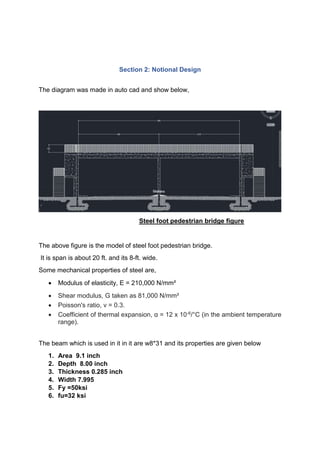
- 1. Section 2: Notional Design The diagram was made in auto cad and show below, Steel foot pedestrian bridge figure The above figure is the model of steel foot pedestrian bridge. It is span is about 20 ft. and its 8-ft. wide. Some mechanical properties of steel are, Modulus of elasticity, E = 210,000 N/mm² Shear modulus, G taken as 81,000 N/mm² Poisson's ratio, ν = 0.3. Coefficient of thermal expansion, α = 12 x 10-6/°C (in the ambient temperature range). The beam which is used in it in it are w8*31 and its properties are given below 1. Area 9.1 inch 2. Depth 8.00 inch 3. Thickness 0.285 inch 4. Width 7.995 5. Fy =50ksi 6. fu=32 ksi
- 2. The components are listed below, Beam / Girder Beam or girder is that part of superstructure structure which is under bending along the span. it is the load bearing member which supports the deck. Span is the distance between points of support (eg piers, abutment). Deck is bridge floor directly carrying traffic loads. Deck transfers loads to the Girders depending on the decking material. Columns or shafts A column or pillar in architecture and structural engineering is a structural element that transmits, through compression, the weight of the structure above to other structural elements below. In other words, a column is a compression member. Stairs “A Stair is a series of steps with or without landings or platforms, which is installed between two or more floors of a building to bridge a large vertical distance”. Stair Case: A part of a building having series of steps is called stair case. Stringer The structural member that supports the treads and risers. It is the part of the stairs that will hold all the weight. This the steel foot pedestrian bridge and we took steel beam w8*31
- 3. Section 3: Load and Analysis The loads are given below, Assume self-weight of a beam =W sw=130 lb/ft Dead load =30+130=160lb/ft=0.16kip/ft Live load= 150lb/ft=0.15kip/ft Wu=1.2(Dead load)+1.6(live load) Wu=1.2(0.16)+1.6(0.15) =0.432 kip/ft Mu = wu L^2 / 8 =(0.432)(20)^2/8 =21.6 kip/ft So we assume Mu=22 kip/ft Step II. Determine unsupported length Lb and Cb Lb = 20 ft and cb=1.14 III. Select a wide-flange shape - Mu/Cb = 22/1.14 = 19.29=20kip-ft. Bf/2 tf <_0.38 sqrt 29000/50 9.2<_2.89 the flange is compact Mn=MP=fyzx =(50)(30.4) =1520kip in =126.666-127 kip ft φbMn=(0.9)(127)=114.3 kip ft φbMn > Mu so w8*31 is selected.
- 4. Shear he factored load and shear are: Wu=1.2(0.16)+1.6(0.15)= 0.432 kip/ft Vu = wu L / 2 = 0.432 (20) / 2 = 4.32 kips w8*31 - Section Properties taken from Part 1 of the AISC Manual d = 8 in tw =0.285 in h / tw =28.070 2.45 sqrt E / Fyw = 2.45 29,000 /36 = 69.54 Since h / tw = 28.070 is < 69.54, the shear strength is governed by shear yielding of the web Vn = 0.60 Fyw Aw = 0.6(36)(7.995)(9.13) = 1576kips φvVn = 0.90(1576) = 1419 > 52.8 kips (OK) The section w8*31 is adequate in resisting the design shear. Buckling Check for local buckling. λ = bf / 2tf = 7.87; Corresponding λp = 0.38 (E/Fy)0.5 = 9.192 Therefore, λ < λp - compact flange λ = h/tw = 50.0; Corresponding λp = 3.76 (E/Fy)0.5 = 90.55 Therefore, λ < λp - compact web Torsion: The formulas for torsion is Now the below diagrams are shown,
- 5. Torsion : Joint reaction : Axial force :
- 7. Moment :