
Recommended
More Related Content
What's hot
What's hot (10)
Viewers also liked
Viewers also liked (18)
Similar to Md pneumatic valve
Similar to Md pneumatic valve (20)
Recently uploaded
Recently uploaded (20)
Md pneumatic valve
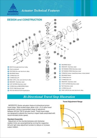
- 1. -28- Bi-Directional Travel Stop Illustration 1 2 3 4 5 6 7 8 9 10 11 12 BODY:Extruded aluminum alloy (Hard anodized) PISTONS:Die cast aluminum alloy BEARING:Nylon O-RING:Buna-N O-RING:Buna-N END CAP(L):Die cast aluminum alloy WASHER: Stainless steel CAP SCREW:Stainless steel O-RING:Buna-NBEARING:Nylon STOP CAM:Sinteral steel PISTON INDICATOR:Polyethylene 13 14 15 16 17 18 19 20 21 22 23 24 25 BEARING:Nylon WASHER: Stainless steel RETAINING RING:Stainless steel RETAINING RING:Stainless steel PRINION:Carbon steel(Electroless nickel plated) BEARING:Nylon O-RING:Buna-N O-RING:Buna-N WASHER: Stainless steel STOP SCREW:Stainless steel NUT:Stainless steel O-RING:Buna-N END CAP(R):Die cast aluminum alloy MODENTIC-Series actuators feature bi-directional pinion travel stops. Side located stops allow a full +-5 of valve travel adjustment, giving a guaranteed range of adjustmint between 80 and 100 of actuator travel. These travel stops are designed to absorb the maximun impact loads associated with recommended stroke speed. Standard Assembly Adjustment of the counterclockwise and clockwise rotation limits are accomplished by turning the respective left and right stop adjustment screws to reduce or increase output rotation. Travel Adjustment Range +5 -5 -5 80 90 100 +5 DESIGN and CONSTRUCTION Actuator Technical Features
- 2. -29- PERFORMANCE Operation Operating Pressure Range: 40 to 120 PSIG. Maximum Allowable Working Pressure: 150PSIG. Maximum Operating Pressure: 120PSIG. Operating Media: Dry or lubricated non-corrosive gas. Operating Temperature Standard: -40F to +200F For clockwise output, apply pressure to P2, which force the pistons to move together. The volume between the pistons is exhausted at P1 *When required Reverse Rotation the pistons can be inverted in the housing resulting in a clockwise rotation when pressure is applied to P1. *When required, Reverse Rotation the pistons can be inverted in the housing resulting in a clockwise rotation when pressure is applied to P1 and a counterclockwise rotation when P1 is vented. Spring-Return(Top View) For clockwise output, the volume between the pistons is exhausted at P1, causing the springs to force the pistons together. The volume outside the pistons is vented at P2. For counterclockwise output, apply pressure to P1, which force the pistons apart and compress the springs. The linear travel of the pistons is converted to a rotation of the drive shaft by the rack to pinion connection. The volume outside each piston is exhausted at P2. Double-Acting(Top View) For counterclockwise output, apply pressure to P1, which force the pistons apart. The linear travel of the pistons is converted to a rotation of the drive shaft by the rack to pinion connection. The volume outside each piston is exhausted at P2. Actuator Technical Features
- 3. -30- DIMENSIONS (UNIT:MM) Model C-125 C-250 C-450 C1000 C-2250 C-3650 C-5000 C-11000 ISO PATTERN F04 F04 or F05 F05 & F07 F05 & F07 F07 & F10 F10 & F12 F10 & F12 F14 OUTPUTTORQUE AT 80PSI AIR 125IN-LB 250IN-LB 450IN-LB 1000IN-LB 2250IN-LB 3650IN-LB 5000IN-LB 11000IN-LB A 120.0 144.3 149.2 183.0 259.6 304.3 364.4 490.0 B -- 194.6 205.6 250.0 355.0 422.0 487.0 642.0 C 64.0 79.0 98.0 121.0 141.0 176.0 196.0 243.7 D 52.2 57.7 67.4 79.2 89.5 99.1 116.5 138.5 E 62.2 81.4 95.0 119.0 140.5 185.2 204.8 238.2 G 24.0 32.5 32.5 46.2 54.0 79.7 79.4 95.3 H 11.0 12.6 13.8 16.6 18.6 27.3 28.3 35.8 J MxP0.8 M5xP0.8 M6xP1.0 M8xP1.25 M10xP1.5 M12xP1.75 M12xP1.75 M16xP2.0 Model C-125 C-250 C-450 C1000 C-2250 C-3650 C-5000 C-11000 ISO PATTERN F04 F04 or F05 F05 & F07 F05 & F07 F07 & F10 F10 & F12 F10 & F12 F14 OUTPUTTORQUE AT 80PSI AIR 125IN-LB 250IN-LB 450IN-LB 1000IN-LB 2250IN-LB 3650IN-LB 5000IN-LB 11000IN-LB K 23.5 29.7 30.2 33.5 39.0 97.4 99.0 124.7 L 12.5 14.5 18.8 23.0 29.5 35.5 35.5 47.5 M 9.0 11.0 14.0 17.0 22.0 27.0 27.0 36.0 N 10.0 17.0 21.0 25.5 31.0 35.5 35.5 45.0 P M5xP0.8 M5xP0.8/M6xP1.0 M6xP1.0/M8xP1.25 M6xP1.0/M8xP1.25 M8xP1.25/M10xP1.5 M10xP1.5/M12xP1.75 M10xP1.5/M12xP1.75 M16xP2.0 Q 8.0 8.0/10.0 10.0/12.0 10.0/12.0 12.0/15.0 15.0/19.0 15.0/19.0 140.0 W 11.0 12.6 13.8 16.6 18.6 27.3 28.3 35.8 Actuator Technical Features
- 4. -31- Pneumatic Rack & Pinion Actuators TORQUE RATINGS (IN-LBS) Double-Acting Actuators Air Torque Output at Operating Pressure-Psig Spring-Return Actuators Basic C-250 C-450 C-1000 C-2250 C-3650 C-5000 C-11000 Spring Set 2 3 4 5 6 2 3 4 5 6 2 3 4 5 6 2 3 4 5 6 2 3 4 5 6 2 3 4 5 6 2 3 4 5 6 Start 69 104 140 175 209 126 190 254 317 381 279 418 559 698 839 659 990 1320 1650 1980 1053 1573 2091 2625 3144 1560 2340 3130 3910 4690 3400 5100 6790 8490 10200 End 45 67 90 112 135 81 121 162 202 243 179 270 360 450 540 394 590 787 984 1181 607 912 1217 1519 1824 785 1180 1570 1960 2360 1720 2570 3430 4290 5150 Start 76 135 300 690 1152 1590 3460 End 47 83 184 395 659 803 1760 Model Number Spring Torque Output 40 Start 138 113 88 248 203 158 549 449 350 1253 1034 816 2063 1726 1388 2780 2380 1980 6060 5200 4330 End 109 70 31 196 125 54 433 278 120 958 591 226 1570 996 423 1990 1200 414 4360 2650 932 60 Start 201 176 151 126 361 316 271 226 798 698 599 500 1816 1596 1379 1161 2975 2637 2300 1967 3970 3570 3180 2780 8660 7790 6930 6060 End 172 133 93 54 309 238 167 96 682 526 371 212 1521 1154 788 424 2482 1907 1335 744 3180 2400 1600 815 6960 5240 3530 1810 80 Start 263 229 213 189 164 473 428 383 339 293 1048 947 848 749 650 2379 2159 2029 1724 1506 3886 3549 3211 2878 2540 5160 4760 4370 3970 3570 11300 10400 9520 8660 7790 End 234 195 156 116 77 421 350 279 209 137 931 775 618 464 304 2084 1717 1351 984 621 3393 2819 2246 1655 1082 4380 3590 2800 2010 1220 9560 7840 6130 4410 2700 100 Start 326 301 276 251 227 586 541 496 451 406 1297 1196 1097 998 899 2939 2722 2505 2287 2069 4797 4460 4123 3789 3452 6350 5960 5560 5160 4760 13900 13000 12100 11300 10400 End 312 258 218 179 139 533 463 392 321 251 1181 1025 867 710 557 2647 2280 1914 1549 1181 4305 3730 3157 2566 1994 5570 4780 3990 3200 2410 12200 10400 8730 7010 5300 120 Model C-125 C-250 C-450 C1000 C-2250 C-3650 C-5000 C-11000 Air Torque Output at Operating Pressure-Psig 40 63 125 225 500 1125 1825 2500 5500 60 94 187 337 750 1687 2738 3750 8250 80 125 250 450 1000 2250 3650 5000 11000 100 156 312 562 1250 2812 4563 6250 13750 120 188 375 675 1500 3375 5475 7500 16500 Actuator Technical Features