3M Cold Shrink QS-III Inline Splice Kits 35kV - 5467A, 5467A-WG, 5468A, 5468A-WG
•
1 like•733 views

3M Cold Shrink QS-III Inline Splice Kits 35kV - 5467A, 5467A-WG, 5468A, 5468A-WG

Recommended
Recommended
More Related Content
What's hot
What's hot (18)
Viewers also liked
Viewers also liked (15)
Similar to 3M Cold Shrink QS-III Inline Splice Kits 35kV - 5467A, 5467A-WG, 5468A, 5468A-WG
Similar to 3M Cold Shrink QS-III Inline Splice Kits 35kV - 5467A, 5467A-WG, 5468A, 5468A-WG (20)
More from Thorne & Derrick International
More from Thorne & Derrick International (20)
Recently uploaded
Recently uploaded (20)
3M Cold Shrink QS-III Inline Splice Kits 35kV - 5467A, 5467A-WG, 5468A, 5468A-WG
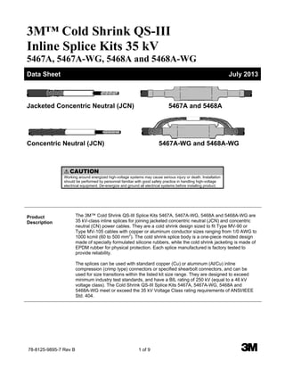
- 1. 78-8125-9895-7 Rev B 1 of 9 3 3M™ Cold Shrink QS-III Inline Splice Kits 35 kV 5467A, 5467A-WG, 5468A and 5468A-WG Jacketed Concentric Neutral (JCN) 5467A and 5468A Concentric Neutral (JCN) 5467A-WG and 5468A-WG Data Sheet July 2013 ! CAUTION Working around energized high-voltage systems may cause serious injury or death. Installation should be performed by personnel familiar with good safety practice in handling high-voltage electrical equipment. De-energize and ground all electrical systems before installing product. Product Description The 3M™ Cold Shrink QS-III Splice Kits 5467A, 5467A-WG, 5468A and 5468A-WG are 35 kV-class inline splices for joining jacketed concentric neutral (JCN) and concentric neutral (CN) power cables. They are a cold shrink design sized to fit Type MV-90 or Type MV-105 cables with copper or aluminum conductor sizes ranging from 1/0 AWG to 1000 kcmil (60 to 500 mm2 ). The cold shrink splice body is a one-piece molded design made of specially formulated silicone rubbers, while the cold shrink jacketing is made of EPDM rubber for physical protection. Each splice manufactured is factory tested to provide reliability. The splices can be used with standard copper (Cu) or aluminum (Al/Cu) inline compression (crimp type) connectors or specified shearbolt connectors, and can be used for size transitions within the listed kit size range. They are designed to exceed minimum industry test standards, and have a BIL rating of 250 kV (equal to a 46 kV voltage class). The Cold Shrink QS-III Splice Kits 5467A, 5467A-WG, 5468A and 5468A-WG meet or exceed the 35 kV Voltage Class rating requirements of ANSI/IEEE Std. 404. WWW.CABLEJOINTS.CO.UK THORNE & DERRICK UK TEL 0044 191 490 1547 FAX 0044 477 5371 TEL 0044 117 977 4647 FAX 0044 977 5582 WWW.THORNEANDDERRICK.CO.UK
- 2. 3M™ Cold Shrink QS-III Inline Splice Kits 35 kV 5467A, 5467A-WG, 5468A and 5468A-WG 2 of 9 78-8125-9895-7 Rev B Kit Contents for 5467A and 5468A 1 3M™ Cold Shrink Silicone Rubber Splice Body 1 3M™ Cold Shrink Adapter Tube (2 adapters in the 5467A Kit) 1 3M™ Cold Shrink Jacketing Tube 2 3M™ Red Compound Tubes P55/R 6 Scotch® Mastic Sealing Strips 2230 2 Scotch® Rubber Mastic Tape 2228 Rolls 1 Neutral Pad 1 3M™Cable Cleaning Pad CC-3 1 Cable Preparation Template (2 templates in the 5468A kit) 1 Instruction Booklet Kit Contents for 5467A-WG and 5468A-WG 1 3M™ Cold Shrink Silicone Rubber Splice Body 1 3M™ Cold Shrink Adapter Tube (2 adapters in the 5467A-WG kit) 1 3M™ Cold Shrink Jacketing Tube 2 3M™ Red Compound Tubes P55/R 2 Scotch® Mastic Sealing Strips 2230 1 Cable Preparation Template (2 templates in the 5468A-WG kit) 1 Instruction Booklet Splice Features Cold Shrink Design — for quick and easy installation; excellent for cable size transitions Complete Kit — includes the required products to make one splice Silicone Rubber Construction — for good high and low temperature performance Production Tested — partial discharge and A.C. withstand tests to provide reliability Computer Aided Design — for compact size and optimal distribution of electrical field Special Electrode Design — minimizes electrical stress at critical cable/splice interface Applications For splicing 35 kV shielded power cables: For inline splicing For feeder and distribution circuits For jacketed concentric neutral cables (JCN) For concentric neutral cables (CN) For copper or aluminum conductors For use with standard inline crimp connectors For use with specified 3M™ Shearbolt Connectors QCI Series For size transition splicing For direct burial installations For submerged locations Physical and Electrical Properties The 3M™ Cold Shrink QS-III Splice Kits 5467A, 5467A-WG, 5468A and 5468A-WG can be used on cables with a rated operating temperature up to 105°C, and an emergency overload rating of 140˚C. A splice constructed from this kit is rated for 35 kV and meets or exceeds the requirements of IEEE Std. 404. The current rating of the splice meets or exceeds the current rating for the cables on which it is installed. BIL rating is 250 kV, which exceeds the normal 200 kV BIL rating for a 35 kV voltage class.
- 3. 3M™ Cold Shrink QS-III Inline Splice Kits 35 kV 5467A, 5467A-WG, 5468A and 5468A-WG 3 of 9 78-8125-9895-7 Rev B Splice Selection Table Kit Number Cable Insulation O.D. Range Inches (mm) Conductor Size Range AWG or kcmil (mm 2 ) 5467A, 5467A-WG 1.07 - 1.70 (27,2 - 43,2) 1/0 - 350 (60 - 185) 5468A, 5468A-WG 1.24 - 2.07 (31,5 – 52,6) 350 - 1000 (185 - 500) Table 1 Typical Dimensions (Installed Splice) On CN Cable On JCN Cable With Neutral Pad Kit Number Typical Length (L) Inches (mm) Typical Diameter (D1) Inches (mm) Typical Diameter (D2) Inches (mm) 5467A, 5467A-WG 33 (838) 3.60 (91) 3.85 (98) 5468A, 5468A-WG 35 (889) 3.90 (99) 4.15 (105) Table 3 Connector Dimensional Requirements Table Kit Number Minimum O.D. Inches (mm) Maximum O.D. Inches (mm) Maximum Length Inches (mm) Connector O.D. Range Requiring adapters Inches (mm) Aluminum (AI/Cu) Compression Copper (Cu) Compression 3M™ Shearbolt Connector QCI Series 5467A, 5467A-WG 0.51 (13,0) 1.70 (43,2) 6.00 (152) 6.50 (165) 5.12 (130) 0.51 - 1.07 (13,0 – 27,2) 5468A, 5468A-WG 0.87 (22,1) 2.07 (52,6) 7.50 (191) 8.25 (210) 7.83 (199) 0.87 - 1.24 (22,1 – 31,5) Table 2 D1 L D1 D2
- 4. 3M™ Cold Shrink QS-III Inline Splice Kits 35 kV 5467A, 5467A-WG, 5468A and 5468A-WG 4 of 9 78-8125-9895-7 Rev B Typical Physical and Electrical Properties Silicone Rubber (Splice Body – Insulation) Physical Properties Test Method Typical Value* Hardness – Shore A (ASTM D 2240) 50 Elongation (%) (ASTM D 412) 610 Tensile Strength (psi) (ASTM D 412) 1090 (7,5 N/mm 2 ) Modulus @ 100% (psi) (ASTM D 412) 340 (2,3 N/mm 2 ) Permanent Set % (100%, 100°C, 22 hrs) (3M TM 86) 5 Thermal Conductivity (W/m K) (ASTM D 518) 0.24 Electrical Properties Dielectric Strength (V/mil) (ASTM D 149) 370 (14,6 kV/mm) Dielectric Strength, Wet (V/mil) (ASTM D 149) 340 (13,4 kV/mm) Dielectric Constant (ASTM D 150) 3.3 Dielectric Loss (ASTM D 150) 0.005 Volume Resistivity (Ohm-cm) (3M TM 80) 6x10 14 Silicone Rubber (Splice Body – Inner Electrode) Physical Properties Test Method Typical Value* Hardness – Shore A (ASTM D 2240) 43 Elongation (%) (ASTM D 412) 510 Tensile Strength (psi) (ASTM D 412) 880 (6,1 N/mm 2 ) Modulus @ 100% (psi) (ASTM D 412) 200 (1,4 N/mm 2 ) Permanent Set % (100%, 100°C, 22 hrs) (3M TM 86) 4 Electrical Properties Volume Resistivity (Ohm-cm) (3M TM 80) 50 Silicone Rubber (Splice Body – Semi-Con Shell) Physical Properties Test Method Typical Value* Hardness – Shore A (ASTM D 2240) 43 Elongation (%) (ASTM D 412) 520 Tensile Strength (psi) (ASTM D 412) 890 (6,1 N/mm 2 ) Modulus @ 100% (psi) (ASTM D 412) 230 (1,6 N/mm 2 ) Permanent Set % (100%, 100°C, 22 hrs) (3M TM 86) 5 Electrical Properties Volume Resistivity (Ohm-cm) (3M TM 80) 150 *All values are averages, based on several determinations and are not intended for specification purpose.
- 5. 3M™ Cold Shrink QS-III Inline Splice Kits 35 kV 5467A, 5467A-WG, 5468A and 5468A-WG 5 of 9 78-8125-9895-7 Rev B Ethylene Propylene Rubber (Jacketing Tubes) Physical Properties Test Method Typical Value* Color Black Hardness – Shore A (ASTM D 2240) 48 Elongation (%) (ASTM D 412) 635 Tensile Strength (psi) (ASTM D 412) 1680 (11,6 MPa) Modulus @ 100% (psi) (ASTM D 412) 170 (1,17 MPa) Fungus Resistance, 28 days (ASTM G 21) No Growth Permanent Set % (250%, Strain) (5 min. recovery, @ 40°F, 4.4°C) 8.8 14.6 Electrical Properties Dielectric Strength, Orig. (V/mil) (ASTM D 149) 490 (19,1 kV/mm) Dielectric Strength, Wet (V/mil) (ASTM D 149) 465 (18,1 kV/mm) Dielectric Constant, Orig. (ASTM D 150) 5.0 Dielectric Constant, Wet (ASTM D 150) 5.6 *All values are averages, based on several determinations and are not intended for specification purpose. Product (Open Specification) The jacketed concentric neutral (JCN) and concentric neutral (CN) power cable splice shall meet the requirements of ANSI/IEEE Std. 404 for a 35 kV rating, and must be rated by the manufacturer for use on 35 kV class cable systems. It must be rated for continuous operation at 105°C, with an emergency overload temperature rating of 140°C. The splice shall be capable of splicing cables with copper or aluminum conductors sized from 1/0 AWG to 350 kcmil (60-185mm 2 ) and 350 to 1000 kcmil (185-500mm 2 ) or accommodate a conductor size transition within those size ranges. The splice shall be of a cold shrink design which does not require any additional heat source for installation. The cold shrink splice body must be of a molded design made of silicone rubber. The splice jacketing shall be of a cold shrink tubing made of EPDM rubber. The color of the splice body and outer jacket shall be black. Engineering/ Architectural (Closed Specification) Splicing of all 35 kV rated cables, jacketed concentric neutral (JCN) and concentric neutral (CN) power cables, sized from 1/0 AWG to 1000 kcmil (60 to 500 mm2 ) copper or aluminum, shall be performed in accordance with the instructions provided with the 3M™ Cold Shrink QS-III Splice Kits 5467A, 5467A-WG, 5468A and 5468A-WG.
- 6. 3M™ Cold Shrink QS-III Inline Splice Kits 35 kV 5467A, 5467A-WG, 5468A and 5468A-WG 6 of 9 78-8125-9895-7 Rev B Performance Test IEEE Std. 404 35 kV Voltage Rating Design Test and Sequence Test Requirement Minimum partial discharge (corona) level 30 kV-rms @ < 3pC Alternating-current 1 minute withstand 71 kV–rms Direct-current 15 minute withstand 125 kV–dc Impulse withstand (BIL) at 25˚C (77˚F)* ±200 kV–crest (150 kV)* Impulse withstand (BIL) at 140˚C (284˚F)* ±200 kV–crest (150 kV)* Minimum partial discharge (corona) level 30 kV–rms @ < 3 pC Cyclic aging (in air and water) 61 kV–rms Minimum partial discharge (corona) level 30 kV–rms @ < 3 pC High voltage time: 5 hr. alternating-current withstand 71 kV–rms 5 min. alternating-current withstand 91 kV–rms Short-time current (ICEA P–32–382 and ANSI/IEEE C37.09) 250°C conductor temp with no damage Alternating-current 1 minute withstand 71 kV–rms Shielding IEEE Std. 592 Connector thermal and mechanical ANSI C119.4 Production Test Test Requirement Production splices tested 100% Minimum partial discharge (corona) level 13 kV–rms @ < 3 pC Alternating-current 1 minute withstand 35 kV–rms *Notes: (1) BIL rating for 5467A, 5467A-WG, 5468A and 5468A-WG QS–III is upgraded to ±250 kV–crest. (2) Impulse test wave is 1.2 x 50 µsec. (ANSI/IEEE Std. 4). Operating Temperature Reference: AEIC CS5 and AEIC CS6: Normal Operation: 105°C Emergency Operation: 140°C Installation Techniques for 5467A and 5468A Kits Detailed instructions for installing the 3M™ Cold Shrink QS-III Splice Kits 5467A and 5468A are included with each kit. A Cable Preparation Template is provided: 1. Prepare cable according to standard procedure. 2. Slide cold shrink jacketing tube and cold shrink splice body onto prepared cables. 3. Install connector. Dimensional requirements table provided. 4. Apply a tape marker on one cable. 5. Apply 3M™ Red Compound P55/R on cable insulation and fill in edge of cable semi–con. DO NOT use silicone grease. 6. Install splice over connector area, aligning end with tape marker, and removing core by pulling and unwinding counterclockwise. 7. Connect neutral wires. 8. Route neutral wires over the neutral pad which is centered on splice body. 9. Connect ground wire if circuit grounding is required at this location. Apply mastic sealing strips to seal ground wire at end of cable jacket. 10. Apply rubber mastic tape around the end of both cable jackets. 11. Install cold shrink jacketing tube over splice. 12. Connect ground wire to ground if splice is to be grounded. 13. If located in direct sunlight, overwrap splice with vinyl tape.
- 7. 3M™ Cold Shrink QS-III Inline Splice Kits 35 kV 5467A, 5467A-WG, 5468A and 5468A-WG 7 of 9 78-8125-9895-7 Rev B Installation Techniques for 5467A-WG and 5468A-WG Kits Detailed instructions for installing the 3M™ Cold Shrink QS-III Splice Kits 5467A-WG and 5468A-WG are included with each kit. A Cable Preparation Template is provided: 1. Prepare cable according to standard procedure. 2. Slide cold shrink jacketing tube and cold shrink splice body onto prepared cables. 3. Install connector. Dimensional requirements table provided. 4. Apply a tape marker on one cable. 5. Apply 3M™ Red Compound P55/R on cable insulation and fill in edge of cable semi–con. DO NOT use silicone grease. 6. Install splice over connector area, aligning end with tape marker, and removing core by pulling and unwinding counterclockwise. 7. Connect neutral wires along with neutral wires on the splice body . 8. Connect ground wire to neutral wires if circuit grounding is required at this location. 9. Connect ground wire to ground if splice is to be grounded. Maintenance Components of the 3M™ Cold Shrink QS-III Splice Kits 5467A, 5467A-WG, 5468A and 5468A- WG are stable under normal storage conditions. Normal stock rotation procedures are recommended. As provided, in the expanded state, the QS-III splice kits have an on-shelf storage life of three years from the date of manufacture. The installed splices can be field tested using standard field cable testing procedures (reference ANSI/IEEE Std. 400, “Guide for Making High– Direct–Voltage Tests on Power Cable Systems in the Field”). Connectors for QS-III Splices The QS-III Cold Shrink Splice kits are designed to be used with 3M™ Scotchlok™ Connectors 10000, 11000, and 20000 Series, 3M™ Connectors CI-Series, or other UL listed inline compression connectors that fit within the dimension limits listed in the 3M™ Connector Dimensional Requirements Table 2. In addition, the following transition connectors may be used: Kit Number Conductor Sizes (AWG or kcmil) 3M™ Compression Connectors 3M™ Shearbolt Connectors QCI Series 5467A 5467A-WG 1/0 to 2/0 2000T 1/0-2/0 CU/AL QCI-1/0-350 1/0 to 3/0 CI-T4 1/0 to 4/0 2/0 to 3/0 2/0 to 4/0 2000T 2/0-4/0 CU/AL 3/0 to 4/0 CI-T7 2/0 to 250 3/0 to 250 4/0 to 250 3/0 to 350 2000T 3/0-350 CU/AL 4/0 to 350 2000T 4/0-350 CU/AL 250 to 350 2000T 250-350 CU/AL 300 to 350 2000T 300-350 CU/AL 5468A 5468A-WG 350 to 500 2000T 350-500 CU/AL QCI-350-750 350 to 600 500 to 600 350 to 750 500 to 750 500 to 1000 QCI-500-1000 750 to 1000
- 8. 3M™ Cold Shrink QS-III Inline Splice Kits 35 kV 5467A, 5467A-WG, 5468A and 5468A-WG 8 of 9 78-8125-9895-7 Rev B Connectors for QS-III Splices The QS-III Cold Shrink Splice kits are designed to be used with 3M™ Scotchlok™ Connectors 10000, 11000, and 20000 Series, 3M™ Connectors CI-Series, or other UL listed inline compression connectors that fit within the dimension limits listed in the 3M™ Connector Dimensional Requirements Table 2. In addition, the following transition connectors may be used: Kit Number Conductor Sizes (AWG or kcmil) Homac Connectors Burndy Connectors Mac Products 5467A 5467A-WG 1/0 to 2/0 1/0 to 3/0 SAC3/0R1/0 YRB27U25 MLCR 3/0-1/0 1/0 to 4/0 SAC4/0R1/0 2/0 to 3/0 YRB27U26 2/0 to 4/0 SAC4/0R2/0 YRB28U26 MLCR 4/0-2/0 3/0 to 4/0 2/0 to 250 SAC250R2/0 3/0 to 250 SAC250R3/0 4/0 to 250 SAC250R4/0 YRB29U28 MLC 250 + AAR 250-4/0 Adapter 3/0 to 350 4/0 to 350 SAC350R4/0 YRB31U28 MLCR 350-4/0 250 to 350 SAC350R250 YRB31U29 MLC 350 + AAR 350-250 Adapter 300 to 350 5468A 5468A-WG 350 to 500 SAC500R350 YRB34U31 MLC 500 + AAR 500-350 Adapter 350 to 600 YRB36U31 500 to 600 YRB36U34 350 to 750 SAC750R350 MLC 750 + AAR 750-350 Adapter 500 to 750 SAC750R500 YRB39U34 MLCR 750-500 500 to 1000 SAC1000R500 MLCR 1000-750 + AAR 750-500 Adapter 750 to 1000 SAC1000R750 MLCR 1000-750
- 9. 3M™ Cold Shrink QS-III Inline Splice Kits 35 kV 5467A, 5467A-WG, 5468A and 5468A-WG 9 of 9 78-8125-9895-7 Rev B 3M, Scotch and Scotchlok are trademarks of 3M Company. 3 Shelf-Life This product has a 3-year shelf life from date of manufacture when stored in a humidity controlled storage (10°C / 50°F to 27°C / 80 °F and <75% relative humidity). Availability 3M™ Cold Shrink QS-III Splice Kits 5467A, 5467A-WG, 5468A and 5468A-WG are available to splice 35 kV jacketed concentric neutral (JCN) and concentric neutral (CN) power cables. The connectors can be either ordered with the kit or provided separately. Standard dimension copper (Cu) or aluminum (Al/Cu) compression (crimp type) connectors are suitable for use with these splice kits, as are 3M™ Shearbolt Connectors QCI Series. These kits are available from your local authorized 3M electrical distributor. Important Notice All statements, technical information, and recommendations related to 3M’s products are based on information believed to be reliable, but the accuracy or completeness is not guaranteed. Before using this product, you must evaluate it and determine if it is suitable for your intended application. You assume all risks and liability associated with such use. Any statements related to the product, which are not contained in 3M’s current publications, or any contrary statements contained on your purchase order, shall have no force or effect unless expressly agreed upon, in writing, by an authorized officer of 3M. Warranty; Limited Remedy; Limited Liability This product will be free from defects in material and manufacture at the time of purchase. 3M MAKES NO OTHER WARRANTIES INCLUDING, BUT NOT LIMITED TO, ANY IMPLIED WARRANTY OF MERCHANTABILITY OR FITNESS FOR A PARTICULAR PURPOSE. If this product is defective within the warranty period stated above, your exclusive remedy shall be, at 3M’s option, to replace or repair the 3M product or refund the purchase price of the 3M product. Except where prohibited by law, 3M will not be liable for any indirect, special, incidental or consequential loss or damage arising from this 3M product, regardless of the legal theory asserted. Electrical Markets Division 6801 River Place Blvd. Austin, TX 78726-9000 800.245.3573 FAX: 800.245.0329 www.3M.com/electrical Please recycle © 3M 2013 All rights reserved WWW.CABLEJOINTS.CO.UK THORNE & DERRICK UK TEL 0044 191 490 1547 FAX 0044 477 5371 TEL 0044 117 977 4647 FAX 0044 977 5582 WWW.THORNEANDDERRICK.CO.UK