Download to read offline

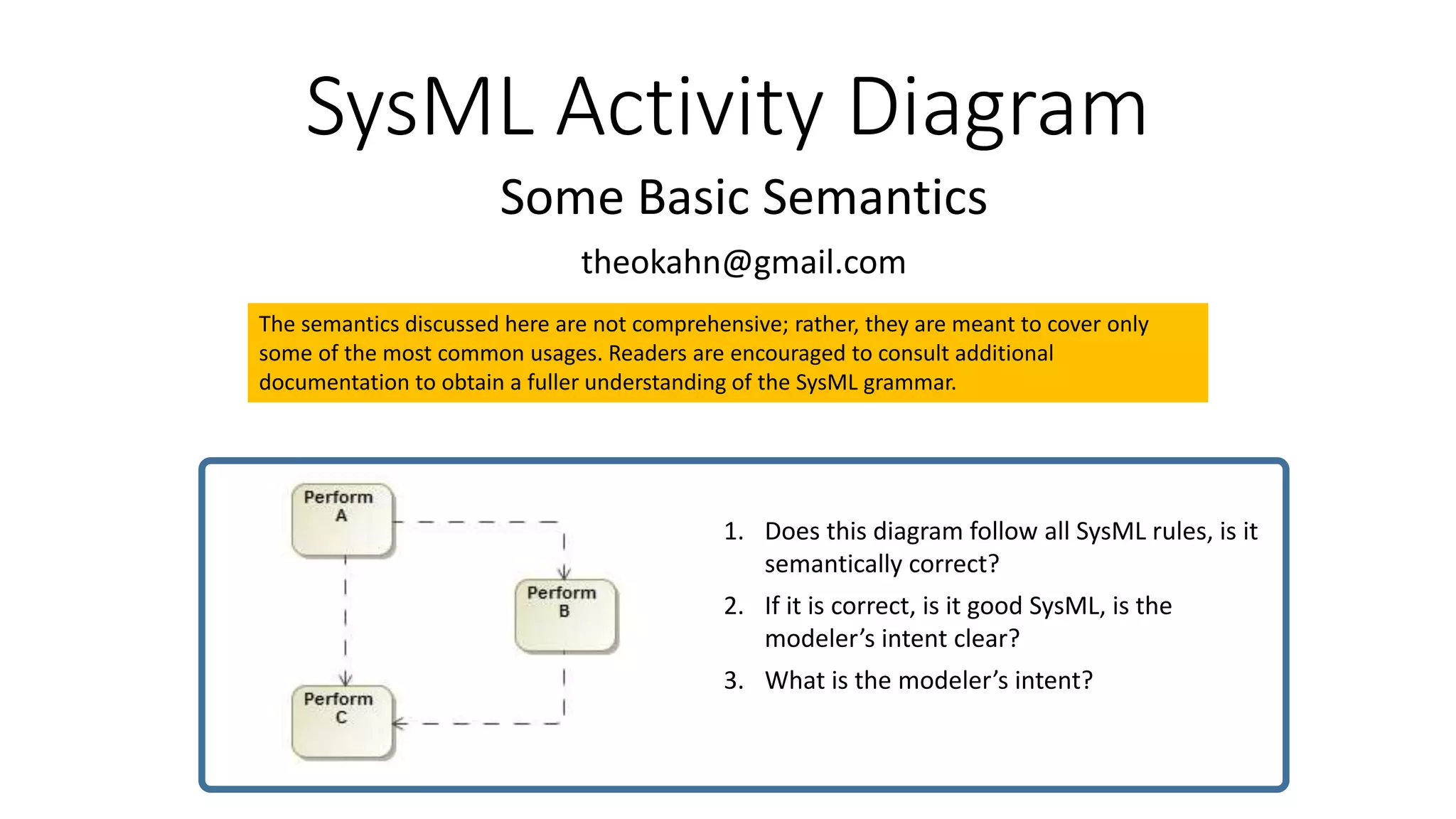
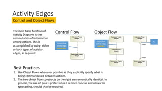
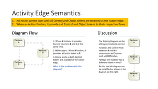
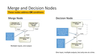
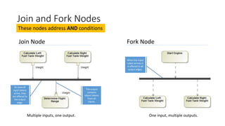
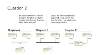
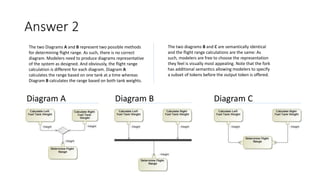

The document discusses some basic semantics of SysML activity diagrams including: - Activity edges can be control flows or object flows to communicate information between actions. Object flows explicitly specify what is being communicated. - Nodes like merge, decision, join, and fork address OR and AND conditions in activity flows. - Two activity diagrams are shown with different ways to determine flight range, with no single correct way but representing the intended system design.


![[LinkedIn]_Thesis Sum in English_New](https://cdn.slidesharecdn.com/ss_thumbnails/55e25e0b-e58f-49d4-98cd-05ee9f54f350-150110123848-conversion-gate01-thumbnail.jpg?width=640&height=640&fit=bounds)


![[Deck] What's New in Spark-Iceberg Integration via DSV2.pptx](https://cdn.slidesharecdn.com/ss_thumbnails/deckwhatsnewinspark-icebergintegrationviadsv2-260210005337-25955b12-thumbnail.jpg?width=640&height=640&fit=bounds)


