
Recommended
Recommended
More Related Content
What's hot
What's hot (19)
Viewers also liked
Viewers also liked (19)
Similar to The International Journal of Engineering and Science (The IJES)
Similar to The International Journal of Engineering and Science (The IJES) (20)
The International Journal of Engineering and Science (The IJES)
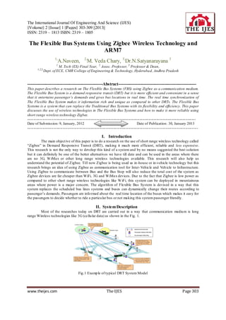
- 1. The International Journal Of Engineering And Science (IJES) ||Volume|| 2 ||Issue|| 1 ||Pages|| 303-309 ||2013|| ISSN: 2319 – 1813 ISBN: 2319 – 1805 The Flexible Bus Systems Using Zigbee Wireless Technology and ARM7 1, 2, A.Naveen, M. Veda Chary, 3,Dr.N.Satyanarayana 3 1 M. Tech (ES) Final Year, 2 Assoc. Professor, 3 Pro fessor & Dean, 1,2,3, Dept. of ECE, CMR College of Engineering & Technology, Hyderaba d, Andhra Pradesh ------------------------------------------------------Abstract-------------------------------------------------------- This paper describes a research on The Flexible Bus Systems (FBS) using Zigbee as a communication medium. The Flexible Bus System is a demand responsive transit (DRT) but it is more efficient and convenient in a sense that it entertains passenger’s demands and gives bus locations in real time. The real time synchronization of The Flexible Bus System makes it information rich and unique as compared to other DRTs. The Flexible Bus Systems is a system that can replace the Traditional Bus Systems with its flexibility and efficiency. This paper discusses the use of wireless technologies in The Flexible Bus Systems and how to make it more reliable using short range wireless technology Zigbee. ------------------------------------------------------------------------------------------------------------------------------------- Date of Sub mission: 9, January, 2012 Date of Publication: 30, January 2013 --------------------------------------------------------------------------------------------------------------------------------------- I. Introduction The main object ive of this paper is to do a research on the use of short range wireless technology called “Zigbee” in Demand Responsive Transit (DRT), making it much more efficient, reliable and less expensive. This research is not the only way to develop this kind of a system and by no means suggested the best solution but it can definitely be one of the better alternatives we have till date and can be used in the areas where there are no 3G, W iMax or other long range wireless technologies available. This research will also help us understand the potential of Zigbee. Till now Zigbee is being used as in -house or in-vehicle technology but this research brings an idea of using Zigbee as communication tool for Inter-Vehicle and Veh icle to Infrastructure. Using Zigbee to communicate between Bus and the Bus Stop will also reduce the total cost of the system as Zigbee devices are far cheaper than WiFi, 3G and WiMax devices. Due to the fact that Zigbee is low power as compared to other short range wireless technologies like W iFi, this system can be deployed in mountainous areas where power is a major concern. The algorith m of Flexible Bus System is devised in a way that this system replaces the scheduled bus lines systems and buses can dynamically change their routes according to passenger’s demands. Passengers are info rmed about the real time location of the buses which makes it easy for the passengers to decide whether to ride a particu lar bus or not making this system passenger friendly. II. System Description Most of the researches today on DRT are carried out in a way that communication mediu m is long range Wireless technologies like 3G (cellu lar data) as shown in the Fig. 1. Fig.1 Examp le of typical DRT System Model www.theijes.com The IJES Page 303
- 2. The Flexible Bus Systems Using Zigbee Wireless Technology And Arm7… Everything in the System is connected to the Control Centreand all the in formation is shared with the Control Centre. Co mmunication between Bus and Control Centre is through 3G; similarly co mmunication between Control Centre and Bus Stop is through 3G. Installing the 3G modules on Bus Stop and Bus which are more than 1 in most of the cases will greatly increase the total installation cost of the system. Following are some drawbacks to this approach. 1. Installation cost is very high. 2. Maintenance cost is very high. 3. High power consumption. 4. Cannot be applied in areas where there are no long range wireless (3G, W iMax) signals availab le (rural or mountainous areas). To overcome these problems we propose a model which is less costly than the system discussed ab ove. We call our proposed system “The Flexib le Bus System”. This paper will only include the wireless communication part of this system. Control Centre is connected to Bus Stops through internet (Wireless or Wired). Fig. 2 shows our proposed system. Fig.2 Proposed Flexible Bus Systems Model As shown in Fig.2 Control Centre and Bus Stops are connected to each other through the internet (wired or wireless). Bus Stop and Bus are connected through short range Wireless Technology “Zigbee”. An interesting feature here is that Bus and Control Centre are not connected to each other directly, they communicate to each other through Bus Stop, means the information transfer fro m Control Centre is first transferred to Bus Stop and then fro m Bus Stop to Bus vice versa. This way there will be no need for 3G module installation in Buses. This will greatly reduce the total cost of the system. The Bus Stops in this system are very smart and we call them “Intelligent Bus Stops”. These Bus Stops are equipped with different devices like RFID card reader; Touch Screen etc. The passengers carry RFID card which contains all the information about the passenger. Whenever a passenger goes to the Bus Stop, he/she will punch his/her RFID card to those RFID card readers installed at Bus Stop and gets recognized by the system. After getting recognized by the system, the passenger can enter the destination and will get the response from the system e.g. on which Bus to ride and how much is the wait t ime, leaving the decision of rid ing the Bus to the passenger. III. Proposed Algorithm The algorithm for this system is devised in such a way that passengers have to wait less on the bus stops and buses drive to the bus stops where passengers are waiting instead of driving to the Bus Stops where there are no passengers. Fig. 3 shows the algorithm flow for The Flexible Bus Systems. Passenger after reaching the Bus Stop punches the RFID Card and all the information (Passenger ID, Destination etc) is transferred to Control Centre which then sends the info on which Bus to ride. Similarly in fo for all the Buses are transferred to Control Centre through Bus Stops and then Route info for the Buses are transferred to Buses through the Bus Stops. Navigation is installed in the bus which guides the Buses about the routes. Fig.3 Algorith m flo w for The Flexib le Bus Systems www.theijes.com The IJES Page 304
- 3. The Flexible Bus Systems Using Zigbee Wireless Technology And Arm7… Fig. 4 shows that a Traditional Bus System has a fixed route, it drives from 1~25 and then back fro m 25~1. The route will remain the same even if there are no passengers on Bus Stop3 and Bus Stop4. However in The Flexib le Bus System the buses can change the routes dynamically depending upon the demand of the passenger. As shown in Fig. 4 every Bus Stop is connected to the Bus Stop next to it. For example Bus Stop1 is c onnected to Bus Stop2 and Bus Stop10. For example if BusA is on Bus Stop2 and a passenger is wait ing on Bus Stop9, then instead of going to the Bus Stop9 by driving to all the Bus Stops from 2~9, the Bus will d irectly drive to Bus Stop9 to pick up the pass enger. This way the wait time of the passenger waiting on Bus Stop9 will be less as compared to the case in which Bus has to drive fro m 2~9. The Flexib le Bus System will not only decrease the wait t ime of the passengers but it will also decrease the drive time of the Buses which will great ly reduce the total cost of the System. Fig.4 Traditional Bus System and the Flexible Bus System Grid Model A smart algorith m is required to efficiently perfo rm the tasks discussed in Fig. 4. We are working on an algorith m that can perform these jobs by keeping the wait t ime o f the passengers on the Bus Stops and Ride t ime of the passengers on the Bus at a low side. Different simulat ion are been carried out for this purpose using our Simu lator called “Konno Simu lator”. Fig.5 shows the comparison of Wait time of passengers on the Bus Stop in Traditional Bus Systems and The Flexib le Bus Systems. Fig.5 Average Wait Time for Passengers on Bus Stop .In Fig. 5 OLD is “Tradit ional Bus Systems” and DEMAND1 is “The Flexib le Bus Systems”. Ratios (25:1, 15:2, 5:3 etc) shown in Fig.5 are No. o f Passenger: No. of Buses. Similarly the ride time of the passengers in the Bus is also very important. Our simu lation results show that using our algorith m ride time of the passengers in th e buses is also less than that of ride time o f the passengers in the bus in Traditional Bus Systems. IV. Zigbee Communication Zigbee Co mmunication between Bus and Bus Stops are the major concern of this paper. The reason Zigbee is given priority over the other short range wireless technologies like WiFi is that in this research only few bytes of data is to be transferred using short range wireless technologies, no heavy data like Audio or Video is transferred so Zigbee seems to be a good alternative to WiFi wh ich offers heavy data transfer. With heavy data comes more power consumption which can be a concern in rural areas where power is not easily available. As described earlier Buses and Bus Stops are going to communicate with each other through Zigbee. Since Control Centre is aware of all the ongoing and carrying all the informat ion about all the buses and bus stops, the informat ion is first transferred to corresponding bus stop about the upcoming bus. Bus Stops and Control Centre are always connected to each other through the internet (Wired or Wireless) so information between Bus Stops and Control Centre can be easily shared. Major concern is the transfer of in formation between the Bus Stops and Buses and that is to be done through Zigbee. This is the core of this research and so the information transfer between the Buses and the Bus Stops are carefully thought of. Fig. 6 shows the sequence of information transfer between Buses and the Bus Stops through Zigbee. www.theijes.com The IJES Page 305
- 4. The Flexible Bus Systems Using Zigbee Wireless Technology And Arm7… Fig. 6 Data Transfer Sequence between Buses and Bus Stops As soon as Bus enters the communication range of the Bus Stop, informat ion exchange starts. The numbers 1~8 in Fig. 6 are described below. 1. Bus sends the Bus ID to Bus Stop. 2. Bus Stop authenticates the request and requests the Bus to Stop or Don’t Stop at current Bus Stop. 3. If Bus is requested to stop at current Bus Stop, Bus sends the stopping signal to Bus Stop. 4. If Bus is requested to pass the Bus Stop without stopping, it sends the Non -Stop passing signal to Bus Stop and requests Next Bus Stop ID. 5. Bus Stop sends the Next Bus Stop ID to the Bus. 6. In case of Bus stopped at current Bus Stop, after the Passengers rode the Bus, Bus Stop requests for the No. of Passengers in the Bus. 7. Bus sends the No. of passengers in the Bus to the Bus Stop and requests for Next Bus Stop ID. 8. Bus Stop sends the Next Bus Stop ID to the Bus. The decision of stopping at Bus Stop is made by Control Centre and is to be made on following conditions • No. of passengers to get off on this Bus Stop • No. of passengers to ride on this Bus • Seats availab le in this Bus • Destination of the passengers Each time information/request is sent by the Bus to the Bus Stop, the informat ion is sent to the Control Centre by the Bus Stop. The Control Centre checks for the validity of the data and sends it back to the Bus Stop from where the data is sent to the Bus. Fig. 7 is a flow chart depiction of Fig. 6 showing an easy to understand flow of informat ion transfer between the Bus and the Bus stop. All th e informat ion received fro m Bus (No. of passengers in the Bus) which is now carried by the Bus Stop will be transferred to the Control Centre through the internet after the Bus leaves the Bus Stop. Fig.7 Data Transfer Flo w Chart between Buses and Bus Stops www.theijes.com The IJES Page 306
- 5. The Flexible Bus Systems Using Zigbee Wireless Technology And Arm7… V. Conducted Experiments Different experiments are performed to check whether Zigbee is suited for this kind of System (Intelligent Bus Systems) or not. Below are the details of experiments. All the experiments are conducted using Max Stream Xbee Pro. Below are the conditions in wh ich experiments are conducted. • Maximu m distance between Xbee Bus and Xbee Bus stop is 100m with maximu m height of 2m. • Maximu m No. of Bytes sent is 7 Bytes. • Experiments are conducted using the Data Transfer Sequence shown in Fig. 6 and Fig. 7. Three types of experiments are conducted to check the eligib ility of Zigbee for The Flexible Bus Systems. 1. Zigbee Co mmunication on straight road with clear Line of Sight. 2. Zigbee Co mmunication on curve with No Line of Sight (Trees as Hurdles) Fig.9 Zigbee Co mmun icate with No Clear Line of Sight (trees as hurdle) 3. Zigbee Co mmunication on curve with No Line of Sight (Bu ild ings as Hurdles) Fig.10 Zigbee Co mmun icate with No Clear Line of Sight (Bu ild ings as hurdle) Table I shows the data collected for Experiment 1 when there is clear line of sight and the road is straight. As shown in Table I, there are no errors when Zigbee Data transfer is checked on the straight road with clear line of sight which shows that Zigbee can be used on straight roads with clear line of sight without any doubts. Table II shows the data collected for Experiment 2 when there is no clear line of sight and there is a curve/turn on road which has some rough trees around. www.theijes.com The IJES Page 307
- 6. The Flexible Bus Systems Using Zigbee Wireless Technology And Arm7… Table II shows the data which is still quite encouraging although there are a few errors, but the average shows that every 6 times data is sent 4.67 t imes it is received. As described earlier if the data is received even only once the communicat ion can be done easily a nd bus can get to know if it has to stop on the upcoming Bus Stop or not but as data is received more than 1 t imes, in this case4.67 times which is far more t imes it should be received, so there shouldn’t be any problem in data commun ication Table III shows the data collected for Experiment 3 when there is no clear line of sight and there is a curve/turn on road which has some buildings around. The data shown in Table III is not very encouraging as error percentageis at high side. Table shows that at distance of 100m erro r rate is 66.67% wh ich means that data is received only 2 times out of 6 which is at a risky side. Similarly at a distance of 80m on average data is received 3.6 times out of 6 which is better than that at 100m but still below par. At a distance of 50m the data is encouraging getting received 4.8 times out of 6. If we concentrate on data for 50m, it seems as if data communication can be done easily as data is received quite frequently but the problem with 50m is that if Bus is sent a sig nal by the Bus Stop to stop at this Bus Stop when Bus is just 50m away fro m the Bus Stop, it will be difficult for the bus to stop with a speed of 60km/h wh ich is the maximu m speed limit here in Japan. A. Experi ments outcome The conducted experiments showed the following results Different experiments showed that the main factor affecting Zigbee commun ication is the distance between the Zigbee modules (Xbee Bus and Xbee Bus Stop in this case). The more the distance the less efficient is the Zigbee co mmunicat ion. The bigger and denser the hurdles, more difficult it is to co mmunicate between the Zigbee Modules. The straighter the roads, the better it is to communicate between Zigbee Modules. A suitable height of about 2m can increase the efficiency of Zigbee Data Transfer. Speed of the car has no significant effect on Zigbee Data Transfer. www.theijes.com The IJES Page 308
- 7. The Flexible Bus Systems Using Zigbee Wireless Technology And Arm7… B. Soluti ons to the problems Below are some proposed solutions to the problems occurred during the experiments. The main problem is less frequency of receiving of Data when there are hurdles like Buildings on road with curves or turns. The proposed solution to this problem is to avoid making the Bus Stops where there are buildings on the roads with curve or turns. Another solution can be to use Relays with Zigbee to increase the range of Zigbee Modules but this will increase the cost of the System. VI. Summary The Flexible Bus Systems is an efficient and a smart Demand Responsive Transit (DRT). It is flexib le in a sense that it can change dynamically according to the demand of the passenger. The system can fu lfil the demands of the passengers in a way that they have to wait less on the Bus Stops and even if they miss the Bus they can be entertained by the next bus without waiting for very long. The use of Zigbee for co mmunication between the Buses and the Bus Stops greatly reduce the total cost of the system. Everything is connected to the Control Centre which is the brain of the system. Control Centre and Bus Stops are connected through the internet and Buses and Control Centre are connected to each other through Bus Stops. All the characters (Buses, Bus Stops and Passengers) are updated with latest informat ion all the times wh ich makes The Flexib le Bus Systems more information rich and reliab le. VII. Acknowledgment This work is supported by the Strategic Information and Co mmunication R&D Pro motion Programme 102302005 fro m the Japanese Ministry of Internal Affairs and Co mmun ications. REFERENCES [1] Shahin Farahani, Zigbee Wireless Networks and Transceivers [2] Lee, E., Ryu, K., Paik, I.: A Concept for Ubiquitous Transportation Systems and Related Develop ment Methodology. In: International IEEE Conference on Intelligent Transportation Systems, pp.37 -42 (2008) [3] Yu wei Li, Jessica Wang, Justin Chen, Michael Cassidy, Design of a Demand -Responsive Transit System (Californ ia PATH Working Paper UCB-ITS-PWP-2007-4) [4] ZHANG Feizhou, CAO Xuejun, YA NG Dongkai, Intelligent Scheduling of Public Traffic Vehicles Based on a Hybrid Genetic Algorithm (TSINGHUA SCIENCE AND TECHNOLOGY, ISSN 1007-0214 09/ 25 pp625-631, Volu me 13, Nu mber 5, October 2008) [5] Jin Xu, Zhe Huang, An Intelligent Model for Urban Demandresponsive Transport System Control (Journal of Software, Vol. 4, No. 7, September 2009) [6] R´emy Chevrier, Philippe Canalda, Pascal Chatonnay and Didier Josselin, Co mparison of three Algorith ms for solving the Convergent Demand Responsive Transportation Problem (Proceedings of the IEEE ITSC 2006) [7] Zigbee Standards Organizat ion, Zigbee Specification, ZigBee Docu ment 053474r17, January 17, 2008.. [8] Tomohiro Utsumi, Sh in Konno, Yusuke Kanno, Ken -ich i Yu kimatsu, Mahito Kobayashi, Masashi Hashimoto, A Feasibility study on the Buffer-Less Routing Networks using Deflection Routing Control (Proceedings of IEICE Vo l. J92-B No. 11 pp. 1741-1749 2009). www.theijes.com The IJES Page 309