
Recommended
Recommended
More Related Content
What's hot
What's hot (20)
Viewers also liked
Viewers also liked (19)
Similar to Development of a power factor model for power sysytem loads
Similar to Development of a power factor model for power sysytem loads (20)
Recently uploaded
Recently uploaded (20)
Development of a power factor model for power sysytem loads
- 1. The International Journal Of Engineering And Science (IJES) || Volume || 3 || Issue || 10 || Pages || 61-66|| 2014 || ISSN (e): 2319 – 1813 ISSN (p): 2319 – 1805 www.theijes.com The IJES Page 61 Development of a power factor model for power sysytem loads Ganiyu A. Ajenikoko1, Anthony A. Olaomi2 1, 2, Department of Electronic & Electrical Engineering, Ladoke Akintola University of Technology, P.M.B. 4000, Ogbomoso, Nigeria. --------------------------------------------------------------ABSTRACT------------------------------------------------------- Power factor is a measure of how efficiently, electrical power is consumed. This paper presents the development of a power factor model for power system loads to establish the effect of power factor correction (PFC) on the electrical distribution network of Lever Brothers Nigeria PLC. Measured data were taken on the distribution network before and after the installation of the PFC capacitors. The data which includes power factors, active power, reactive power, apparent power and current were used as input parameters for the development of a polynomial PF model of order 3.The result of the model reveals a power factor improvement from 0.5671 to 0.9693 after the installation of the PFC capacitors. Analysis of the model can be used to reduce the cost of electric power production and increases the capacity and efficiency of the electrical power systems. Keywords: Power factor, Power factor correction, Active power, Apparent power, Reactive power, Polynomial, Inductive load, Capacitive load, --------------------------------------------------------------------------------------------------------------------------------------- Date of Submission: 11 October 2014 Date of Publication: 05 November 2014 --------------------------------------------------------------------------------------------------------------------------------------- I. INTRODUCTION Power factor (PF) is a measure of how effectively electrical power is being used by a system. A load on an electrical distribution system can be classified as reactive, inductive and capacitive. The inductive load is the most common of these loads in most industries, shops and offices. Examples of these loads are transformers and florescent lights. An inductive load uses energy in order to do its work and also requires a certain amount of energy supply to function properly(Hua et al 2009, Zane and Maksimovic 1999). An inductive load requires two types of power in order to operate active power (measured in KW) which actually perform the work and the reactive power (measured in KVA) which sustains the electromagnetic field and does no actual work(Fu and Chen 2012,Wall and Jackson 2003, Buso et al 2006). The total power consumed in operating the system or the combination of active power and reactive power is called the apparent power(Prodic et al 2003, Fang et al 2009.. The relationship between the active power and apparent power is the power factor(Z hang et al 2005, Zhou and Jovanovic 2011, Zhou et al 2001). Power Factor Correction (PFC) The aftermath of a poor power factor is a substantial increase in cost, hence the need for correction A system with a low power factor requires the supply company to feed more power into the distribution system, so that the customer can operate the electrical equipment and appliances(Osifchin 2011, Lee et al 2011, Peterchev and Sanders 2013). A low power factor on a system can result in the following(Merfert 2007, Xiao et al 2009, Patella et al 2009, Maksimovic and Erickson 2009). - Excessive heat being generated which can damage the life of the equipment - The potentials of fires in extreme situations - Low voltage conditions which result in - sluggish motor operation - dim lights (and the resulting quality and safety problems)
- 2. Development of a power factor model for power sysytem loads www.theijes.com The IJES Page 62 The use of power factor correction equipment has a number of advantages. These are: The equipment can be installed in the form of a capacitor bank as close as possible to the meter power factor. This reduces the total current supplied by the electricity utility to the premises. - It can be used to increase the power carrying capacity cray cables - It forms an economical solution to the problem of filtering out the spikes that causes equipment failure. - Installing filter reactor equipment in series with the capacitor bank increases the continuity and integrity of the supply which result in fewer fluctuation and reduces equipment damage. Benefits of Active Power Factor Correction (PFC). The following benefits are derivable from PFC (Malik 2009, Prodic et al 2012, Maksimovic and Erickson 2009): Reduces Root Mean Square (RMS) input current and ,. facilitates power-supply hold-up. The active PFC circuit maintains a fixed intermediate direct current (DC) bus voltage that is independent of input voltage, so the energy stored in the system does not decrease as the input voltage decreases. This allows the use of smaller and less expensive bulk capacitors - Enables universal input voltage capabilities by providing a constant bus voltage for the entire voltage range. - Improves efficiency of downstream converters. PFC reduces the dynamic voltage range applied to the downstream DC/DC converters. As a result, voltage rating of rectifiers can be reduced, resulting in lower forward drops; and operating duty-cycle/transformers turns ratios can be increased, resulting in lower current in switches and winding. - Increases the efficiency of the power distribution system. Lower RMS current reduces distribution wiring losses. - Reduces the VA rating of standby power generators. - Reduces stresses on neutral conductors. Reducing harmonics eliminates the risk of triplen harmonics ( the third and multiples thereof) that can add to dangerous levels in the neutral conductor of Y-connected 3-phase system. The power factor of the power system is constantly changing due to variations in the size and number of motors being used at one time . This makes it difficult to balance the inductive and capacitive loads continuously(Prodic et al 2007). The application of proper PFC methods compensates the effect of reactive loads of the system and hence improves the overall efficiency of the system(De-Gusseme and Melkebeek 2002, Rajagopalan et al2005, Sivakumar et al 1995, Zumel et al 2001).. II. MATERIALS AND METHOD. 2.1 Model Development. Levers Brother Nigeria PLC was selected for the four case studies. The company is supplied with electricity from the distribution utility through a transformer feeding the Main Low Tension Board (MLTB). The maximum demand for this company is 1850 kVA at a power factor of 0.80. A 500 kVA capacitor bank was installed at the MLTB bus in the company to improve the power factor. Measurements of power factor, active power, reactive power, apparent power and current were taken during 12 working hours (from 06:00 to 18:00 hours) in a day time before and after operating the capacitor bank that was installed at the MLTB, These were used as input parameters for the development of the model. In the development of this model, three power system loads- resistive load, inductive load and resistive loads were considered. The additional load present in the power system is used for power factor correction. Due to variation in the size and the number of the motor being at one time, the power factor of the system is constantly changing. This makes it difficult to balance the inductive and capacitive loads continuously. In this work, a field capacitor bank is connected to the incoming transformer for appropriate sizing.. The input parameters for the model are shown in Table 1. Table 1: Model input parameters. Time 24 True power 253 Apparent power 302 Power factor 0.9660 Reactive power 240 Current 531
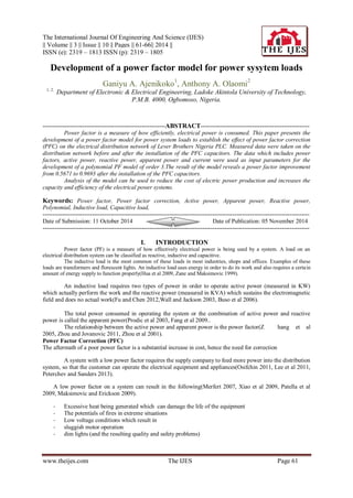
- 3. Development of a power factor model for power sysytem loads www.theijes.com The IJES Page 63 Discussion of results. Observation shows that before the power factor correction, the true power fluctuates as the time increases as displayed in Figure 1. At 06:00hours, the power was 178 Kw while at 20:00hours, it has fluctuated to 298 Kw. Figure 2 shows the variation of the apparent power with time. The apparent power increases gradually from 234 kVA to 433 kVA within the first 06:00hours while it declines gradually to 302 kVA within the next 18:00hours. The linear relationship between the power factor and the time before the power factor correction is displayed in Figure 3. The power factor increases gradually as the time progresses. At the end of the time, the power factor of the system loads has increased drastically to 0.8377. Figure 4 illustrates the correlation between the reactive power and time. The reactive power fluctuates rapidly as the time progresses, while Figure 5 shows how the current of the system loads increases in the first 06:00hours as the time progresses. The current drops to 529A at 12:00hours and remains constant until after 14:00hours before it starts fluctuating as the time progresses before the power factor correction. Figure 6 shows that after the power factor correction, the active power increases with time. The relationship between the apparent power and the time is displayed in Figure 7. The apparent power increases from 190 kVA at 06:00hours to 339 kVA in 10:00hours and drops gradually to 309 kVA after 12:00hours and thereafter fluctuates as the time progresses after the installation of the power factor corrector.. The power factor decreases from 0.9388 at 06:00hours to 0.9317 at 24:00hours while it increases gradually again to 0.9693 after the next 04:00hours as displayed in Figure 8. Figure 9 shows that after the power factor has been corrected, the reactive power fluctuates throughout as the time progresses while the current equally fluctuates with increase in time even though it becomes static after the 16:00hours for the next 02:00hours at 391A. Figure 10 shows the variation of the system load currents with time after the power factor correction. From the relationship between the power factor of the system loads and time after the PFC is used, a polynomial power factor model of order 3 is developed for power system loads. The order of the polynomial increases as the level of PF corrective devices increases. 0 5 10 15 20 25 250 255 260 265 270 275 280 285 Time (Hours) P (kW) Before PFC Figure 1: Variation of True power with time before power factor correction. 0 5 10 15 20 25 310 320 330 340 350 360 370 380 Time (Hours) S (kVA) Before PFC Figure 2: Variation of the Apparent power with time before power factor correction.
- 4. Development of a power factor model for power sysytem loads www.theijes.com The IJES Page 64 0 5 10 15 20 25 0.75 0.76 0.77 0.78 0.79 0.8 0.81 0.82 0.83 Time (Hours) PF Before PFC Figure 3: Variation of the Power factor with time before power factor correction. 0 5 10 15 20 25 440 450 460 470 480 490 500 510 Time (Hours) I Before PFC Figure 4: Variation of Reactive power with time before power factor correction. 0 5 10 15 20 25 440 450 460 470 480 490 500 510 Time (Hours) I Before PFC Figure 5:Variation of the system load currents with time before power factor correction. 0 5 10 15 20 25 250 255 260 265 270 275 280 285 Time (Hours) P (kW) After PFC Figure 6: Variation of True power with time after power factor correction.
- 5. Development of a power factor model for power sysytem loads www.theijes.com The IJES Page 65 0 5 10 15 20 25 260 265 270 275 280 285 290 295 300 Time (Hours) S (kVA) After PFC Figure 7: Variation of the Apparent power with time after power factor correction. 0 5 10 15 20 25 0.93 0.935 0.94 0.945 0.95 0.955 0.96 0.965 0.97 0.975 Time (Hours) PF After PFC Figure 8: Variation of Power factor with time after power factor correction. 0 5 10 15 20 25 50 55 60 65 70 75 80 85 90 95 Time (Hours) Q After PFC Figure 9: Variation of Reactive Power with time after power factor correction. 0 5 10 15 20 25 330 340 350 360 370 380 390 400 410 Time (Hours) I After PFC Figure 10: Variation of the system load currents with time after power factor correction. CONCLUSION A power factor model has been developed for power system loads, It is a polynomial of order3. A field capacitor bank was connected to the incoming transformer for appropriate sizing. Relevant mathematical relations for the various loads were modelled using MATLAB to generate random variables as the input parameters before and after the power factor correction. The results of the model can be used for power factor improvement of the system loads.
- 6. Development of a power factor model for power sysytem loads www.theijes.com The IJES Page 66 REFERENCES [1]. Buso S, Mattavelli P, Rossetto L and Spiazzi G(2006):”Simple digital control improving dynamic performance of power factor preregulators,” IEEE Trans. Power Electronics, issue 5, Vol. 13, Pp. 814 –823. [2]. De- Gusseme K and.Melkebeek J.A(2002):“Design issues for digital control of boost power factor correction converters,” IEEE International Symposium on Industrial Electronics,Vol. 3, pp. 731 –736. [3]. Fu M and Chen O(2012):“A DSP based controller for power factor correction(PFC) in a rectifier circuit,” IEEE Applied Power Electronics Conference, Vol. 1, Pp. 144 –149. [4]. Feng Y.T, Tsai G.L andTzou Y.Y(2009):“Digital control of a single-stage single-switch flyback PFC AC/DC converter with fast dynamic response,” IEEE Power Electronics Specialists Conference, Vol. 2, Pp. 1251 –1256. [5]. Hua G, Leu C.S and Lee F.C(2009):“Novel zero-voltage-transition PWM converters,” IEEE Power Electronics Specialists Conference, Vol. 1, Pp. 55-61 [6]. Lee F.C, Barbosa X, Peng J, Zhang B,Yang R and Canales F(2011): “Topologies and design considerations for distributed power system applications,” Proceedings of the IEEE, issue 6,Vol. 89, Pp.939 –950 [7]. Malik R(2009):“The power system challenge-understanding the total picture,” IEEE Applied Power Electronics Conference Proceedings, Vol.2, Pp. 202-208. [8]. Merfert I.W(2007):“Stored-duty-ratio control for power factor correction,” IEEE Applied Power Electronics Conference, vol. 2, Pp. 1123 –1129. [9]. Maksimovic D and Erickson R(2005):“Universal-input, high-power-factor, boost doubler rectifier,” Applied Power Electronics Conference, 1995, vol.1, pp. 459 –465. [10]. Osifchin N(2011):“A telecommunication building/power infrastructure in a new era of public networking,” IEEE International Telecommunications Energy Conference, Pp.1-7. [11]. Peterchev A.V and Sanders S.R(2013):“Quantization resolution and limit cycling in digitally controlled PWM converters,” Power Electronics Specialists Conference, Vol 2, Pp. 465 –471. [12]. Prodic A, Maksimovic D and Erickson R(2012):“Digital controller chip set for Isolated DC power supply,” IEEE Applied Power Electronics Conference, Vol. 2, Pp. 866 –872. [13]. Patella, A. Prodic A. Zirger and D. Maksimovic R(2009):“High-frequency digital PWM controller IC for DC-DC converters,” IEEE Trans. Power Electronics, Vol.18, issue 1, Pp. 438 –446. [14]. Prodic A,Maksimovic D and Erickson R.W(2003):“Dead-zone digital controller for improved dynamic response of power factor preregulators,” IEEE Applied Power Electronics Conference, , Vol. 1, Pp. 382 –388. [15]. Prodic A, Chen J, Erickson R.W and Maksimovic D(2007):“Digitally controlled low-harmonic rectifier having fast dynamic responses,” IEEE Applied Power Electronics Conference, Vol. 1, Pp. 476 –482. [16]. Rajagopalan J,Cho J.G,Cho B.H and Lee F.C(2005):“High performance control of single-phase power factor correction circuits using discrete time domain control method,” IEEE Applied Power Electronics Conference,Vol. 2, Pp. 647 –653. [17]. Sivakumar S, Natarajan K and Gudelewicz R(1995):“Control of power factor correcting boost converter without instantaneous measurement of input current,” IEEE Trans. Power Electronics, Vol. 10, issue 4, Pp. 435 –445. [18]. Wall S and Jackson R(2003):“Fast controller design for practical power factor correction systems,” IEEE Annual Conf. Of Industry Electronics, Pp. 1027-1032. [19]. Xiao J, Peterchev A.V and Sanders S.R(2009):“Architecture and IC implementation of a digital VRM controller,” Power Electronics Specialists Conference, Vol. 1, Pp. 38 –47. [20]. Zhang,Y, Jiang F.C and Lee M.M(2005): "Single-phase three-level boost power factor correction converter," Applied Power Electronics Conference and Exposition, APEC '95, Vol. 1.. Pp. 434–439. [21]. Zhou C and Jovanovic M.M(2011):“Design trade-offs in continuous current-mode controlled boost power-factor correction circuits," International High Frequency Power Conversion (HFPC) Conf., Pp. 209-220. [22]. Zumel, A, Garcia O, Riesgo T and Uceda J(2001):“A simple digital hardware to control a PFC converter,” IEEE Annual Conf. Industrial Electronics Society, Vol. 2, Pp. 943 –948. [23]. Zane R and Maksimovic D(1999):“A mixed-signal ASIC power-factor-correction(PFC) controller for high frequency switching rectifiers,” IEEE Power Electronics Specialists controller for high frequency switching rectifiers,” IEEE Power Electronics Specialists Conference, Vol. 1, Pp. 117 –122. [24]. Zhou J,Lu Y, Ren Z, Qian T and Wang Y(2001):“Novel sampling algorithm for DSP controlled 2 kW PFC converter,” IEEE Trans. Power Electronics, Vol. 16, Issue: 2, Pp. 217 –222.