1. Отчет за изпитване
Тестови сигнал-генератор
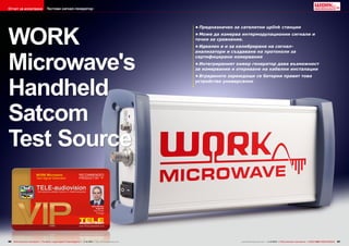
WORK
Microwave's
Handheld
Satcom
Test Source
96 TELE-audiovision International — The World‘s Largest Digital TV Trade Magazine — 1
1-12/2013 — www.TELE-audiovision.com
• Предназначен за сателитни uplink станции
• Може да измерва интермодулационни сигнали и
точки за сравнение.
• Идеален е и за калибриране на сигналанализатори и създаване на протоколи за
сертифицирани измервания
• Интегрираният sweep генератор дава възможност
за измервания и откриване на кабелни инсталации
• Вградените зареждащи се батерии правят това
устройство универсално
www.TELE-audiovision.com — 1
1-12/2013 — TELE-audiovision International — 全球发行量最大的数字电视杂志
97
2. TEST REPORT
Test Signal Generator
The Reference
Determines the Quality
In order to be able to measure complex analog systems, calibrate test equipment or test high-frequency
converters, you need to have
a test signal generator. This
device generates a signal
at a specific frequency and
power level where its precision is extremely critical
since it is to be used as a
reference signal.
WORK Microwave offers
exactly this kind of test signal generator; it can produce
signals from 50-180 MHz and
also from 950-2150 MHz.
The Handheld Satcom Test
Source is shipped in a suitable protective package in
which you‘ll find a red aluminum case, two USB cables
(A-B) and a power cable.
When you open up the
red aluminum case you‘ll
find in its padding the signal
generator, the power supply, a USB stick, the user
manual and a certificate of
conformance certifying that
the Handheld Satcom Test
Source complies with the
listed parameters. It is even
noted on the certificate that
any documentation that was
used in the manufacture of
this signal generator can
be made available upon request. This kind of documentation results in traceability;
all measured values can be
traced as far back as the
manufacturer WORK Microwave thereby precluding any
discussions on any measurement results.
Page 15 of the user manual
explains all of the functions
of the test signal generator
in a detailed yet easy-tounderstand format. The installation of the unit is quite
simple. You only need to run
the executable file from the
USB storage device. An actual installation is not necessary. Naturally, you can
also copy the program to the
hard drive.
The manufacturer was also
thoughtful enough to include
a copy of the user manual in
the USB storage device. Installing drivers is not necessary since Windows XP, Windows Vista and Windows 7
will recognize the instrument
as an HID (Human Interface
Device) and automatically
incorporate it into the operating system.
The Handheld Satcom Test
Source has an elongated
housing fabricated out of
aluminum. There‘s no doubt
that this is a robust test instrument that is further protected on the front and back
by hardened plastic. On the
front panel you‘ll find the
11-12/2013
WORK Microwave
Handheld Satcom Test Source
Allows for precise and certified
high-frequency measurements
www.TELE-audiovision.com/13/11/work-microwave
■ TELE-audiovision Editor Vitor
in action. It's not nearly as
difficult as it looks.
98 TELE-audiovision International — The World‘s Largest Digital TV Trade Magazine — 1
1-12/2013 — www.TELE-audiovision.com
www.TELE-audiovision.com — 1
1-12/2013 — TELE-audiovision International — 全球发行量最大的数字电视杂志
99
3. 1
power supply input (12V24V), two USB type B inputs
and three status LEDs. The
first LED indicates the instruments operational status (OK or error), the second
LED shows the charging status of the rechargeable battery and the third one shows
the system status.
The two USB inputs have
different functions. USB1
serves as an additional
source of power and also
provides for the data communication with the PC.
USB2 is exclusively used to
provide power to the unit if
for some reason the external
power supply can‘t be used.
The Handheld Satcom Test
Source runs from an internal
rechargeable battery that
lets you use it without having to keep it connected to
a power source. This is not
surprising considering this is
a portable signal generator.
It‘s also interesting that this
instrument can be operated
from a PC or laptop via the
USB ports and since a single
USB port cannot provide
enough power, the Handheld Satcom Test Source can
be connected to both USB
ports. Very clever!
On the back of the test
source is the on/off switch.
There‘s also a BNC jack that
provides a 10 MHz reference
output signal as well as an
SMA jack that provides the
signal generated by the test
source.
The signal generator also
provides a DC voltage on this
output which is indicated by
an additional LED. Control of
the unit is taken care of by a
Windows program which also
controls a sweep function.
Measurement
of High-frequency
Converters
The primary use of the
Handheld
Satcom
Test
Source is the measurement
of various parameters of
high-frequency (RF) converters. These RF converters, also available from
WORK Microwave, convert
the signal to be transmitted
from its original frequency to
a higher output frequency.
Since these high-frequency signals could not be routed through a satellite uplink
station between all the different devices (modulators,
multiplexers, etc.) using coaxial cable without incurring
some signal loss, waveguides
or very expensive cable are
needed. Instead, a different
path is used. The signal is
routed and processed in the
50 to 180 MHz range or the
950 to 2150 MHz range until
it‘s ready to be sent to the
uplink section. Only then, in
this final step, is the highfrequency converter used
to upconvert the signal into
the satellite uplink frequency
range.
Obviously, this high-frequency converter cannot
introduce any errors that
might interfere with a neighboring transponder or even
go as far as interfering with
normal satellite operation.
This kind of interference
is known as intermodulation. Intermodulation occurs
when two signals are modulated on two frequencies that
are very close to each other,
causing additional signal
peaks to appear on the sides
of the two main frequencies.
(see Figure 1).
To check and see how
much a high-frequency converter can minimize this Intermodulation effect, you
would need two RF test
sources so that you can
modulate two nearby signal
levels with known parameters. These two signal levels
would then be routed to the
high-frequency converters.
Using a spectrum analyzer,
you could then generate an
picture of this intermodulation.
It‘s exactly for this reason
2
1: Intermodulation occurs directly next to the wanted signal - see
the red labled signals
2: The compression point is defined to be at exactly 1 dB. From
here on the signal quality deviates from the ideal characteristic.
that WORK Microwave incorporated two independent
synthesizers in the Handheld
Satcom Test Source so that
now you can use just a single RF signal source to perform this measurement.
Obviously this greatly reduces the costs involved
in acquiring these RF test
sources since now you‘d only
need one of these instruments instead of two. At the
same time the test setup itself is simplified since only a
single cable and the upconverter need to be connected.
Another parameter that is
measured when it comes to
high-frequency converters is
the so-called 1 dB compression point. This measurement is used to check the
non-linear response of the
high-frequency
converter.
Here the amplitude of the input signal is slowly increased
100 TELE-audiovision International — The World‘s Largest Digital TV Trade Magazine — 1
1-12/2013 — www.TELE-audiovision.com
until the signal distortion
due to non-linearity deviates
exactly 1 dB from the ideal
characteristic curve (see
Figure 2).
The red line shows the
ideal output curve. Above a
specific input level the highfrequency converter begins
to distort the signal such
that a lower signal level is
available at the output hence the name “Compression“: a lower signal level is
at the output; the signal has
been compressed.
To be able to compare different devices, you measure
the input power level that
results in a 1 dB compression at the output. Here
the WORK Microwave Test
Source proves itself with the
ability to set the test signal
to any frequency from 50 to
180 MHz and 950 to 2150
MHz with a power level from
4. -45 dBm to -5 dBm in 0.5 dB
steps.
Another
parameter
to
check with high-frequency
converters is the conversion gain. Just like with the
measurement of the 1 dB
compression point, a signal
with a known signal level is
supplied to the converter.
A spectrum analyzer would
then be used to measure the
signal level at the output.
Of course, you could also
supply a real signal and
measure this. But due to
several factors this measurement would not be as
precise, that‘s why it‘s necessary to use a calibrated RF
test source.
In all of these applications
WORK Microwave has shown
that it has developed a fully
featured and well thought
out instrument: two independent synthesizers can
supply two signals simultaneously in order to measure
intermodulation.
1
6
4
2
The Handheld Satcom Test
Source‘s freely selectable
output level makes it possible to measure the 1 dB
compression point and also
gives you the ability to measure the conversion gain.
Handling the WORK Microwave Handheld Satcom Test
Source is further simplified
5
3
1. The application that controls the Handheld Satcom
test source is an easy to use tool which basically
consists of this main window. Thumbs up for the nice
graphical scheme, that perfectly explains what each
parameter and button is used for.
2. First you need to connect the software with the
Test Source. This takes exactly 5 seconds and both
Windows XP and Windows 7 did install the instrument
automatically without the need to provide any drivers.
3. Once the instrument is connected, the status in the
upper part of the window is updated. In this case, the
power is provided through two USB cables.
4. The sweep generator opens in a separate window
and allows users to specify frequency range, the up
and down increment and speed, as well as the pause
between sweeps.
5. It is of course possible to use the Handheld Satcom
Test Source without a connected laptop. You just
need to set up the desired parameters and store them
in the instrument. When you then turn it on, it will use
these parameters automatically. Great if you need to
measure several devices with the same input signal.
102 TELE-audiovision International — The World‘s Largest Digital TV Trade Magazine — 1
1-12/2013 — www.TELE-audiovision.com
5. by two additional details: a
rechargeable battery lets
you use the instrument for
hours at a time without being
1
connected to a power source
and since the test parameters can be stored in the unit
itself, no connection to a lap-
top is needed, for example,
when the conversion gain on
multiple units is measured.
Another plus is the BNC jack
4
Test Equipment
Calibration
on which a calibrated 10 MHz
signal is provided so that the
RF technology of different
devices can be controlled.
In the last issue of TELE-
5
audiovision we tested the
Deviser S7000 TV analyzer.
We were very impressed
with this analyzer; it comes
with every possible feature
that you could possibly want
in a TV tester and analyzer.
Even its measurement precision was able to go toe to toe
with our reference devices.
With the WORK Microwave Handheld Satcom Test
Source we wanted to know
for sure: how precise are
the Deviser S7000 measurements really?
The Handheld Satcom Test
Source’s output impedance
is specified at 50 Ohms while
the S7000 is at 75 Ohms as
is typical for TV applications.
Therefore an HP impedance
1. The Handheld Satcom
Test Source is configured
to generate a signal at 1000
MHz with -15 dBm and the
Deviser S7000 correctly shows
the signal at this frequency.
However, the units are shown
in dBµV as I forgot to configure
them properly.
2. Fortunately, the
Deviser S7000 allows the
measurements to be shown in
dBµV, dBmV or dBm. The latter
one is what I need.
3. And now the Deviser S7000
is showing the measurement
value of -16.5dBm. The
deviation of -1.5 dBm is not a
measurement error but rather
the effect of having too much
signal level on the cable I am
using.
4. Reducing the signal
output to -35 dBm on the test
source produces a readout of
-35.9 dBm. Excellent result,
considering these two devices
are manufactured at opposite
sides of the world.
5. The Handheld Satcom
Test Source can actually
output two different signals
simultaneously. Here I
configured one -35 dBm signal
at 1000 MHz and the other at
1100 MHz with -15 dBm.
Again, this signal level is
correctly identified and
confirmed by the Deviser
S7000. Simply brilliant.
2
■ The setup to test and evaluate the
WORK Microwave Handheld Satcom
Test Source. Notice the 50 Ohm to 75
Ohm impedance matching adapter from
HP. Tests confirmed the theory: in our
case the error was insignificant, so I
dispensed the use of the adapter.
3
104 TELE-audiovision International — The World‘s Largest Digital TV Trade Magazine — 1
1-12/2013 — www.TELE-audiovision.com
www.TELE-audiovision.com — 1
1-12/2013 — TELE-audiovision International — 全球发行量最大的数字电视杂志
105
6. 6
8
10
11
and is the result of the application of international standards in development and
production.
The pictures show the
measured values in the
ranges 50 to 180 MHz and
950 to 2150 MHz. These are
definitely within the precision range of the device and
the tolerance given in the
WORK Microwave Handheld
Satcom Test Source‘s certificate.
This shows that the Handheld Satcom Test Source
can be used in another outstanding way: it can be used
to precisely calibrate test
equipment.
Testing
a CATV Cable Run
7
converter
(part
number
08590-60090) designed for
the 1 MHz to 1.8 GHz range
6. Now for something
9
completely different. At 75
MHz a signal of -35 dBm is
generated and measured
with a deviation less
than 1 dBm. Absolutely
amazing.
7. Since the Deviser S7000
supports two markers
in CATV mode which is
used to measure the tilt
between two channels, I
generated one signal at 80
MHz with -35 dBm and a
second signal at 100 MHz
with -45 dBm. Incredibly,
the deviation was -0.1
dBm and -0.2 dBm,
respectively. The tilt was
measured with 9.9 dB.
8. To test the end of scale
I generated a signal at 2000 MHz with -15 dBm. Again the Deviser
S7000 measured this signal with an amazing precision.
9. To test the sweep generator several slop step intervals had to be
tested in order to allow the spectrum analyzer function to sample
enough data to correctly measure the signal.
10. With a slop step interval of 500 ms the Deviser S7000 produced
good results so I started the test run.
11. First I measured the whole spectrum with the MAX function
active. This way we can see the whole range at the end of the test.
The result is excellent with the spectrum oscillating about 3 dB
around -35 dBm, which is the output level setup on the Handheld
Satcom Test Source. This oscillation is an acceptable error and
due to the fact that I was giving the spectrum analyzer just about
the time to render the spectrum.
12. This picture shows the same output signal, but this time the
signal had to pass a multi switch and about 20 meter of cable, an
aerial socket and then another cable before reaching the spectrum
analyzer. Notice that only the upper curve is of interest. The result
is clear to see: there is an over attenuation of about 10 dB to 15 dB.
Also, it is clear to see that the attenuation is not uniform.
was used. This converter has
an attenuation of -15 dBm.
The
WORK
Microwave
Handheld
Satcom
Test
Source shows here that this
professional signal analyzer
106 TELE-audiovision International — The World‘s Largest Digital TV Trade Magazine — 1
1-12/2013 — www.TELE-audiovision.com
12
Another application for
the Handheld Satcom Test
Source is the testing of a
CATV network‘s cable installation. For this test we used
our own distribution network
here in the TELE-audiovision
test center.
A multiswitch with 16 inputs for the satellite range
(950 - 2150 MHZ) and another input for terrestrial
TV (50 - 850 MHz) was used
for distribution. The signal
is then made available on
eight outputs and distributed throughout the house to
a number of antenna ports
that each provide separate
satellite and CATV outputs.
The next step was to measure the attenuation of the
signals in the satellite range,
but we also wanted to know
if the multiswitch, the coax
cable and the antenna jacks
had more of an affect on
some frequencies than on
others.
Normally, you’d use a
noise generator for this task
but they typically don’t come
with the same measurement
precision as does the Handheld Satcom Test Source.
If you’re thinking now
that it would be an enormous amount of work in that
you’d have to check each
frequency individually, you’d
be wrong. WORK Microwave
incorporated a sweep generator in the Handheld Satcom Test Source that can be
set to run through a userdefined frequency range (50
to 180 MHz and 950 to 2150
MHz). The frequency steps
can also be set (minimum of
0.5 MHz) as well as the desired speed (starting at 10
ms per step).
The output level can be
set from -5 to -45 dBm. The
sweep itself can be run bidirectionally: when the sweep
reaches the upper frequency limit, it turns around
can perform measurements
with a deviation of less than
1 dB. This is extremely low
www.TELE-audiovision.com — 1
1-12/2013 — TELE-audiovision International — 全球发行量最大的数字电视杂志
107
7. and goes back the other
way whereby the frequency steps (MHz) and sweep
speed (ms) can be set up
separately. You can also set
up a pause between the two
sweeps.
The Handheld Satcom
Test Source was connected
to the input of the multiswitch which would then
operate the switch using
the frequency sweep generator. The spectrum analyzer mode was activated
on the test equipment and
it was used with the peaklevel hold function activated
in order to be able to read
the results of the frequency
sweeps across the entire
frequency range.
The first attempt failed
because we didn‘t realize
that the spectrum analyzer
needs a certain sampling
period to be able to generate a spectrum from the signal. If the signal generator
sweep is too fast, it doesn‘t
allow enough time for the
analyzer to correctly measure the signal.
So we first had to directly
connect the signal generator
to the analyzer and try a few
different scenarios to determine the correct parameters
for the frequency sweep.
It quickly became clear
why WORK Microwave incorporated so many parameters in the Handheld Sat-
■ Setup to measure the
attenuation and other
problems in our SAT and
CATV distribution system.
Luckily, the Handheld Satcom
Test Source works on battery.
108 TELE-audiovision International — The World‘s Largest Digital TV Trade Magazine — 1
1-12/2013 — www.TELE-audiovision.com
8. 1
5
2
1. Testing the DVB-T USB dongle with SDR# at 50
MHz. The signal is clean and correctly tuned on the
supposed frequency.
2. Same test, but now on 120 MHz. This frequency
band is used for air control communications and it is
good to see that the DVB-T USB dongle behaves very
well here.
3. At 180 MHz the reception is acceptable, albeit
the gain is lower. The indicated dB value is just a
reference as the RTL2832U chip and the FC0012 tuner
have automatic gain control activated.
4. Unfortunately my DVB-T USB dongle has the FC0012
tuner instead of the much better E4000 one. The result
is a total deafness at 950 MHz.
5. As expected, no signal at 1200 MHz, either.
6. At 118 MHz frequent radio communications between
pilot and tower can be heard as the test centre is
located near the local airport. Using the Handheld
Satcom Test Source I can be sure that my DVB-T USB
dongle is capable of tuning and demodulating this
frequency.
7. I did not have to wait long to get to hear a pilot
reporting to the tower. Notice the small red line
at 118.000 MHz in the waterfall graph. It suddenly
appears with the communication and lasts only a few
seconds. This kind of air traffic communication is
naturally modulated in AM and it is incredible that a
DVB-T USB receiver for less than 20 Euro can actually
be used as a SDR radio scanner to receive such
communications.
3
4
com Test Source: they really
are all necessary and useful.
The desired measurement
was taken with the following
parameters:
- Start frequency: 950 MHz
- End frequency: 2150MHz
- Frequency step: 1 MHz
- Time interval per step:
500 ms
- Signal level: -35 dBm
These values allowed the
analysis of the entire satellite frequency range and the
fluctuations in the directly
110 TELE-audiovision International — The World‘s Largest Digital TV Trade Magazine — 1
1-12/2013 — www.TELE-audiovision.com
connected analyzer turned
out to be approximately +/3 dBm.
Since the WORK Microwave Handheld Satcom Test
Source is a portable unit with
built-in rechargeable batteries, it was easy to transport
it to the switch box and then
put it to work. It was simply
connected to a Netbook and
operated without a power
connection.
The built-in rechargeable
batteries in the signal generator let you operate with a
laptop for longer periods of
time without a power connection since the signal generator won’t suck the laptop
battery dry if you don’t use
both of the USB connections
on the Handheld Satcom
Test Source (the second USB
connection serves exclusively to recharge the battery).
The measurement of the
complete
spectrum
with
these parameters needed
about five minutes. During this time you could con-
6
7
fidently
focus
your attention on
something
else
because if the
test is longer, the
measurements
would simply be repeated
continuously.
The results of these measurements show that there‘s
a signal attenuation of 10
dB to 15 dB through the
signal distribution system.
These are overall good values considering that there’s
over 20 meters of cable, a
multiswitch, an antenna jack
and some more cable between the Handheld Satcom
Test Source and the Deviser
S7000.
But this measurement
does point out a rather annoying aspect of this setup:
the signal attenuation is not
constant across the entire
frequency range, but rather,
some frequency segments
are more strongly attenuated than others.
There‘s no question: the
WORK Microwave Handheld
Satcom Test Source makes
it possible for an installer
to check out an installation
before the actual signals are
sent through it while at the
same time the quality of the
system can be confidently
verified using a certified reference signal.
The emphasis here is on
“certified” and “reference”:
with the Handheld Satcom
Test Source there are no
longer any discussions about
error tolerances.
Testing
an SDR Receiver
We even stumbled across
an unusual application for
the Handheld Satcom Test
Source: the DVB-T COFDM
demodulator built in to many
USB DVB-T receivers, the
Realtek RTL2832U, can also
be used for radio reception
because this chip makes
available the raw I/Q samples.
The thought here was to
be able to demodulate DAB,
www.TELE-audiovision.com — 1
1-12/2013 — TELE-audiovision International — 全球发行量最大的数字电视杂志
111
9. DAB+ and FM yet with the
matching drivers you can
also use USB DVB-T receivers with Software Defined
Radio (SDR); using special
SDR software like SDR# you
get a real scanner radio with
which for example you could
tune into air traffic control.
The problem though is
the built-in tuner in the
USB DVB-T receiver. Differ-
ent chips are used here, for
example, the FC0012 and
FC0013 models. One of the
USB receivers in our test
center has the FC0012 tuner.
Unfortunately, these tuners are limited to the 50 to
950 MHz frequency range
but it‘s the 117 to 137 MHz
aircraft band that‘s especially interesting. Our test center was thus outfitted with a
proper antenna and using an
Icom R3 we could listen in to
the aircraft band.
Since there aren‘t continuous transmissions on these
frequencies and since I wanted to more closely analyze
the sensitivity and reception
capabilities of the USB receiver, it was once again time
to put the Handheld Satcom
Test Source to work.
The test setup was extremely simple: the USB
DVB-T receiver was connected to a PC and installed with
the special SDR drivers that
can be found in the Internet under the name ”Zadig“.
112 TELE-audiovision International — The World‘s Largest Digital TV Trade Magazine — 1
1-12/2013 — www.TELE-audiovision.com
This freely available SDR#
software was automatically
recognized by the USB receiver with its RT-L2832U
chips and just like that the
signal can be displayed on
the PC as a spectrum. Demodulation takes place in
the modulations typical for
a scanner radio: AM, FM, CW
etc., whereby the bandwidth
can be individually set.
On the Handheld Satcom
Test Source a variety of frequencies were tried between
50 and 180 MHz with emphasis on frequencies from 117
to 137 MHz.
The results can be seen in
the pictures and vary from
spectacular to disappointing.
The resolution of the signal
displayed by the Handheld
Satcom Test Source was excellent. In the aircraft frequency band it appeared
that the USB DVB-T receiver would be able to provide
a usable signal so the next
step was to connect it to
the outdoor antenna. Sure
enough, after only a few
minutes an aircraft could be
heard making an approach
to an airport.
The disappointment came
about because the USB DVBT receiver in no way could
receive this popular frequency band correctly. The
signal from the Handheld
10. expert
OPINION
WORK Microwave
Test Signal Generator
RECOMMENDED
PRODUCT BY
Vitor Martins
Augusto
Test Center
Portugal
+ ● Compact and portable test source
● Two synthesizers for simultaneous generation of two signals
● Configurable sweep generator
● Extremely high accuracy
● Provided with compliance certificate, containing detailed
information about the instruments precision
● Easy to use software, no installation required
● No driver installation required, device recognized by Windows as Human Input Device
● Internal battery
– ● Parameters have to be confirmed with ENTER key
● Sweep Modus does not show current Frequency
TECHNICAL
DATA
Manufacturer
WORK Microwave, Germany
Tel.
+ 49-8024-6408-27
Internet www.work-microwave.de
Satcom Test Source was
also received on the wrong
frequencies;
this
clearly
shows a problem with the
DVB-T tuner. Above 950 MHz
that FC0012 tuner was sure
enough not able to receive
any kind of usable signal
even though these frequencies could easily be entered.
Conclusion
Even though the manufacturer only suggests using
the test source to test highfrequency converters, it can
also be used in many other
applications. When you‘re
dealing with test equipment
calibration, problems due to
interference signals or locating the source of unwanted
signal attenuation, such a
test signal source would be
worth every penny. You can
directly measure what‘s going on with a known signal.
We were very impressed
by the unbelievable precision of the Handheld Satcom
Test Source. Together with
its certificate, it would be the
perfect tool for smaller operations to verify the precision
of their test equipment, calibrate them and create certified protocols that would
withstand any kind of scrutiny.
WORK Microwave, with
their Handheld Satcom Test
Source, has developed an
unusual instrument designed
specifically for use by technicians. Instead of a large and
heavy instrument chained to
an electric power cord, you
have a compact, portable
unit that you can hold in your
hands and that runs on rechargeable batteries. It‘s a
device that will quickly become part of many different
operations.
Model
RF Signal Generator
Frequency range
50 MHz to 180 MHz and 950 MHz to 2150 MHz
Frequency resolution
0.5 MHz
Output level
-45 dBm to -5 dBm
Output level resolution
0.5 dB
Level tolerance
± 1 dB
Output impedance
50 Ohm
Output mute
< -60 dBc
Reference Output
10 MHz, -10 dBm to +10 dBm, 0.5 dB steps
Temperature range
0°C to +50°C
Interface
USB 2.0
Power supply
ext. 24 V DC, USB, internal Battery
Power consumption
max. 12 W
Connectors
RF out: 50 Ohm SMA female
REF out: 50 Ohm BNC-female
USB 2.0: USB Standard type B
Weight
1.5 kg
Dimensions (L x W x H)
250 x 125 x 74 mm
114 TELE-audiovision International — The World‘s Largest Digital TV Trade Magazine — 1
1-12/2013 — www.TELE-audiovision.com