EU Funded CE RFID Workpackage
•
0 likes•30 views

Covering state of the art RFID advancements. Skandsoft in middleware category along with 2 others, including IBM.

Recommended
Recommended
More Related Content
Similar to EU Funded CE RFID Workpackage
Similar to EU Funded CE RFID Workpackage (20)
More from Surendra Kancherla
More from Surendra Kancherla (16)
Recently uploaded
Recently uploaded (20)
EU Funded CE RFID Workpackage
- 1. WP1 – Roadmap Working Draft 1.3, Final Report Dr. Leif Wiebking Gerhard Metz Siemens AG Miia Korpela Mikko Nikkanen Dr. Katariina Penttilä UPM Raflatac February 18, 2007
- 2. 2 Document History Version Date Author Chapter Remarks V1.0 12.9.2007 G. Metz All Initial version V1.1 4.12.2007 G. Metz All Revised version after considering Comment Matrix CE RFID WP1 from coordinator/secretariat, step 2 V1.2 18.1.2008 VDI/VDE-IT All Layout. Proofreading V1.3 18.2.2008 G. Metz All Review, Minor Changes, Comments from UPM Raflatac included Table 1 Document history
- 3. 3 Executive Summary The coordination action CE RFID funded by the European Union is divided into eight work packages. This is the final report of work package 1 entitled “RFID Roadmap”. Objectives of work package 1: RFID roadmap The work package should give a clear overview of the actual state-of-the-art of RFID technology and its future developments in order to gain a more objec- tive discussion on RFID. Although the coordination action considers the impor- tance of passive RFID technology for the use in mass market applications like retail and logistics, RFID is seen as a broad area of technologies with different physical properties and limits. Users, legislation bodies, citizens, and NGOs are often not aware of the basic technology conditions of RFID which might result in a misunderstanding of the benefits, costs, and risks of RFID. Fre- quently, properties of different RFID technologies are combined incorrectly (e.g. low cost 5-cent-tag and reading ranges up to 100 metres), leading to wrong expectations of RFID performance. Work Package 1 presents a basic overview of the RFID technologies currently available on the market together with their specifications. It investigates ma- jor international R&D activities that have been published so far with respect to RFID and tries to identify pre-sent gaps and bottlenecks that still remain to be solved in order to support broad implementation of RFID technologies. Based on the findings, a timeline of future RFID developments and a possible RFID roadmap will be outlined. The coordination action CE RFID also benefits from the roadmap of the European technology platform “European Technology Platform on Smart Systems Integration” (EPoSS) outlined in its Strategic Re- search Agenda (SRA). Objectives of this final report Based on a decision of the project consortium this final report contains all in- formation previously collected in draft versions of intermediate reports. There- fore, the objectives of this document are identical to the work package objec- tives (see above). The three main topics of work package 1 are: RFID technologies — state-of-the-art RFID technologies — international R&D activities RFID technologies — bottlenecks and R&D approaches
- 4. 4 Results and recommendations to the stakeholders Europe has a strong position within the RFID market. In the low frequency (LF) and high frequency (HF) technology areas Europe currently takes the leading position (2007). In the ultra-high frequency (UHF) sector many retail companies make progress in the rollout of most recent RFID technology (Class 1 Generation 2, short: Gen 2) for the supply chain management (full rollout is expected in 2008). On a first step pallets and cases will be tagged. “Gen 2” tags provide a “kill-command” feature that allows to permanently disable the tag after usage (e.g. at the point of sale (POS)), addressing pri- vacy issues of consumers carrying those tags. Other upcoming application fields are: RFID and anti-theft systems, Food monitoring (cool chain), elec- tronic goods, asset management, access control, tracking and tracing, ticket- ing, and industrial applications (production, automation, manufacturing, proc- ess control). Although there are many systems and different RFID technologies available on the market, there is still room for R&D in the industry as well as in acade- mia in order to overcome remaining technological bottlenecks. There are hardware related recommendations (e.g. improved on-metal-tags, ultra-low power tags, packaging and mounting, printable electronics, sensor applica- tions, multi-frequency/multi-standard readers, low-cost manufacturing, local- isation, new materials/robustness, tags with displays, environmentally com- patible tags, system on chip), application related recommendations (e.g. sen- sor networks, reading rates near 100%, “last mile” support, new applications, market studies), network/software/systems related recommendations (e.g. plug and play infrastructure, Internet of Things, international ONS, data proc- essing/networks, standard interfaces, smart systems), standards/regulations related recommendations (e.g. UHF harmonisation, harmonised EU regula- tions, vendor interoperability, peer-review encryption techniques, fallback procedures), and data security/data protection/privacy related recommenda- tions (e.g. privacy by design, increasing public acceptance, information, kill- tag-feature, prevent unnoticed tag reading, network data security).
- 5. 5 Table of Contents 1 Approach .............................................................................. 18 1.1 Definition of work package topic ............................................... 18 1.2 Structure of work package topics.............................................. 19 1.2.1 RFID technologies — state-of-the-art ........................................ 19 1.2.2 RFID Technologies – international R&D activities......................... 20 1.2.3 RFID Technologies – bottlenecks and R&D approaches................. 20 1.3 Relevant stakeholders............................................................. 21 1.3.1 Stakeholder group “Research & Development”............................ 21 1.3.2 Stakeholder group “RFID technology suppliers”........................... 22 1.3.3 Stakeholder group “business associations” ................................. 24 1.3.4 Stakeholder group “government & governmental institutions”....... 25 1.3.5 Stakeholder group “standardisation organisations” ...................... 25 1.3.6 Stakeholder group “quasi-autonomous and non-governmental organisations”........................................................................ 25 1.3.7 Stakeholder group “RFID end user companies” ........................... 26 1.3.8 Contribution .......................................................................... 26 2 Methodology.......................................................................... 28 2.1 Assessment criteria ................................................................ 28 2.2 Methods................................................................................ 29 3 State-of-the-art and Analysis ................................................... 32 4 Application View..................................................................... 33 4.1 RFID vs. barcode and OCR....................................................... 33 4.1.1 Mapping to the reference model ............................................... 35 4.2 RFID Reference Model............................................................. 37 4.3 Application examples .............................................................. 40 4.3.1 Logistics, supply chain management at Metro Group.................... 40 4.3.2 Identity management, security, access control ........................... 41 4.3.3 Contactless smart card “Mifare”................................................ 41
- 6. 6 4.3.4 Contactless smart card “FeliCa” ................................................43 4.3.5 µ-chip ...................................................................................44 4.3.6 Animal identification................................................................45 4.3.7 Automation, production management, manufacturing ..................45 4.3.8 Automotive ............................................................................46 4.3.9 Smart drug cabinet .................................................................46 4.3.10 Medical, pharmaceutical, health care .........................................46 4.3.11 VeriChip ................................................................................47 4.4 Niche applications ...................................................................47 4.4.1 Tree identification ...................................................................48 4.4.2 Identification of bees...............................................................48 4.4.3 Railroad car identification.........................................................48 4.5 Mapping to the reference model................................................49 5 Transponder Classes View ........................................................51 5.1 EPCglobal classes....................................................................51 5.1.1 Passive tags...........................................................................52 5.1.2 Semi-passive tags...................................................................53 5.1.3 Active tags.............................................................................53 5.1.4 Mapping to the reference model................................................54 6 ISO/OSI Network Model View ...................................................57 6.1 Tag/reader interface................................................................60 6.2 Reader/edge server interface....................................................64 6.3 Edge server/integration server interface.....................................65 6.4 Integration server/integration server interface ............................67 6.5 Mapping to the reference model................................................68 7 Technological View..................................................................71 7.1 Air interfaces..........................................................................71 7.1.1 Inductive coupling...................................................................71 7.1.2 Electromagnetic field coupling...................................................73 7.1.3 Mapping to the reference model................................................81
- 7. 7 7.2 Reader technology.................................................................. 85 7.2.1 Mapping to the reference model ............................................... 89 7.3 Antenna arrangements............................................................ 92 7.4 Transponder technology .......................................................... 93 7.4.1 Mapping to the reference model ............................................... 94 7.4.2 Performance .......................................................................... 96 7.4.3 Manufacturing...................................................................... 102 7.4.4 Antenna designs................................................................... 106 7.4.5 Low power designs ............................................................... 111 7.5 RFID middleware systems ..................................................... 114 7.5.1 Hardware ............................................................................ 114 7.5.2 Software ............................................................................. 116 7.6 Backend systems ................................................................. 119 7.6.1 Mapping to the reference model ............................................. 121 7.7 Advanced systems................................................................ 122 7.7.1 Sensors .............................................................................. 122 7.7.2 Localisation ......................................................................... 123 7.7.3 Ambient intelligence ............................................................. 125 7.7.4 Networks ............................................................................ 125 7.7.5 Robust systems.................................................................... 128 7.7.6 Mapping to the reference model ............................................. 130 8 Standards and Regulations View............................................. 134 8.1 Radio regulations ................................................................. 134 8.1.1 Mapping to the reference model ............................................. 137 8.2 Air interface standards .......................................................... 139 8.3 Application standards............................................................ 141 8.4 Standards for test methods.................................................... 143 8.5 Data management standards ................................................. 143 8.6 Data structure standards....................................................... 144 8.7 Sensor standards ................................................................. 145
- 8. 8 8.8 Mapping to the reference model.............................................. 145 9 Data Processing View ............................................................ 148 9.1 Data security, data protection, data privacy.............................. 149 9.1.1 Security threats.................................................................... 149 9.2 Addressing data protection and privacy concerns....................... 157 9.3 Safety-related issues............................................................. 158 9.3.1 Physical threats .................................................................... 159 9.4 Secure RFID systems ............................................................ 160 9.5 Mapping to the reference model.............................................. 166 10 Market View......................................................................... 169 10.1 Vendors of RFID equipment.................................................... 170 10.1.1 RFID vendors by countries and continents ................................ 170 10.1.2 RFID vendors by frequency .................................................... 171 10.1.3 RFID vendors by standards .................................................... 176 10.1.4 RFID systems by tag power supply.......................................... 176 10.1.5 RFID vendors by applications.................................................. 177 10.2 System specifications and properties ....................................... 178 11 Intellectual Property View ...................................................... 181 11.1 Patents, utility patents........................................................... 181 11.2 Patent pools......................................................................... 186 12 RFID Technologies – International R&D Activities....................... 189 12.1 Introduction......................................................................... 189 12.2 Sources of international R&D activities ..................................... 189 12.3 R&D Database ...................................................................... 190 12.4 Technology aspects............................................................... 191 12.4.1 Transponder technology......................................................... 191 12.4.2 Interrogator technology ......................................................... 204 12.4.3 System technology................................................................ 208 12.5 Application specific topics....................................................... 211 12.5.1 Fraunhofer Institutes (Germany)............................................. 211
- 9. 9 12.5.2 LogMotionLab ...................................................................... 212 12.5.3 openID-center ..................................................................... 212 12.5.4 Ko-RFID.............................................................................. 212 12.5.5 Flog – LogIDLab................................................................... 213 12.5.6 Sokymat Automotive ............................................................ 213 12.5.7 Identec Solutions ................................................................. 214 12.5.8 Philips/NXP.......................................................................... 214 12.5.9 Plefo Ab / Mannings.............................................................. 214 12.5.10 Philips Semiconductors / Graz University of Technology ............. 215 12.5.11 Traffic Supervision Systems A/S ............................................. 215 12.5.12 Immotec Systems / Homenet................................................. 215 12.5.13 Eczacibasi Bilisim ................................................................. 216 12.5.14 Internic Data Communications GmbH / Smart-ID...................... 216 12.5.15 EOSS Innovation Management ............................................... 216 12.5.16 Follow Me............................................................................ 216 12.5.17 Mapping to the reference model ............................................. 216 12.6 Software, systems, and networks ........................................... 219 12.6.1 RFID middleware.................................................................. 219 12.6.2 Software, Systems and networks............................................ 222 12.7 Socio-economic aspects ........................................................ 236 12.7.1 Security, data protection, privacy ........................................... 237 12.7.2 Environmental and safety aspects........................................... 240 12.7.3 General aspects ................................................................... 241 12.7.4 Mapping to the reference model ............................................. 242 13 RFID Technology Bottlenecks and R&D Approaches ................... 245 13.1 Introduction ........................................................................ 245 13.2 Technology aspects .............................................................. 245 13.2.1 Transponder technology ........................................................ 245 13.2.2 Interrogator technology ........................................................ 265 13.2.3 System technology ............................................................... 269
- 10. 10 13.3 Application specific topics....................................................... 274 13.3.1 The real-time-enterprise ........................................................ 274 13.3.2 Standardisation of application layers........................................ 274 13.3.3 Traffic control and safety aspects ............................................ 275 13.3.4 Pairing objects...................................................................... 275 13.3.5 Improving of medication compliance........................................ 275 13.3.6 Supporting blind people ......................................................... 276 13.3.7 Anti-counterfeiting, RFID for DRM ........................................... 276 13.3.8 Support of pilot operations ..................................................... 276 13.3.9 E-tax-free with RFID ............................................................. 277 13.3.10 Market studies...................................................................... 277 13.3.11 Mapping to the reference model.............................................. 277 13.4 Software, systems, and networks............................................ 279 13.4.1 Internet of Things ................................................................. 279 13.5 Socio-economic aspects ......................................................... 279 13.5.1 Trust and acceptance ............................................................ 280 13.5.2 Security, data protection, privacy............................................ 280 13.5.3 Environmental and safety aspects ........................................... 281 13.5.4 Mapping to the reference model.............................................. 281 14 RFID technology roadmap ...................................................... 284 14.1 Introduction......................................................................... 284 14.2 EPCglobal roadmap ............................................................... 285 14.3 CE RFID roadmap ................................................................. 289 14.3.1 Packaging............................................................................ 289 14.3.2 Chip design.......................................................................... 290 14.3.3 Energy aspects..................................................................... 290 14.3.4 RF technology ...................................................................... 291 14.3.5 Manufacturing ...................................................................... 292 14.3.6 Systems .............................................................................. 293 14.3.7 Readers/interrogators............................................................ 294
- 11. 11 14.3.8 Non-silicon technologies ........................................................ 296 14.3.9 Bi-stable displays ................................................................. 297 14.3.10 Sensors .............................................................................. 297 14.3.11 Cryptography....................................................................... 298 14.3.12 ICT architectures.................................................................. 298 14.3.13 Socio-economic aspects ........................................................ 299 15 Conclusions ......................................................................... 301 15.1 Summary............................................................................ 301 15.2 Recommendations ................................................................ 311 16 References .......................................................................... 323 17 Appendices.......................................................................... 330 17.1 RFID vendor list ................................................................... 330 17.2 International RFID R&D activities............................................ 330 17.3 RFID research roadmap for all topics....................................... 330 17.4 RFID stakeholder model ........................................................ 334 17.5 RFID Reference Model........................................................... 335
- 12. 12 List of Figures Figure 1 RFID applications ...............................................................35 Figure 2 Passive and robust RFID systems for identification of railroad cars ......................................................................49 Figure 3 RFID system block diagram .................................................57 Figure 4 Communication reader to tag...............................................61 Figure 5 Communication tag to reader, reader talks first ......................62 Figure 6 Inductive coupling (physical principle for radio frequencies below 40 MHz)...................................................................72 Figure 7 Example for communication tag to reader with Manchester coded binary data ..............................................................73 Figure 8 Electromagnetic field coupling (physical principle for radio frequencies above 40 MHz)..................................................74 Figure 9 Comparison of receiving level at a transponder between magnetic field coupling and electromagnetic field coupling .......76 Figure 10 Different field distribution of magnetic field (left) and electro magnetic field (right)..........................................................77 Figure 11 Tendencies of system capabilities .........................................78 Figure 12 Effects that affect communication quality...............................79 Figure 13 RFID networking ................................................................85 Figure 14 Function blocks that are integrated into most RFID readers ......87 Figure 15 Typical block diagram of a transponder. Not all blocks need to be present.....................................................................94 Figure 16 Dependency of performance parameters of transponders on their physical properties......................................................97 Figure 17 Assembly / chip attachment............................................... 104 Figure 18 Assembly / lamination ...................................................... 104 Figure 19 Top left: Mifare card with coil antenna and chip; bottom: miscellaneous coil antennae; ISO 15 693: 13.56 MHz vicinity; .......................................................................... 107 Figure 20 Top: dipole antenna; bottom: miscellaneous tag antennae layouts; UHF; .................................................................. 108 Figure 21 Block diagram of circuit for energy harvesting ...................... 112
- 13. 13 Figure 22 Tendencies for supply voltage and power efficiency for CMOS circuits.................................................................. 113 Figure 23 Central and de-central RFID middleware approach................ 115 Figure 24 In the case of localisation systems the concepts of sensor fusion offer impressively enhanced results........................... 123 Figure 25 Localisation enabled services in future RFID applications ....... 124 Figure 26 RFID localisation with active tags: the reader is able not only to read the tag’s ID and data, but can also locate the tag and provide the tag’s coordinates. ................................ 124 Figure 27 Smart home enabled by RFID sensor networks .................... 125 Figure 28 Wireless sensor networks: what is important?...................... 126 Figure 29 Application area for RFID networks: the origin of a fire is detected and the information is transmitted via the network. also the position of the automated fire fighting system is estimated by the network ................................................. 127 Figure 30 SAW identification system process ..................................... 129 Figure 31 Main international RFID standards...................................... 140 Figure 32 ISO standards hierarchy for logistic units ............................ 142 Figure 33 The architecture of the MIFARE tag .................................... 161 Figure 34 MIFARE tag and reader..................................................... 161 Figure 35 RFID plaintext communication cloning............................. 162 Figure 36 Symmetric authentication ................................................. 163 Figure 37 Asymmetric authentication................................................ 164 Figure 38 RFID vendors by countries ................................................ 170 Figure 39 RFID vendors by continent ................................................ 171 Figure 40 LF RFID suppliers by continent........................................... 172 Figure 41 HF RFID suppliers by continent .......................................... 172 Figure 42 UHF RFID suppliers by continent ........................................ 173 Figure 43 RFID vendors by frequency ............................................... 173 Figure 44 RFID vendors by frequency range ...................................... 175 Figure 45 RFID systems by standards ............................................... 176 Figure 46 RFID systems by tag power supply..................................... 176 Figure 47 RFID systems by applications ............................................ 177
- 14. 14 Figure 48 Short, mid and long term R&D timeframe for RFID packaging ....................................................................... 289 Figure 49 Short, mid and long term R&D timeframe for chip design ....... 290 Figure 50 Short, mid and long term R&D timeframe for RFID energy aspects........................................................................... 291 Figure 51 Short, mid and long term R&D timeframe for RFID RF technology ...................................................................... 292 Figure 52 Short, mid and long term R&D timeframe for RFID manufacturing ................................................................. 293 Figure 53 Short, mid and long term R&D timeframe for RFID systems.... 294 Figure 54 Short, mid and long term R&D timeframe for RFID readers / interrogators ................................................................... 295 Figure 55 Short, mid and long term R&D timeframe for RFID non- silicon technologies........................................................... 297 Figure 56 Short, mid and long term R&D timeframe for RFID bi-stable displays .......................................................................... 297 Figure 57 Short, mid and long term R&D timeframe for RFID sensors .... 298 Figure 58 Short, mid and long term R&D timeframe for RFID cryptography................................................................... 298 Figure 59 Short, mid and long term R&D timeframe for RFID ICT architectures ................................................................... 299 Figure 60 Short, mid and long term R&D timeframe for RFID socio- economic aspects............................................................. 300 Figure 61 Diagram of the CE RFID stakeholder model.......................... 334
- 15. 15 List of Tables Table 1 Document history ................................................................ 2 Table 2 Table of RFID views ........................................................... 32 Table 3 Overview application characteristics, used frequencies, typical applications ............................................................ 33 Table 4 Benefits and disadvantages of barcode / OCR ........................ 34 Table 5 Benefits and disadvantages of RFID...................................... 34 Table 6 Mapping auto-id technologies to reference model ................... 36 Table 7 CE RFID Reference Model main categories............................. 38 Table 8 Subcategories covered by work package 1............................. 39 Table 9 Mapping application examples to reference model .................. 50 Table 10 EPCglobal RFID technology classes....................................... 51 Table 11 Mapping basic transponder classes to reference model ............ 55 Table 12 ISO/OSI layer model .......................................................... 58 Table 13 Mapping network model to reference model........................... 69 Table 14 RFID air interfaces ............................................................. 71 Table 15 Advantages and disadvantages of inductive coupling............... 73 Table 16 Advantages and disadvantages of electromagnetic field coupling ........................................................................... 74 Table 17 Mapping air interfaces to reference model ............................. 82 Table 18 Exemplary list of some RFID manufacturers versus offered system types .................................................................... 89 Table 19 Mapping reader functions to reference model......................... 90 Table 20 Mapping reader antenna arrangements and tag types to reference model ................................................................ 95 Table 21 Tag memory sizes / possible data usage on tags .................... 98 Table 22 Distribution of characteristic properties onto passive, semi- passive and active tags ...................................................... 99 Table 23 Mapping tag performance to reference model ...................... 100 Table 24 Mapping tag manufacturing and antenna to reference model.. 109 Table 25 Mapping advanced systems to reference model.................... 131
- 16. 16 Table 26 European harmonised radio regulations for RFID usage ......... 135 Table 27 RFID radio regulations worldwide........................................ 136 Table 28 Mapping radio regulation parameters to reference model ....... 138 Table 29 Mapping RFID standards to reference model ........................ 146 Table 30 Mapping data processing variants to reference model ............ 167 Table 31 Correlation of RFID system properties and frequency ranges .. 179 Table 32 ISO/IEC 18000 (2004) declared patents .............................. 182 Table 33 Mapping general tag topics to reference model ..................... 194 Table 34 Mapping passive tag topics to reference model ..................... 200 Table 35 Mapping semi-passive and active tag topics to reference model............................................................................. 203 Table 36 Mapping interrogator technology to reference model ............. 207 Table 37 Mapping system technology to reference model.................... 210 Table 38 Mapping application specific topics to reference model........... 218 Table 39 Mapping RFID middleware to reference model ...................... 221 Table 40 Mapping systems and networks to reference model............... 236 Table 41 Mapping socio-economic aspects to reference model ............. 243 Table 42 Mapping general tag bottlenecks to reference model ............. 251 Table 43 Mapping passive tag bottlenecks to reference model ............. 256 Table 44 Mapping semi-passive tag bottlenecks to reference model...... 259 Table 45 Mapping active tag bottlenecks to reference model ............... 264 Table 46 Mapping interrogator bottlenecks to reference model............. 268 Table 47 Mapping system technology bottlenecks to reference model ... 273 Table 48 Mapping application specific bottlenecks to reference model ... 278 Table 49 Mapping software, systems, and networks, as well as socio- economic bottlenecks to reference model............................. 282 Table 50 Roadmap of EPCglobal ...................................................... 288 Table 51 Several benefits using RFID ............................................... 304 Table 52 SWOT analysis: “RFID Technologies — State-of-the-art” — strengths ........................................................................ 306 Table 53 SWOT analysis: “RFID Technologies — State-of-the-art” — weaknesses and opportunities............................................ 307
- 17. 17 Table 54 SWOT analysis: “RFID Technologies — State-of-the-art” — threats........................................................................... 308 Table 55 SWOT analysis: “RFID Technologies — International R&D Activities” ....................................................................... 309 Table 56 SWOT analysis: “RFID Technology — Bottlenecks and R&D Approaches” — strengths and weaknesses .......................... 310 Table 57 SWOT analysis: “RFID Technology — Bottlenecks and R&D Approaches” — opportunities and threats ............................ 311 Table 58 RFID stakeholder categories.............................................. 312 Table 59 Mapping recommendations to reference model (1) ............... 319 Table 60 Mapping recommendations to reference model (2) ............... 320 Table 61 Mapping recommendations to reference model (3) ............... 321 Table 62 Mapping recommendations to reference model (4) ............... 322
- 18. 18 1 Approach This section describes the objectives and activities of work package 1, the persons/bodies that have contributed to this work package and the methods used within. 1.1 Definition of work package topic Work package 1 is entitled with “RFID Roadmap”. The main objective of the work package is to give a clear overview of the actual state-of-the-art of RFID technology and its future developments in order to gain a more objective dis- cussion on RFID. RFID comprises a large set of different technologies. There is a lack of infor- mation about the properties and the performance of the various systems. In order to assess RFID applications, their benefits as well as their risks (e.g. in terms of security, data protection and privacy issues), objective information about the technological and physical functionality and limits will help to estab- lish a fair discussion on RFID between suppliers, implementers, users, and persons that get in contact with RFID systems (e.g. customers, consumers). The coordination action CE RFID has been proposed from the working group RFID/Logistics of the European Technology Platform (ETP) “European Tech- nology Platform on Smart Systems Integration” (EPoSS). CE RFID benefits from the RFID research strategies outlined in the Strategic Research Agenda (SRA) of EPoSS, although the CE RFID roadmap goes beyond the SRA. Work package 1 tries to define an RFID roadmap with a broad agreement of many stakeholders. The three main topics of work package 1 are: RFID technologies — state-of-the-art RFID technologies — international R&D activities RFID technologies — bottlenecks and R&D approaches These topics also describe the focus of the three workshops that have been conducted. Starting with a detailed description of the state-of-the-art of many existing RFID systems, the second topic will supplement the findings with past and current R&D activities in academia and industry worldwide. The third topic assesses the results of the first two topics (state-of-the-art, international R&D activities) with the goal to identify technology gaps and bottlenecks that still
- 19. 19 need to be solved in order to provide further development and improvement of RFID systems. Together with the description of bottlenecks, foreseeable R&D approaches for overcoming have been elaborated. The results of all main topics have been evaluated in order to form a roadmap containing a probable timeline of future RFID developments. In the conclusion section results are summarised and a set of recommendations are clustered, including considerations of what kind of stakeholders are mainly addressed by the recommendations. 1.2 Structure of work package topics The three main topics of the work packages have been structured orthogonal to the RFID Reference Model, created by the CE RFID partners. 1.2.1 RFID technologies — state-of-the-art Since RFID does not comprise a linear set of technologies, a group of different views has been defined in order to present various aspects of numerous dif- ferent RFID systems: Application view (chapter 4): This subsection lies orthogonal to the reference model introduced here. A comparison of RFID with other auto-id technologies is presented. A few sample applications together with a technical description and the mapping of the reference model are presented. Transponder classes view (chapter 5): Introduction to the EPCglobal transponder class system. ISO/OSI network model view (chapter 6): Description of the components of classic RFID systems and the inter- faces between each other. Technology view (chapter 7): Presentation of air interfaces, reader technology, antenna arrange- ments, transponder technology, RFID middleware systems, backend systems. Standards and regulations view (chapter 8): Discussion of radio regulations, air interface standards, application standards, standards for test methods, data management standards, and sensor standards.
- 20. 20 Data processing view (chapter 9): Overview of data security, data protection, privacy issues, safety- related issues, and secure RFID on smartcards Market view (chapter 10): This view shows some statistical evaluations of the vendor list that has been created. The most important system specifications and properties are summarised. Intellectual property view (chapter 11): Major intellectual property rights (IPR), blocking patents and a famous patent pool is presented. 1.2.2 RFID Technologies – international R&D activities The international R&D activities as the second topic have been structured into the following categories: Technology aspects: Transponder (tag) technology, interrogator (reader) technology, sys- tem technology Application specific topics Software, systems, networks: RFID Middleware, software, systems and networks 1.2.3 RFID Technologies – bottlenecks and R&D ap- proaches The second and third topic uses the same classification structure in order to easily create reference between R&D activities and bottlenecks: Technology aspects: Transponder (tag) technology, interrogator (reader) technology, sys- tem technology Application specific topics Software, systems, networks: RFID Middleware, software, systems and networks
- 21. 21 1.3 Relevant stakeholders To support the CE RFID review process each work package defined a subset of the common stakeholder list, which originally has been created according to the RFID stakeholder model (cf. Appendix 17.4). (The characterisation “AC” means that this stakeholder is an additional contributor, “P” means that this stakeholder is a CE RFID project partner). 1.3.1 Stakeholder group “Research & Development” Fundamental research Auto ID Labs (Research) Clausthal University of Technology Institute for Electrical Information Technology (RFID technology, R&D issues; AC) DLR (RFID technology, R&D issues) École Supérieure d'électricité (Research) FH Technikum Klagenfurt (RFID technology, R&D issues; AC) FH-Wels, Institut für Automatisierungstechnik, Sensorik und Mikrosys- teme (RFID technology, R&D issues; AC) IMEC (RFID technology, R&D issues; AC) Institute LETI (RFID technology, R&D issues; AC) Linz Competence Center Mechatronics (LCM) (RFID technology, R&D issues; AC) RSA Laboratories (RFID security, encryption technology) TU Graz, IAIK (RFID technology, R&D issues; AC) Uni Linz, Institut für Nachrichtentechnik (RFID technology, R&D issues; AC) University of Barcelona (RFID technology, R&D issues)
- 22. 22 University of Dortmund (Contribution: Analysis and recommendations of standards, VDI standards) University of Erlangen-Nuremberg — Institute for Technical Electronics (RFID technology, R&D issues; AC) University of Freiburg (information on guidelines) University of Freiburg (department of microsystems engineering (IM- TEK) — Laboratory for Electrical Instrumentation) (RFID technology, R&D issues; AC) University of Glamorgan — Centre for Electronic Product Engeneering — Faculty of Advances Technology University of Kaiserslautern (R&D issues) University of St. Gallen (R&D issues) Applied research Fraunhofer Institute ATL (RFID technology, R&D issues; AC) Fraunhofer Institute IFF (RFID technology, R&D issues; AC) Fraunhofer Institute IMS (RFID technology, R&D issues) Fraunhofer Institute ISST (RFID technology, R&D issues) Fraunhofer Institute IZM – Berlin (RFID technology, R&D issues; AC) Legal and social science IZT, Institut for Future Studies and Technology Assessment (Science) System integrator IBM Deutschland GmbH (RFID systems) SAP (RFID systems) 1.3.2 Stakeholder group “RFID technology suppliers” Manufacturers: ARDACO, a.s. (RFID security, encryption technology; AC)
- 23. 23 Atmel Corporation (RFID technology, R&D issues, chip technology; AC) AVERY DENNISON (RFID technology, label technology) Balluf GmbH (RFID technology, closed systems, sensor systems) Bretschneider GmbH (RFID integration into packages, labels; AC) CAEN RFID Srl (RFID technology, reader technology) Deister Electronic GmbH (RFID technology, reader technology) EPCOS AG, Surface Acoustic Wave Components Division (RFID tech- nology, R&D issues, Surface Acoustic Wave (SAW): AC) FEIG Electronic (RFID technology, reader technology; P) Giesecke & Devrient (RFID technology, ePass, security smart cards; AC) Herma GmbH (RFID technology, smart labels; AC) IDENTEC SOLUTIONS AG (RFID technology, active RFID; AC) Infineon Technologies Austria (RFID technology, R&D issues, Chip technology; AC) InkTec Europe Ltd (LFP Division) (RFID technology, electronic Inks) INSIDE Contactless (RFID technology, chip and reader technology) Magellan Technology Ltd. (RFID technology, reader technology, chip and label technology) NXP (RFID technology, R&D issues, Chip technology; P) PolyIC GmbH & Co. KG (RFID technology, Polymer electronics; AC) Sato Deutschland GmbH (RFID technology, Label technology, RFID printing technology) Siemens AG, CT IC 3 (RFID security, encryption technology; AC) SMARTRAC Technology GmbH (information on guidelines) Texas Instruments (RFID technology, chip technology; AC)
- 24. 24 TRICON Consulting GmbH & Co.KG. (RFID technology; AC) Ubisense Limited (RFID technology, precise real-time location) UPM Raflatac (RFID Technology, label technology; P) Solution providers AIDA Centre (information on guidelines; P) CISC (contribution: analysis and recommendations on ISO and EPC standards) COMEX (RFID systems division) (information on guidelines) Emsys N.V. (information on guidelines) Hitachi (RFID systems) Pepperl+Fuchs (contribution: analysis and recommendations on re- quirements of automation systems) RF-iT solutions (RFID middleware; P) Siemens IT solutions and services (information on guidelines) Tyco Electronics idento GmbH (information on guidelines) 1.3.3 Stakeholder group “business associations” General ACEA — European Automobile Manufacturers Association Business Europe SME AIM (Association of Automatic Identification and Mobility) RFID and IT Specific LICON Logistics e.V. (RFID Industry Consortium) Pleon (Consultant; P) VDI/VDE IT (Consultant; P)
- 25. 25 1.3.4 Stakeholder group “government & governmental institutions” European Ministerio de Educación y Ciencia (Science) National BMBF (Federal Ministry of Education and Research) BMVIT (Bundesministerium für Verkehr, Innovation und Technologie) BMWA (Bundesministerium für Wirtschaftund Arbeit) BMWi (Federal Ministry of Economics and Technology) BSI (German Federal Office for Information Security) Österr. Forschungsförderungsgesellschaft FFG 1.3.5 Stakeholder group “standardisation organisa- tions” International organisations ISO (Standards) ([78]) Business driven organisation EPCglobal (Standards) ([81]) 1.3.6 Stakeholder group “quasi-autonomous and non- governmental organisations” Data protection agencies European data protection institutions (Art.29 working party) Trade union ver.di (information on guidelines)
- 26. 26 1.3.7 Stakeholder group “RFID end user companies” Logistical tracking & tracing Deutsche Post World Net (RFID user; P) Metro Group Information Technology GmbH (RFID user; P) Production, monitoring and maintenance EADS (RFID user; P) Lufthansa Technik Logistik GmbH (RFID user) MB-technology GmbH (RFID user) Access control and tracking & tracing of individuals ADT Sensomatik (Hedtke) (RFID Systems) eHealth Care Siemens AG – medical (information on guidelines) 1.3.8 Contribution The following work package partners contributed to this report. UPM Raflatac (RFID technology, label technology; P) Transponder (tag) technology, chapter 7.4 Conclusions, chapter 15 Siemens AG, CT PS 7 (RFID technology; P, WP1 lead) All chapters The following additional contributors contributed to this report: TU Graz, IAIK (RFID technology, R&D issues; AC) Security, data protection, privacy, chapter 12.7.1 University of Erlangen-Nuremberg — Institute for technical electron- ics (RFID technology, R&D issues; AC) Transponder (tag) technology, chapter 7.4
- 27. 27 Siemens AG, CT IC 3 (RFID security, encryption technology; AC) Secure RFID on smartcards, chapter 9.4
- 28. 28 2 Methodology 2.1 Assessment criteria At an early phase of the project the partners of work package 1 considered that the broad range of RFID technologies would need more than one view- point. CE RFID focussed on RFID scenarios that represent high potential of importance and market growth in the near future (i.e. logistics, ambient intel- ligence, and public security / identity management). To investigate the cur- rent state-of-the-art of RFID technologies (first work package topic) a set of different views has been defined in order to highlight the various aspects of RFID technologies: ISO/OSI network model view, technology view, trans- ponder classes view, standards and regulations view, data processing view, application view, market view, and intellectual property view. To support the market view and analytical steps a list of international vendors of RFID sys- tems has been collected. The total list is available in spread sheet format (see appendix 17.1). For the second topic of the work package – Relevant R&D activities regarding RFID technologies – a classification system (structure) has been developed. This system helps to assess what groups of topics are well covered and where there are gaps to be filled. The structure starts with technological aspects (transponder (tag), interrogator (reader), system), followed by application specific topics, then “software, systems, networks” (RFID middleware, soft- ware, systems and networks). It ends with socio-economic aspects, such as security, data protection, privacy, environmental and safety aspects, and general aspects. A large list of international R&D activities from academia, industry, user and business organisations has been created. Some represen- tative activities have been taken from this list into the system described above. Furthermore, they have been investigated and presented in more de- tail. The total list is available in spread sheet format (cf. appendix 17.2). For the investigation of the third topic of the work package – bottlenecks and foreseeable R&D approaches to overcome these bottlenecks – the same clas- sification system like the second topic (international R&D activities) has been used. R&D gaps could easily be detected with this approach. The bottlenecks identified can be compared with previous R&D activities. In the section “conclusions” (see chapter 15), a SWOT analysis has been per- formed separately for each of the three work package 1 topics. A clustered list of recommendations has been extracted out of these findings with respect to the three topics.
- 29. 29 2.2 Methods The consortium members of work package 1 of the coordination action CE RFID (UPM Raflatac and Siemens (lead)) developed a list of additional con- tributors to support the activities of the work package. Experts of the CE RFID consortium partners as well as associated organisations have been asked to make suggestions for who should be asked to contribute to work package 1 (WP1). Under the lead of work package 1 the project partners created a small electronic leaflet that outlined the benefits and opportunities of a contribution to CE RFID and invited potential candidates to work for the project. In order to get maximum input from project partners and additional contributors the leader of work package 1 suggested the following methodology: a) Additional contributors are asked for any form and degree of contribu- tion. The range starts from reviewing the reports up to full attendance and active contribution to the three workshops of work package 1. b) Candidates for additional contributors are addressed via telephone or e-mail using the prepared invitation leaflet. Independent of the candi- dates’ commitment they are asked for suggestions for other contribu- tors that might want to work for CE RFID, in particular for WP1 and WP2. Any suggested contributor will be contacted. Nobody will be ex- cluded. New additional contributors may join the project during the whole project duration. c) Due to the significant task overlap between work packages 1 and 2 the leaders of WP1 and WP2 suggested to combine two of the three work- shops of each work package (i.e. WP1 WS2 combined with WP2 WS1, and WP1 WS3 combined with WP2 WS2). All potential contributors are invited to contribute to all work packages if they belong to CE RFID. The combination of workshops mentioned above reduces efforts and costs for the contributors to WP1 and WP2 as well as it simplifies the schedule for the workshops. The objective is to collect a set of contributors that represent relevant stake- holders for the WP1 topics (i.e. RFID technology and research & development (R&D)) coming from RFID vendors and users as well as from academia. Work package 1 could identify 20 additional contributors. Most of them agreed to attend the workshops or to provide information to topics of the work package, few prepared content to be presented at the workshops, and few proposed to review the reports of WP1 only. Three workshops focusing on the main topics of WP1 had been conducted:
- 30. 30 1st workshop Topic: “RFID technologies – state-of-the-art” Date: 20 October 2006 Venue: Siemens AG, Munich, Germany Participants: 6 partners, 3 additional contributors 2nd workshop (together with WP2 WS1) Topic: “RFID technologies – International R&D activities” Date: 7 December 2006 Venue: Gratkorn, Austria Participants: 6 partners, 6 additional contributors 3rd workshop (together with WP2 WS2) Topic: “RFID technologies – technology bottlenecks & R&D approaches” Date: 2 March 2007 in Essen/German Venue: Tyco/ADT, Essen, Germany Participants: partners, 1 additional contributor All partners of CE RFID and the additional contributors of WP1 and WP2 have been asked to send their input regarding the workshop topics to the work package leaders, especially if they could not attend the workshops. In order to give additional opportunities to contribute to the work package the CE RFID consortium decided to establish an expanded review process based on a stakeholder model (cf. appendix 17.4). It consists of seven stakeholder groups. Each work package added stakeholders to a common stakeholder list. From this list the partners of each work package defined a subset of stake- holders relevant to their work package topics. Each stakeholder group should be covered by each work package. A new review process for the final reports of all work packages has been in- troduced. It consists of six review steps. The first working draft of the final report is firstly reviewed by the project coordinator and secretariat. After ad- dressing comments and recommendations the additional contributors of the work package have been asked to review the draft report. After an editorial step of the secretariat all CE RFID project partners have been asked for their comments. The updated version has been sent to the remaining stakeholders that have not been addressed yet as additional contributors or partners. After processing all further comments and recommendations there will be a clear- ance step for the final report by the project officer. After the acceptance by EU reviewers the final report will be ready for publishing. The CE RFID project partners think this new review process will enable a broad coequal review process performed by a large group of stakeholders.
- 31. 31 The resulting final report will represent a common overview of the work pack- age topics reflecting the contribution of representative groups of stakeholders.
- 32. 32 3 State-of-the-art and Analysis Work package 1 of the coordination action CE RFID is titled with “RFID Road- map”. One basic task in developing such a roadmap is to look at the present state-of-the-art of RFID technologies. RFID stands for “Radio Frequency Iden- tification”. It is used as an umbrella term for a large range of different wire- less technologies using magnetic or electromagnetic fields for identification purposes. At a very early stage, the project participants together with the additional contributors realised that RFID can be viewed from many different stand- points. RFID systems comprise many different technologies providing different properties and specifications. They can be used for a broad range of applica- tions, follow diverse standards and regulations, and serve different data proc- essing systems. In an attempt to present the whole range of technologies currently available on the market, that claim to be RFID systems or use RFID technologies, the following views have been used to categorise and describe the present state- of-the-art of RFID. Chapter Point of view Comments 4 Application RFID applications following the CE RFID Reference Model 5 Transponder classes Classes of RFID systems have been intro- duced 6 ISO/OSI network model Network communication models can be used to describe parts of RFID systems 7 Technology RFID systems use a range of different tech- nologies 8 Standards and regulations International standards and national regula- tions have been established 9 Data processing Structure, protection, security and privacy of data 10 Market Database of manufacturers, solution pro- viders, backend system providers 11 Intellectual property Patents, utility patents, patent pools Table 2 Table of RFID views The RFID technology — State-of-the-art views are discussed in the following chapters 4 to 11.
- 33. 33 4 Application View The most important view on RFID technology from a user’s perspective is “applications”. The following table shows an overview, which connects system characteristics, used frequency bands and typical application fields. Frequency band Typical characteristics Applications 100-134 kHz low frequency (LF) Short to medium reading range; Inexpensive; Low reading rate Access control (e.g. keyless entry, keyless go for automobiles); Car immobilizers; Animal identification; Inventory control; EAS (electronic article surveillance); Reference model application fields: A, B, D 13.56 MHz high frequency (HF) Short to medium reading range; Inexpensive; Me- dium reading rate Access control; Smart cards; Supply Chain applications; Warehouse management; EAS; Reference model application fields: B, C, D, E, F 840-960 MHz ultra-high frequency (UHF) Long reading range; High reading rate; Inexpen- sive Supply chain applications, Ware- house management; EAS; Reference model application fields: B, C, D, E, F 2.4GHz ultra-high frequency (UHF) 5.8 GHz super high fre- quency (SHF) Long reading range; High reading speed; Expensive Supply chain applications, Ware- house management; Inventory; Automotive applications; EAS; Reference model application fields: A, B, C, G, H Table 3 Overview application characteristics, used frequencies, typical appli- cations 4.1 RFID vs. barcode and OCR The simplest application of RFID is the identification of objects via an ID num- ber over short distances. This can also be done by other well-established technologies like barcode or OCR (optical character recognition).
- 34. 34 The following listing shows the benefits and disadvantages between RFID and widely used barcode and OCR systems. Barcode / OCR (Optical Character Recognition) Benefits Disadvantages Very cheap Data capacity << 1kByte Usually article type identification only Requires large and flat surface to attach Line of sight needed to acquire data Data can’t be changed Reading range limited No security features Table 4 Benefits and disadvantages of barcode / OCR RFID Benefits Disadvantages High data capacity and data rates Not as cheap as barcodes yet Full object identification (privacy concerns) Insensitive against dust and dirt Security features Reading range of passive tags up to 10 m and active tags up to 300m Simultaneous reading of many tags Table 5 Benefits and disadvantages of RFID RFID provides more data storage capacity even when compared to modern two-dimensional barcode systems. The data stored on the tag can be changed according to the needs of the application (e.g. protocol of test procedures). RFID tags do not need direct line of sight while reading and do not need to be presented to the reader on a flat and clean surface. Some RFID tags provide a much higher reading range (up to 300m with active tags) than optical sys- tems. Only basic security functions (e.g. electronic signatures) can be imple- mented in optical systems (barcode, OCR). Modern security methods like au- thentication that e.g. prevent label cloning cannot be implemented on a bar- code label due to the missing interaction. Tags can provide additional func- tions (e.g. temperature sensor and -logger). Barcode systems have the ad- vantage of very low costs. In many cases they are printed together with print- ing the package or other decoration on the item, so very low additional costs are caused by the barcode label printing. Barcode labels therefore are often used when simple identification of very cheap items is needed. The limited data storage capacities of barcode labels do not allow to label items individu-
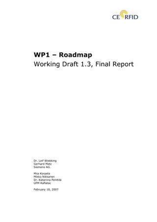
- 35. 35 ally, generally just the type of item is marked. Because of their higher data storage capacity, RFID tags allow single item identification. Figure 1 RFID applications Figure 1 tries to show how system cost, tag quantities, and security features correlate with current RFID applications. E.g. access control systems do need security (data protection, anti-cloning) but usually use low tag quantities. On item level where identification is the main task of RFID security plays a low role providing low system costs. 4.1.1 Mapping to the reference model Table 6 shows the mapping of auto-id technologies to the subcategories of the reference model (see chapter 4.2). “Y” means: “Yes”, this auto-id technology applies to the corresponding subcategory.
- 36. 36 Current use Possible useRFID application field Subcategories RFID Barcode OCR RFID Barcode OCR AA: Inhouse logistics Y Y Y Y Y Y AB: Closed loop logistics Y Y Y Y Y Y AC: Open logistics Y Y Y Y Y Y AD: Postal applications Y Y Y Y Y Y AE: Dangerous goods logistics Y Y A: Logistical track- ing & tracing AF: Manufacturing logistics Y Y Y Y Y Y BA: Archive systems Y Y Y Y Y Y BB: Asset management Y Y Y Y BC: Facility management Y Y BD: Vehicles Y Y BE: Airplanes Y Y Y Y BF: Autom./process control Y Y Y Y B: Production, monitoring and maintenance BG: Food and cons. goods Y Y Y Y Y Y CA: Fast mov. cons. goods Y Y Y Y Y Y CB: Electronic goods Y Y Y Y Y Y CC: Textile goods Y Y Y Y Y Y CD: Fresh/perishable foods Y Y CE: Pharmaceutical Y Y C: Product safety, quality and informa- tion CF: Customer info. systems Y Y Y Y DA: Access control systems Y Y DB: Animal tracking Y Y D: Access control and tracking & trac- ing of individuals DC: Personal tracking Y Y EA: Loyalty cards Y Y Y Y YE: Loyalty, mem- bership and pay- ment EB: Membership cards Y Y Y Y Y FB: Hospital management Y Y Y Y Y YF: eHealth care FC: Implants Y Y Y Y Y GB: Rental systems Y Y Y Y YG: Sports, leisure and household GD: Smart home Y Y HB: Road tolling systems Y Y Y YH: Public services HC: Banknotes Y Y Y Y Table 6 Mapping auto-id technologies to reference model OCR (optical character recognition) and barcode systems are well established auto-id systems. They provide advantages (e.g. very cheap, human readable) and disadvantages (e.g. line of sight required, soiling problems, low data ca-
- 37. 37 pacity, read-only, and no authentication). RFID can replace or supplement other auto-id technologies while offering the additional advantages of RFID: no line of sight required, reading in dirty environments, writable user data, high data capacity, high data rates, security functions, robustness, etc. There are many subcategories that function with RFID only or where RFID repre- sents a major improvement: dangerous goods logistics (e.g. temperature sensor, localisation), asset management (e.g. localisation, itinerary), facility management (e.g. security features, access control), vehicles (e.g. pressure sensors), airplanes (e.g. anti-counterfeiting), automation/process control (e.g. user data), fresh/perishable foods (e.g. temperature sensors), pharma- ceutical (anti-counterfeiting, sensors), customer information systems (e.g. usability), access control systems (e.g. authentication, anti-cloning), animal tracking (e.g. easy handling, dirty environment, anti-cloning), person tracking (e.g. authentication, anti-cloning), smart home (e.g. sensor functionality). 4.2 RFID Reference Model In order to provide a common baseline for all work packages in the CE RFID project as well as for other RFID related projects, the consortium developed a RFID Reference Model containing all application fields where RFID technology is presently used. The CE RFID Reference Model is described in separate documents (see Appendix 17.5). Table 7 shows the basic systematic of the model. The complexity of the systems is increasing from top to bottom of the table (A. to H.).
- 38. 38 Reference RFID application fields Description A. Logistical tracking & tracing Solely identification and location of goods and returnable assets (e.g. pallets or con- tainers) B. Production, monitoring and maintenance Smart systems in combination with RFID technology to support production, monitor- ing, and maintenance of goods and proc- esses Mainlyobjecttagging C. Product safety, quality and information Applications to insure quality (e.g. sensors to monitor temperature) and product safety (e.g. fight against counterfeiting) D. Access control and tracking & tracing of individuals Single function tags for identification and authorisation applications for entries and ticketing E. Loyalty, membership and payment Smart Card based identification and authorisation systems for multifunctional applications (e.g. loyalty, payment, and banking systems) F. eHealth care Systems for hospital administration and smart systems to support and monitor health status G. Sport, leisure and household Sports applications, rental systems (e.g. cars or books), smart home Taggingwithreferenceorpotentialref- erencetopeople H. Public services Systems mandated by law or to fulfil public duties (e.g. ID-cards, health insurance cards, road tolling systems) Table 7 CE RFID Reference Model main categories In the following table the subcategories covered by work package 1 are marked by “X” (column WP1).
- 39. 39 RFID application field Subcategories WP1 AA. — Inhouse logistics X AB. — Closed loop logistics X AC. — Open logistics X AD. — Postal applications X AE. – Dangerous goods logistics X A. Logistical tracking & tracing AF. — Manufacturing logistics X BA. — Archive systems X BB. — Asset management (incl. Environ- X BC. — Facility management X BD. – Vehicles X BE. – Airplanes X BF. — Automation/process control X B. Production, moni- toring and mainte- nance BG. — Food and consumer goods X CA. — Fast moving consumer goods X CB. — Electronic goods X CC. — Textile goods X CD. — Fresh/perishable foods X CE. — Pharmaceutical X Mainlyobjecttagging C. Product safety, quality and informa- tion CF. — Customer information systems X DA. — Access control systems X DB. — Animal tracking X D. Access control and tracking & trac- ing of individuals DC. — Personal tracking X EA. — Loyalty cards X EB. — Membership cards X EC. — Contactless banking cards E. Loyalty, member- ship and payment ED. — Payment and advertising via mobile FA. — Assistance for the disabled FB. — Hospital management X FC. – Implants X FD. — Medical monitoring F. eHealth care FE. — Smart implants GA. — Sports applications GB. — Rental systems X GC. — Smart games G. Sports, leisure and household GD. — Smart home X HA. — Public service maintenance HB. — Road tolling systems X HC. – Banknotes X HD. — ID cards and passports Taggingwithreferenceorpotentialreferencetoindividuals H. Public services HE. — Health insurance cards Table 8 Subcategories covered by work package 1
- 40. 40 Systems where RFID is only a small part and that are dominated by other technologies are not investigated and described in work package 1. E.g. many systems in field E, F, G, and H use additional sophisticated microcontrollers that provide complex functions (e.g. encryption, money transfer, data proc- essing). Work package 1 concentrates on the RFID applications logistics, am- bient intelligence and public security/identity management. 4.3 Application examples The following pages present some application examples with real systems available on the market or applications that can be implemented with existing RFID technologies. This chapter shows how the combination of the different RFID views lead to RFID systems that are used in many applications. 4.3.1 Logistics, supply chain management at Metro Group The most important mass market application is logistics and the supply chain (see Reference Model field A [8]). Due to cost reasons only passive RFID label tags with HF or UHF technology are used here. Some enterprises plan to use HF RFID on item level and UHF RFID on case and pallet level (e.g. pharma- ceutical industry). There is also a trend to shift item level to UHF as well. The METRO Group, the world's fourth largest retailer, will soon require that all pallets shipped to 180 locations in Germany be equipped with RFID tags using EPCglobal’s second-generation Electronic Product Code standard (Gen 2 tags [81]). The company's RFID plans were communicated to about 650 suppliers. In 2007 all Metro Cash & Carry stores as well as about 100 “real” hypermar- kets in Germany will be equipped with RFID portals in the goods entrance section. Each RFID tag carries information on it such as a serial number, model number, colour or place of assembly. The use of RFID throughout the supply chain allows the tracking of the loca- tion of a shipment and therefore renders a faster and more reliable flow of goods possible. In 2006 the METRO group introduced EPC Class 1/Gen. 2 RFID chips. In August 2006 suppliers started labelling individual shipping boxes with smart chips.
- 41. 41 4.3.2 Identity management, security, access control Access control systems (reference model fields D, E, F) need at least basic security features like secure authentication. Otherwise an intruder might eavesdrop the reader-to-tag communication and clone the tag. Authentication methods are described in chapter 9.4. In order to provide additional security RFID technology with low range capability like HF (13.56 MHz) is used. An eavesdropper has to be very close to the system and the possibility of a mix- up of tags is being reduced. An example is the TSI PRISM (http://www.tsiprism.com/) system, which tracks and records the location and movement of inmates and officers, result- ing in enhanced facility safety and security. The proprietary RFID tracking technology provides real-time inmate and officer identification. The tags can- not be cloned and must be trackable otherwise an alarm will occur. Access control is combined with real-time tracking and tracing. 4.3.3 Contactless smart card “Mifare” Mifare is the most widely installed contactless smart card technology in the world, with more than 500 million smart card ICs and 5 million reader compo- nents sold. As an example for contactless smart card technology, the different Mifare types are described in the following text. Mifare offers solutions for applications like loyalty and vending cards, road tolling, city cards, access control and gaming. (reference model fields D, E). Mifare is compliant with ISO 14443 A. It has 80% market share in the auto- matic fare collection market (source: Frost & Sullivan 2001). The product portfolio covers reader components as well as contactless and dual interface smart card ICs. Multiple sourcing exists on all levels of the value-chain (ICs, readers, cards, etc.). Tickets based on NXP Mifare Ultralight ICs can act as single trip tickets in pub- lic transportation networks, loyalty cards or even day passes at big events. They are a replacement for conventional ticketing solutions such as paper tickets, magnetic-stripe tickets or coins. Mifare Standard 1k is primarily used in closed loop systems, where value is extracted in a secure and authorized way from the card by the service pro- vider, or for fixed value tickets (e.g. weekly or monthly travel passes). An- other important application is physical access control. Here Mifare Standard 1k cards are widely used for ID cards, employee cards and company or build- ing access. Today Mifare Standard 1k ICs are in use around the globe in dif-
- 42. 42 ferent applications like public transport, road-tolling and parking meters, ac- cessing car parks and paying at fuel pumps. Mifare Mini is a further optimized version of the Mifare Standard 1k to meet the requirements of the access control and loyalty cards market. It provides significantly decreased memory size (320 Byte) making it the perfect solution for access control or loyalty applications. Mifare Standard 4k opens up new service opportunities by enabling public transport authorities to implement multi-modal systems. It allows combina- tion with contactless e-commerce and e-business applications on one single Mifare smart card. The Mifare 4k Standard IC provides increased memory size for multi-application cards. Mifare DESFire is based on open global standards for both air interface and cryptographic methods. It is compliant to all 4 levels of ISO / IEC 14443A ([78], [79]) and uses optional ISO / IEC 7816-4 commands. Contactless tick- eting and related applications such as payment at vending machines, access control or event ticketing are possible. Mifare DESFire is intended for service providers wanting to use multi-application smart cards in transport schemes, e-government or identity applications. It complies with the requirements for fast and highly secure data transmission, flexible memory organization and interoperability with existing infrastructure. Mifare PROX is a high-security, high performance dual interface IC solution at the high-end of the portfolio. Mifare PROX meets the requirements of financial applications and delivers the flexibility and security to support multiple appli- cations and service providers on a single card IC ranging from banking, e- commerce, e-government, e-business, ID card and biometric applications to electronic ticketing and other contactless services. The cards support dynamic download of Java™ applications. This means that additional applications, such as payment for public transport, access to a pub- lic library or a loyalty scheme can be added or removed even after the card has been issued. SmartMX enables the easy implementation of state-of-the-art operating sys- tems and open platform solutions including Java Card Global Platform and MULTOS. MULTOS (which stands for "Multiple Operating System") is an oper- ating system that allows multiple application programs to be installed and to reside separately and securely on a smart card with the highest levels of se- curity.
- 43. 43 The SmartMX platform is positioned to service high volume, mono- and multi- application markets such as e-government, banking/finance, mobile commu- nications, public transportation, pay-TV, conditional access, and network ac- cess. An anti-collision method (acc. ISO/IEC 14443-3) enables multiple cards to be handled simultaneously. 4.3.4 Contactless smart card “FeliCa” Sony Corp. offers a system very similar in function to the Mifare system, called FeliCa. In Nov 2006 NXP and Sony have signed a memorandum of un- derstanding to create a joint venture that will develop, manufacture and mar- ket an integrated circuit (IC) combining NXP's Mifare technology and Sony's FeliCa platform on a single chip (see http://www.rfidjournal.com/article/articleview/2842/ [9]). Contactless- payment applications using FeliCa technology are widespread in parts of Asia, while contactless payment applications using the Mifare platform are common in Europe. (reference model fields D, E) In Hong Kong the Octopus Card was initially a payment system for public transport (bus, metro, ferry boat and light rail). The services have expanded to pay for purchases at a convenience stores, fast food stores, and vending machines. The card also serves as employee ID, student ID and other ID cards, and has grown into a major choice for office entry/exit control, parking area entry/exit control. The "ez-link Card" an automatic public transport payment system for bus, metro and railroad was introduced in April 2002 in Singapore using the FeliCa technology. About 8 million cards are already issued in Singapore, daily proc- essing adding up to roughly 4 million transactions per day. The metro system of Shenzhen (China) uses FeliCa technology for passenger tickets. The passenger tickets are available in various forms and types de- pending on their purpose of use. These include regular commuter passes called the Trans Card, as well as student discount tickets and tokens as pay- ment for a one-way metro ride. The metro in Delhi, the capital of India, started application of FeliCa technol- ogy in December 2002 for the passenger ticketing system. The Travel Card, a card-shaped ticket, is reusable by charging values to the card.
- 44. 44 The first metro system in Thailand started operations in Bangkok in July 2004 and employs FeliCa technology. “Suica”, implementing FeliCa technology, was comprehensively introduced in the Tokyo metropolitan area and the peripheral access by East Japan Railway Company. After touching the reader with “Suica”, the automatic ticket gate reads and charges the IC card. This way, the passage through the wicket is very con- venient for the passengers. Since it was first introduced, Suica has rapidly spread in use with 10 million cards in circulation in about 3 years, with the statistics rapidly over 14 million today (source: Sony Corp.). The "Tokyo-Mitsubishi VISA“-Super IC Card is a multi-functional IC card. The dual interface IC card system employed by the bank uses Sony's contactless FeliCa IC card technology. Iyo Railway Group kicked off the "IC e-Card" services, applying FeliCa tech- nology, for their public transport system in Matsuyama City, Ehime. 4.3.5 µ-chip The µ-chip (Hitachi Ltd.) is a passive IC (tag chip) containing 128-bit read only memory to store a unique ID. The ID is written by the manufacturer and cannot be altered afterwards. It has no anti-collision control. In other words a reader cannot read more than one chip at a time. Chip size is 0.4 mm x 0.4mm. The passive chip does not contain a battery. A corresponding reader generates a microwave signal at 2.45 GHz. The tag chip converts the micro- wave into electric power and transmits its µ-chip ID back to the reader. The maximum reading range is about 25 cm. The chip needs an external antenna to form a complete tag. The antenna offered by Hitachi has the size of 56 mm x 4.75 mm, which is smaller than the typical coil antenna used for 13.56 MHz smart cards. A typical reader has 300 mW output power and a 4 patch an- tenna with circular polarisation. The response time of the chip is 20 msec. The µ-chip was used at the Expo 2005 in Nagoya, Aichi in Japan for admission tickets. (reference model fields A. Logistical tracking & tracing, D. Access con- trol and tracking & tracing of individuals, H. Public services). The µ-chip has been developed by Hitachi Ltd. for banknote identification (reference model subcategory Banknotes).
- 45. 45 4.3.6 Animal identification Destron® Technologies offers tamperproof full duplex (FDX-B) electronic transponders for the cattle industry. These tags are suited for harsh environ- ments. They carry a 15 digit numeric ID, by which the animal can be identi- fied (reference model field D. Access control and tracking & tracing of indi- viduals). There are products for animal identification (compliant with ISO 11784 and ISO 11785 defining data structure and air interface), e.g. ear tags that can be also read visually or glass embedded tags (about 23 mm x 4 mm), which is implanted. A bolus (about 65 mm x 21 mm) may be placed in the rumen of an animal. Another possibility would be to put a collar containing an RFID tag on the animal. This is primarily used on pets, like cats or dogs, but may also be used on cows. These tags are passive and work at 134.2 kHz. Security functions are not always needed unless access control is required. In order to identify an animal or object unambiguously low range systems like HF RFID (13.56 MHz) and LF RFID (134.2 kHz) suit well. 4.3.7 Automation, production management, manufac- turing A big industrial application field is the area of automation, production and manufacturing (reference model field B). In most cases so-called “closed loop” systems without security functions are used. Tag and reader usually stay in- side the same production hall. Proprietary systems with special system pa- rameters (e.g. high robustness, high reliability) that do not need to follow standards like ISO/IEC 18000 ([78], [79]) or EPCglobal ([81]) can be used here. The choice of frequency bands and system properties (memory capac- ity, temperature range, robustness, etc.) directly follows system requirements of the application. At the Munich plant of BMW, Moby identification systems (RFID Systems SI- MATIC RF by Siemens AG) are used for transmission and storage of quality and safety relevant data. Integrated data management is done by suitable tags. E.g. Moby E is used in the front and rear axle assembly. The different work piece carriers are marked with tags to bring them to the correct workstations. RFID is likewise used in the cable harness assembly, the power train elements assembly, car body and final assembly and for locating vehicles on the factory premises. The data stored on the tags during production ensure that vehicle-specific parts are being assembled correctly and the relevant quality data are recorded.
- 46. 46 4.3.8 Automotive In the automotive sector there are various RFID applications (reference model fields D. Access control and tracking & tracing of individuals, E. Loyalty, membership and payment, H. Public services). Data security, data protection and privacy are most important system properties. Card type tags with built- in security functions (authentication, secure data access, encryption) are needed to fight tag-cloning, data tampering and deception. Dependant on the reading range the application requires HF or UHF systems with security func- tions that are suited for these applications. A high security intelligent license tag system may be used to detect and pre- vent vehicle misuse. Parked cars can be checked without owner/driver atten- dance. The vehicle data can instantly be verified by authorities. The tag may contain public data (e.g. license number) and/or protected data (owner, taxes, etc.).These data could be used to enforce payments for registration, tax and/or insurance. Protected storage levels can be licensed to private com- panies e.g. for access control. 4.3.9 Smart drug cabinet A smart drug cabinet is a future scenario providing automatic information about access and inventory (reference model fields C. Product safety, quality and information, F. eHealth care). Security functions are required (authentica- tion, secure data access, encryption) to fight tag-cloning, data tampering, deception. The RFID reader at the drug cabinet reads the tag of the accessing person and decides if access is granted. The same reader may register drugs that are taken out from the cabinet or placed into it. This information can also be used to monitor the supply chain. If a patient tag is read, drug assignment and therapy control are possible (see also next example). 4.3.10 Medical, pharmaceutical, health care In eHealth care applications (reference model field F) special high security functions are required since patient data may be stored on the tag and trans- ferred to/from the tag (authentication, secure data access, secure data stor- age, encryption). Such high security functions are currently available on HF RFID (13.56 MHz) only. Wrist bands with RFID tags can be used to identify the patient, confirm the medicine and dose administered and even the time this has to be done. In contrast to barcode systems, RFID tags can be read through and around the human body. The data on the tag can be changed if
- 47. 47 needed, to always keep patient data up-to-date. The U.S. navy tracks wounded in Iraq, using RFID technology. 4.3.11 VeriChip The U.S. based vendor VeriChip Corp. provides state-of-the-art security solu- tions that identify, locate, and protect people, their assets, and their environ- ments. It offers infant protection, wander prevention, asset tracking, and pa- tient identification applications, especially for the healthcare industry (refer- ence model field F). Within their systems, VeriChip offers three main categories of tags for these purposes. The first is a passive, human-implantable RFID microchip, measur- ing the size of a grain of rice. It is inserted just under the skin of the patient's upper right arm. This chip is approved by FDA (US- Food and Drug Admini- stration). The chip can be read through a fixed or handheld reader. The read- ing distance typically is a few centimetres. The unique 16-digit identifier, which is the only information stored on the chip, can be connected to an on- line patient information data base. The patient record can contain vital infor- mation related to the patient, e.g. lab test data and pharmacy records. The implanted chip cannot easily be lost or stolen. Due to the missing security functions the tag can be cloned. Patient data cannot be eavesdropped without access to the corresponding database system. Today, according to VeriChip Corp., VeriChip systems are installed in over 4,000 locations worldwide in healthcare, security, industrial, and government markets. Currently, 110 medical facilities have committed to adopt the VeriMed Patient Identification System in their emergency rooms while over 2,500 people have gotten a VeriChip microchip worldwide. Another kind of tag VeriChip offers are active RFID tags worn by individuals (usually on the wrist or leg). These tags are used to help prevent infant ab- ductions and accidental mother/baby switching and prevent residents from wandering out of designated areas. VeriChip also offers a selection of active and passive RFID tags which can be affixed to items. Items to be tagged include equipment, parts and consum- ables, facilitating inventory management. 4.4 Niche applications RFID can also be used for some non-mass or niche applications.
- 48. 48 4.4.1 Tree identification Tags can provide serial numbers for trees. The College of Forest Resources at the University of Washington uses a system where tags are placed inside trees. The tags can be read with a hand-held reader outside the tree. Security functions are not needed here. Due to the small tag cases HF is mainly used here with small coils as antennae. The system is used by the University of Washington for a self-guided tree tour, where the participants carry a PDA with an integrated reader. 4.4.2 Identification of bees RFID tags attached to bees make it possible to track the activities of single insects. The bio centre at the University of Würzburg, Germany uses very small tags for identifying bees. The whole tag must fit on the head of a bee. The chip weighs 2.4 mg. Due to the small tag antenna the reading range is rather low. The reader antenna has to be placed near the entrance of the beehive. 4.4.3 Railroad car identification Figure 2 shows an application where railroad cars are to be identified. Major requirements are: passive tag, high speed reading, high reading range, high robustness and high temperature range. Classical RFID systems do not pro- vide all these properties in combination. Here an RFID system on 2.45 GHz based on surface acoustic waves (SAW) is used (RFID system by Siemens AG). In the centre the tag’s RF response signal is shown.
- 49. 49 Figure 2 Passive and robust RFID systems for identification of railroad cars 4.5 Mapping to the reference model Table 9 shows the mapping of application examples to the subcategories of the reference model (see chapter 4.2). “Y” means: “Yes”, this application ex- ample applies to the corresponding subcategory.
- 50. 50 Current useRFID- application field Subcategories Logistics,supplychainman- agementatMetroGroup Identitymanagement,security, accesscontrol ContactlesssmartcardMifare ContactlesssmartcardFeliCa µ-chip Animalidentification Automation,productionman- agement,manufacturing Automotive Smartdrugcabinet Medical,pharmaceutical,health care VeriChip Treeidentification Identificationofbees Railroadcaridentification AA: Inhouse logistics Y AB: Closed loop logistics Y AC: Open logistics Y AD: Postal applications AE: Dangerous goods logistics A: Logistical tracking & trac- ing AF: Manufacturing logistics Y Y BA: Archive systems BB: Asset management Y BC: Facility management Y Y Y BD: Vehicles Y Y BE: Airplanes BF: Autom./process control Y B: Production, monitoring and maintenance BG: Food and cons. Goods Y Y CA: Fast mov. cons. Goods Y CB: Electronic goods Y CC: Textile goods Y CD: Fresh/perishable foods Y CE: Pharmaceutical Y Y Y C: Product safety, quality and information CF: Customer info. systems Y DA: Access control systems Y Y Y Y Y DB: Animal tracking Y Y D: Access con- trol and track. & tracing of individuals DC: Personal tracking Y Y Y Y Y EA: Loyalty cardsE: Loyalty, memb. and payment EB: Membership cards Y Y Y FB: Hospital management Y Y Y Y Y YF: eHealth care FC: Implants Y GB: Rental systemsG: Sports, lei- sure and household GD: Smart home HB: Road tolling systems YH: Public ser- vices HC: Banknotes Y Table 9 Mapping application examples to reference model
- 51. 51 5 Transponder Classes View Another view on RFID systems derives from the approach to classify RFID systems by the capabilities of their tags. A meanwhile widely used classifica- tion system has been established by the MIT Auto-ID Center and is now con- tinued by EPCglobal Inc [81]. 5.1 EPCglobal classes EPCglobal is a subscriber-driven organisation comprised of industry leaders and organisations, focused on creating global standards for the EPCglobal Network [81]. EPCglobal was formed as the successor organization to the MIT Auto-ID Center, which started the EPC technology. The Electronic Product Code (EPC) should provide unique ID numbers for objects and support the use of radio frequency identification (RFID) in trading networks. The goal is in- creased efficiency throughout the supply chain and higher information flow between companies and their trading partners. EPC tag class Tag type Tag class capabilities Class 0 Read only, (i.e., EPC number (64 bits) hard coded by manufacturer) Class 1 Read, write once (i.e., EPC number (96…256 bits) can be encoded onto the tag later in the field) Class 2 passive Read / write (larger memory, user data) Class 3 semi- passive Class 2 capabilities plus a power source to provide in- creased range and/or advanced functionality (e.g. sen- sors) Class 4 Class 3 capabilities plus active communication and inter- tag communication Class 5 active Class 4 capabilities plus communication with passive tags as well Table 10 EPCglobal RFID technology classes Table 10: EPCglobal RFID technology classes shows a system introduced by the RFID user organisation EPCglobal [81]. It is one possible view of tag classes, which classifies tags according to their data handling capabilities, en- ergy source and communication skills. EPCglobal class 0 up to class 2 build the group of passive tags. Class-3-tags are semi-passive and class 4 and 5 form the active tag group. From class 0 up to class 5 the RFID system performance and capabilities increase. Current
- 52. 52 systems on the market do not cover all classes. Only class 0 and class 1 are accompanied by corresponding international standards (here EPCglobal stan- dards [81]). Although, in principle, this classification system is not limited to tags defined by EPCglobal standards [81], it is used mainly by the EPCglobal community. In March 2007, the most advanced passive tag technology is the so-called “Class 1 Generation 2” (short “Gen2”) technology, according to the EPCglobal UHF standard [81]. The air interface is also compatible with the new ISO/IEC 18000-6c (2006) ([78], [79]). 5.1.1 Passive tags Passive tags have no energy source. They take their power supply out of the reader’s magnetic or electromagnetic field. Because they need no batteries, they can be built very cheap and very small in size. Class 0 Class 0 are the simplest passive tags, according to the EPCglobal system [81]. They are read-only tags with a simple ID number. The ID number is built-in when the tag (chip) is manufactured and can not be altered. The ID is typi- cally a 64 or 96 bit number, which can be the EPC (Electronic Product Code). For EAS (Electronic Article Surveillance) systems, the tag may contain only one bit of information, carrying just the information that “something” is in reading range of the reader. The companies Symbol and Impinj manufacture a programmable tag, which they call Class 0+. It is not broadly available. "Class 0+" is not an official standard, and Symbol and Impinj tags are not interchangeable. Class 1 Class 1 are read/write passive tags that can only be written once. They can store a larger ID number and some additional data. The ID and data can be written by the manufacturer or the customer. Once written, they can not be altered. Many companies offer tags that comply with the EPCglobal UHF Gen2 specification [81]. E.g. Impinj Inc. (USA) offers tags named Monaco™ and Monza™ for item level tagging which are certified by EPCglobal [81]. Class 2 Class 2 are read/write passive tags that can be written many times. They can store a larger amount of additional data and may have additional functionality like data logging and/or cryptography.
- 53. 53 5.1.2 Semi-passive tags Semi-passive tags use an auxiliary energy source (usually a battery). They use the energy out of the source for supplying the tag and producing the re- sponse modulation. The response signal itself is generated passively as with passive tags. Class 3 Class 3 tags use their power source (battery) to provide additional functional- ity like sensor(s) and/or increased reading range. A typical example is a semi- passive tag offered by the Italian company CAEN S.p.A. (http://www.caen.it/rfid/index.php). This tag samples the temperature in 6- second-intervals and transfers its data to the reader when interrogated. The lithium battery has a life time of 3 years. Its typical application fields are the transportation and the supply chain of medical products, foods etc., since it allows continuous monitoring of the goods’ condition. 5.1.3 Active tags Active tags use an auxiliary energy source (usually a battery). The energy from the source is used for all functions of the tag. The tag is generating an RF signal by itself without the support of the reader. The energy source may also be used for the supply of additional components like sensors, actuators, crypto engines, data processing units, etc. Class 4 Class 4 provides the same functionality as class 3 and in addition to that the tags generate their own RF signal and can communicate with other active tags. Active tags may send their data independently from interrogation sig- nals of a reader (beacon tag). E.g. the US-based company Savi Technology (http://www.savi.com) offers sensor tags that consist of a high performance active RFID tag for real-time container tracking during transit, including sen- sors that detect any unauthorized opening of the container. The sensor moni- tors the environmental conditions inside the container. Any change in tem- perature, humidity and shock is detected. Class 5 Class 5 provides the same functionality as class 4 and in addition to that the tags can communicate with other active, semi-passive and passive tags. Class 5 tags essentially have reader capabilities. An application field for these tags may be sensor networks and ambient intelligence systems.
- 54. 54 5.1.4 Mapping to the reference model Table 11 shows the mapping of basic transponder classes to the subcategories of the reference model (see chapter 4.2). “Y” means: “Yes”, this transponder class can be used in the corresponding subcategory.
- 55. 55 Current use Possible useRFID- application field Subcategories Passivetags Semi-passivetags Activetags Passivetags Semi-passivetags Activetags AA: Inhouse logistics Y Y AB: Closed loop logistics Y Y AC: Open logistics Y Y AD: Postal applications Y Y AE: Dangerous goods logistics Y Y Y Y Y Y A: Logistical tracking & trac- ing AF: Manufacturing logistics Y Y BA: Archive systems Y Y BB: Asset management Y Y BC: Facility management Y Y BD: Vehicles Y Y Y Y Y Y BE: Airplanes Y Y Y Y BF: Autom./process control Y Y Y Y Y Y B: Production, monitoring and maintenance BG: Food and cons. goods Y Y CA: Fast mov. cons. goods Y Y CB: Electronic goods Y Y CC: Textile goods Y Y CD: Fresh/perishable foods Y Y Y Y CE: Pharmaceutical Y Y Y Y Y Y C: Product safety, quality and information CF: Customer info. systems Y Y DA: Access control systems Y Y DB: Animal tracking Y Y D: Access con- trol and track. & tracing of indi- viduals DC: Personal tracking Y Y EA: Loyalty cards Y YE: Loyalty, memb. and payment EB: Membership cards Y Y FB: Hospital management Y YF: eHealth care FC: Implants Y Y Y Y Y Y GB: Rental systems Y YG: Sports, lei- sure and household GD: Smart home Y Y Y Y Y Y HB: Road tolling systems Y Y Y YH: Public ser- vices HC: Banknotes Y Y Table 11 Mapping basic transponder classes to reference model
- 56. 56 5.1.4.1 Passive tags Passive tags get all their operational power from the reader’s field. They are used in all subcategories, except fresh/perishable foods (due to the tempera- ture sensors) and road tolling systems (high reading ranges (>7 metres)). In the future, passive temperature sensor tags might be developed that can be used here. But existing technology uses active RFID with sensors. High read- ing range and high reliability in road tolling systems are achieved with semi- passive or active tags. 5.1.4.2 Semi-passive and active tags Semi-passive and active tags use an additional energy source (e.g. battery) to power their circuitry. Semi-passive tags use the same air interface as pas- sive tags while active tags actively generate a radio frequency signal. Semi- passive tags reach higher reading ranges than passive tags, since the main circuitry is powered from the energy source rather than from the RF field. Ac- tive tags reach the highest reading ranges since they generate their own RF signal out of the energy source (e.g. battery). Due to the additional energy source, both tag classes are rather expensive in comparison to passive tags. Cost effective usage is therefore limited to subcategories that need additional functionality (e.g. sensors, data processing, networking) or very high reading ranges and reliability, as in dangerous goods logistics (e.g. temperature sen- sors), vehicles (sensors), automation/process control (e.g. sensors), fresh/perishable foods (temperature sensors), pharmaceuticals (temperature sensors), implants (temperature sensors), smart home (sensors) and road tolling systems (high reading range, high reliability).