
Recommended
Recommended
More Related Content
What's hot
What's hot (20)
Similar to Soil exploration by abhishek sharma
Similar to Soil exploration by abhishek sharma (20)
Recently uploaded
Recently uploaded (20)
Soil exploration by abhishek sharma
- 2. A detailed investigation for site is essential before a design can be finalized. The object of subsurface and related site investigation is to provide the engineer or architect with as much information as possible about the existing conditions, for example, the exposed overburden, the course of a stream nearby, a rock outcrop or a hillock, vegetation, and other geological features of the area. It is equally important to know the subsoil conditions below a proposed structure. The field and laboratory investigations required to obtain the necessary data of the soils for proper design and constructions of any structure at the site are collectively called Soil Exploration. Abhishek sharma 661/15
- 3. Abhishek sharma 661/15 Investigation of the underground conditions at a site for the economical design of the substructure elements. Purpose of Exploration To determine the general suitability of the site. To find the nature of each stratum and engineering properties of the soil and rock, which may affect the design and mode of construction of proposed structureand foundation. To find out the sources of construction material. To ensure the safety of surrounding existing structures To locate the ground water level and possible corrosive effect of soil and water on foundation material. To predict the settlements Selection of suitable construction technique. Selection of type and depth of foundation. ❖ ❖ ❖ ❖ ❖ ❖ ❖ ❖
- 4. A SAMPLE There are 2 types of samples : 1. Disturbed Sample 2. Undisturbed Sample In first one, structure of the soil get disturbed And actual results can not be determined. But in latter case we can get the actual result because the soil sample is not disturbed and hence the structure of the soil remains same. In INDIA Soil Exploration Should be done as per IS 1892.1979. Abhishek sharma 661/15
- 5. Foundations of Multi-storeyed Buildings (IS: 1892,1979) Earth and rockfill Dams (IS: 6955, 1973) Power House Sites (IS: 10060, 1981) Canals and Cross Drainage Works (IS: 11385, 1985) Portsand Harbours (IS: 4651 – Part 1, 1974) Abhishek sharma 661/15
- 6. Exploration program involves location and depth of borings, test pits or other methods to be used, and methods of sampling and tests to be carried out to determine the stratification and engineering properties of the soils underlying the site. The principal properties of interest Will the shear strength, deformation and hydraulic characteristics of soil The program should be planned so that the maximum amount of information can be obtained at minimum cost. The actual planning of a subsurface exploration program includes the following steps: Gather all available information Reconnaissance Preliminary exploration Detailed exploration Abhishek sharma 661/15
- 7. Abhishek sharma 661/15 Assemble all information on dimensions, column spacing, type and use of structure, basement requirements and any special architectural consideration of the proposed building For bridges the soil engineer should have access to type and span lengths as well as pier loadings. This information will indicate any settlement limitations, and can be used to estimate foundation loads.
- 8. Abhishek sharma 661/15 Site reconnaissance would help in deciding future programme of field investigations ? that is, to assess the need for preliminary or detailed investigations. This would also help in determining scope of work, methods of exploration to be adopted, field tests to be carried out and administrative arrangements required for the investigation. The main Objective of site reconnaissance is enquiries regarding earlier use of site. • Site reconnaissance includes a study of local topography, excavations, ravines, quarries, escarpments; evidence of erosion or landslides. • It Includes study of behaviour of existing structures at or near the site; water level in streams, water courses and wells; flood marks. • It includes study of Information on some of these may be obtained from topographical maps, geological maps, pedological and soil survey maps, and aerial photographs. (as per clause 2.2.1)
- 9. In this step a few borings are made to establish in a general manner. To know the stratification, types of soil to be expected, andpossibly the location of thegroundwater table. If the initial borings indicate the upper soil is loose or highly compressible, One or more borings should be taken to rock, or hard strata, A feasibility exploration program should include collection of enough site data and sample recovery to approximately determine the properties of soil, foundation design and identify theconstruction procedures. To find the thickness and composition of each soil layer. Abhishek sharma 661/15
- 10. Here we make a detailed planning for soil exploration in The form trial pits or borings, their spacing and depth. Accordingly, the soil exploration is carried out. The details of the soils encountered, the type of field tests adopted and the type of sampling done, presence of water table if met with are recorded in the form of bore log. The soil samples are properly labeled and sent to laboratory for evaluation of their physical and engineering properties. The report is prepared with clear description of the soils at the site, methods of exploration, soil profile, test methodsand results, and the location of the groundwater. This should include information and/or explanations of any unusual soil,water bearing stratum, and soil and groundwater condition that may be troublesome during construction.
- 11. The depth of exploration required depends on the type of proposed structure, its total weight, the size, shape and disposition of the loaded areas, soil profile, and the physical properties of the soil that constitutes each individual stratum. Normally, it should be one and a half times the width of the footing below foundation level. In certain cases, it may be necessary to take at least one bore hole or cone test or both to twice the width of the foundation. If a number of loaded areas are in close proximity the effect of each is additive. In such cases, the whole of the area may be considered as loaded and exploration should be carried out up to one and a half times the lower dimension. In weak soils, the exploration should be continued to a depth at which the loads can be carried by the stratum in question without undesirable settlement and shear failure. (As per clause 2.3.2) Abhishek sharma 661/15
- 12. NUMBER AND DISPOSITION OF TRIAL PITS AND BORINGS : The disposition and spacing of the trial pits and borings should be such as to reveal any major changes in thickness, depth or properties of the strata over the base area of the structure and its immediate surroundings. For a compact building site covering an area of about 0.4 hectare, one bore hole or trial pit in each corner and one in the centre should be adequate. For very large areas covering industrial and residential colonies, the geological nature of the terrain will help in deciding the number of bore holes or trial pits. (as per clause 2.3.1) Abhishek sharma 661/15
- 13. Abhishek sharma 661/15 Depth up to which stress intensity is 0.2 times the stress near application of load is said to be significant depth of exploration.
- 14. Abhishek sharma 661/15 Sl.No. TypeOfFoundation DepthOfExploration 1 Isolated spread footing Or Raft 1.5B 2 Adjacent footings with Clear spacing less than 2B 1.5L 3 Pile foundation 10to30mOR1.5B 4 Base of retaining wall 1.5B(Basewidth) 1.5H(Exposed height of wall face) [whichever is Greater] 5 Floating basement Depth of construction 6 Dams 1. 1.5 times of bottom width of earth dams 2. 2 times of height from stream bed to crest for concrete dams, for dams less than 30m high 3. Up to bed rock, in all soft, unstable and Permeable strata.
- 15. Sl.No. TypeOfFoundation DepthOfExploration 7 RoadsCuts 1. 1m little cut or fill is required 2.In cut sections, 1. below Formation level 3. In deep cuts, equal to the bottom Width or depth of the cut 8 RoadFill 2m Below ground Level or equal to the height Of the fill which ever is Greater B = Width of the foundation L = Length of the foundation Abhishek sharma 661/15
- 16. ❖ Split spoon Sampler ❖ Scraper Bucket Sampler ❖ Shelby tube or Thin Walled Sampler ❖ Piston Sampler Abhishek sharma 661/15
- 17. Abhishek sharma 661/15 It has an inside diameter of 35mm and an outside diameter of 50mm. Has a split tube which is held together using a screw- on driving shoe at the bottom end and a cap at the upperend. 4 vent posts are provided to improve recovery of sample. The thicker wall of the standard sampler permits higher driving stresses than the Shelby tube but with higher levelsof soil disturbances. It is used in SPT test. Splitspoon samplesare highlydisturbed. They are used for visual examination and for classification tests.
- 19. Scraper bucket can be used in case of Sandy soil containing pebbles (gravels) also below water table, it is difficult to use splitspoon sampler. Driving point is attached at the end. It hasvertical slit in the upperportionof the sampler. As the sampler rotates the cutting of disturbed sample is collected in slit. Abhishek sharma 661/15
- 20. Abhishek sharma 661/15 It is a thin-walled seamless steel tube of inside diameter 50 to 76.2mm, outer diameter upto 125mm and length of 600-900mm. The bottom end of the tube is sharpened. The tubes can be attached to drilling rods. The drilling rod with the sampler attached is lowered to the bottom of the borehole and the sampler is pushed into the soil, when the required depth is reached it is twisted to 360 degree twice. For sandy soil length of tube = 5xdia to 10xdia For Clayey soil length of tube = 10xdia to 15xdia The sheared soil sample inside the tube at the bottom is then pulled out and the two ends of the sampler are sealed and sent to the lab. The samples can be used for consolidation and shear tests as it is undisturbed.
- 22. When sampling very soft and sensitive clays to get high quality undisturbed samples, they tend to fall out of the sampler. Then piston samplers are used. They consist of a thin wall tube with a piston. Initially, the piston closes the end of the thin wall tube. The sampler is lowered to the bottom of the borehole and then the thin wall tube is pushed into the soil hydraulically past the piston. Later the pressure is released through a hole in the piston rod. To a large extent, the presence of the piston prevents distortion in the sample by not letting the soil squeeze into the sampling tube very fast and by not admitting excess soil. Consequently, samples obtained in this manner are less disturbed than those obtained by Shelby tubes. Abhishek sharma 661/15
- 24. It may be necessary to core rock if bedrock Is encountered at a certain depth during drilling. It is always desirable that coring be done for at least 3 m. If the bedrock is weathered or irregular, the coring may need to beextended toa greaterdepth. For coring, a coring bit is attached to the core barrel and core barrel is attached to the drilling rod. The cutting element in the bit may be diamond, tungsten, or carbide. The coring is done by rotary drilling. Water is circulated and cuttings are washed out Abhishek sharma 661/15
- 25. Rock cores obtained by such barrels can be fractured because of torsion. To avoid this problem, one can use double-tubecore barrels. On the basis of the length of the rock coreobtained the following quantities can be obtained for evaluation of the qualityof rock Abhishek sharma 661/15
- 26. RQD was developed in 1964 by D. U. Deere*. It is determined by measuring the core recovery percentage of core chunks that are greater than 100 mm in length. Core that is not hard or sound should not be counted even if they are 100 mm in length. RQD was introduced for use with core diameters of 54.7 mm. It is a leading indicator for low-quality rock zones. Today RQD is used as a standard parameter in drill core logging and forms a basic element value of the major mass classification systems. Abhishek sharma 661/15
- 28. In areas which have already been developed, advantage should be taken of existing local knowledge, records of trial pits, bore holes, etc, in the vicinity, and the behaviour of existing structures, particularly those of a nature similar to that of the proposed structure. In such cases, exploration may be limited to checking that the expected soil conditions are those as in the neighborhood. Abhishek sharma 661/15
- 29. Trial pits are applicable to all types of soils, which Provides visual inspection of soil in their natural condition in either disturbed or undisturbed state. Here depth of investigation is limited to 3 to 3.5m.There are 2 ways 1. Pits and trenches 2. Drifts and Shafts Abhishek sharma 661/15
- 30. Abhishek sharma 661/15 1. Pits and Trenches Pits: They are excavated at site for inspection of strata so as t0 provide necessary working space. According to IS 4453 1967, a clear working space at the bottom of the pit should be 1.2 m x 1.2 m. Shallow pits (upto 3m) do not require lateral support. For depth greater than 3m and GWT arises then lateral support in the form of sheeting and bracing is required.
- 31. Trenches: Theycan bedefined as long shallow pits. It is continuous overa considerable length and provides exposure along a line. On slopes trenches are more suitable than pits. Abhishek sharma 661/15
- 32. Drifts: They are the horizontal tunnels made in the hill sides to determine the nature and structure of the geological strata. According to IS 4453-1980 a drift should be 1.5m wide and 2m height in hard rock. In soft rock arched roof can Be provided. Shafts: Large sized vertical holes made in the geological formation are called as shafts For Circular Diameter = 2.4m (min) For Rectangular Width = 2.4m Usuallydone fordepth greater than 4m. Abhishek sharma 661/15
- 34. This method consist of excavating trial pits at the site and thereby exposing the subsoil surface thoroughly, enabling undisturbed samples to be taken. The undisturbed sample can be obtained by sharp-edged thin wall tubes into the ground by generally hammering or pressure. Hand cut samples known as chunk samples. This method is generally used for depth upto 3m Deep trial pits are used to investigate open fissures. If a soil is easily disturbed a firmly constructed wooden box, with a lid and bottom removed, is kept around the protuding sample block so as to leave a space of about 25 mm between the sample and sides of the box. The space between the sample and side of the box is filled with moist saw dust or similar packing material. Abhishek sharma 661/15
- 36. Auger boring - An auger may be used for boring holes to a depth of about 6 m in soft soil which can stand unsupported but it may also be used with lining tubes if required. Mechanically operated augers are suitable for gravelly soils or where a large number of holes are to be made. Shell and Auger Boring A hand rig may be used for vertical boring up to 200 mm in dia. and 25m in depth. In alluvial deposit depth of the bore hole may be extended up to 50 m with a mechanized rig. Augers for soft to stiff clay. Shell for very stiff and hard clay. Abhishek sharma 661/15
- 37. Hand operated Helical Auger Mechanical Operated Helical Auger Hand operated post hole auger Abhishek sharma 661/15
- 38. This method consists of breaking up of the formation by repeated blows from a bit or a chisel. Water should be added to the hole at the time of boring, and the debris baled out at intervals. The bit may be suspended by a cable or rods from a walking beam or spudding device. Where the boring is in soil or into soft rocks and provided that a sampler can be driven into them, cores may be obtained at intervals using suitable tools; but in soils, the material tends to become disturbed by the action of this method of boring and for this reason, the sample may not be as reliable as by the shell and auger method. As these machines are devised for rapid drilling by pulverizing the material, they are not suitable for careful investigation. However, this is the only method suitable for drilling bore holes in boulderous and gravelly strata. Abhishek sharma 661/15
- 40. In this method, water is forced under pressure through an inner tube which may be rotated or moved up and down inside a casing pipe. The lower end of the tube, fixed with sharp edge or a tool, cuts the soil which will be floated up through the casing pipe around the tube. The slurry flowing out gives an indication of the soil type. In this method heavier particles of different soil layers remain under suspension in the casing pipe and get mixed up, and hence this method is not suitable for obtaining samples for classification. Whenever a change in strata is indicated by the slurry flowing out, washing should be stopped and a tube sampler should be attached to the end of the drill rod or the inner tube. Samples of the soil should be obtained by driving the sampler into the soil by hammering or jacking. Jacking or pulley method should be used when undisturbed samples are required. Initially fish-tail bit or pistol bits are used for drilling bore hole up to weathered material. These bits should be replaced by tungsten carbide or diamond bits. Double tubecore barrels are recommended for drilling in weathered rock stratum, with seaming shells and core catcher as required. Abhishek sharma 661/15
- 43. Sl.No. Typeofproject Spacing(m) 1 Multi-storeybuilding 10-30 2 IndustrialPlant 20-60 3 Highway 250-500 4 ResidentialSubdivision 250-500 5 DamsandDikes 40-80 Abhishek sharma 661/15
- 44. In this system, boring is effected by the cutting action of a rotating bit which should be kept in firm contact with the bottom of the hole. The bit is carried at the end of hollow, jointed drill rods which are rotated by a suitable chuck. A mud-laden fluid or grout is pumped continuously down the hollow drill rods and the fluid returns to the surface in the annular space between the rods and the side of the hole, and so the protective casing may not be generally necessary. In this method cores may be obtained by the use of coring tools. In case gravel and kankar are encountered, a gravel trap fitted with Stays around the drill rod, a little above the cutter, may be used. The trap consists of 80 to 100 cm long hollow cylinder having a conical shape at bottom. Holes of 3 mm diameter are also drilled in the drill rod within the trap as well as in the conical portion of the trap. During boring, gravel and kankar rise a little and then settle into the trap. With the provision of holes, no finer materials settle in the trap. Abhishek sharma 661/15
- 46. Abhishek sharma 661/15 Core drilling-core drills shall be so designed that in sound ‘rock, continuous recovery of core is achieved. Water is circulated down the hollow rods, which returns outside them, carrying the rock cuttings to the surface as sludge. These shall be retained as samples in traversing friable rock where cores cannot be recovered. It is important to ensure that boulders, or layers of cemented soils are not mistaken for bed rock. This necessitates core drilling to a depth of at least 3 m in bed rock in areas where boulders are known to occur. For shear strength determination, a core with diameter to height ratio of 1 : 1 is required. Rock pieces may be used for determination of specific gravity and classification.
- 47. A pressure meter (see Fig. 5 ) applies a uniform radial stress to the bore hole at any desired depth and measures consequent deformation. The test involves lowering of an inflatable cylindrical probe to the test depth in a bore hole. The probe is inflated by applying water pressure from a reservoir. Under pressure it presses against the unlined wall of the bore hole and causes volumetric deformation. The stress on the bore-hole wall is the pressure of water applied. The deformation of the bore hole is read in terms of volume corresponding to fall in water level of the reservoir. The readings are plotted as shown in Fig. 6. Abhishek sharma 661/15
- 50. Geo-physical methods are used when the depth Of exploration is very large, and also when the speed of investigation is of primary importance. The major method of geo-physical investigations are: gravitational methods, magnetic methods, seismic Refraction method, and electrical resistivity method. Out of these, seismic refraction method and electrical resistivity methods are the most commonly used for Civil Engineering purposes. It is a non- intrusive method of “seeing” into the ground. Geophysical methods includes surface and down- hole measurement techniques which provide details about subsurface hydro-geologic and geologic conditions. These methods have also been applied to detecting contaminant plumes and locating buried waste materials. some methods are quite site specific in their performance. Abhishek sharma 661/15
- 52. In this method, shock waves are created into the soil at their ground level or a certain depth below it by exploding small charge in the soil or by striking a plate on the soil with a hammer. The radiating shock waves are picked up by the vibration detector (also called geophone or seismometer) where the time of travel of the shock waves gets recorded. A number of geophones are arranged on surface , The shock waves travels directly from the shock point along the ground surface and are picked first by the geophone. The other waves which travel through the soil get refracted at the interface of two soil strata. The refracted rays are also picked up by the geophone. If the underlying layer is denser, the refracted waves travel much faster. As the distance between the shock point and the geophone increases, the refracted waves are able to reach the geophone earlier than the direct waves. By knowing the time of travel primary and refracted waves at various geophones, the depth of various strata can be evaluated, by preparing distance-time graphs and using analytical methods. Seismic refraction method is fast and reliable in establishing profiles of different strata provided the deeper layer have increasingly greater density and thus higher velocities and also increasingly greater thickness. Different kinds of materials such as gravel, clay hardpan, or rock have characteristic seismic velocities and hence they may be identified by the distance-time graphs. Abhishek sharma 661/15
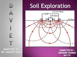
- 54. The electrical resistivity is resistance of the material to the passage of electrical current. D = Distance beween theelectrodes (m) E = Current Flowing between outerelectrodes (amps) I = Potential drop between innerelectrodes (Volts) Each soil has its own resistivitydepending upon its water content, compaction and composition; for example, it is low For saturated silt and high for loose drygravel or solid rock. The test is conducted by driving four metal spikes to serve As electrodes into the ground along a straight lineat equal distance. A directvoltage is imposed between the two outer electrodes, and the potential drop is measured between the innerelectrodes. The mean resistivity Q (ohm-m) is Computed from the expression: I Ώ = 2П D E Ohm-m Abhishek sharma 661/15
- 55. To take undisturbed samples from bore holes properly designed sampling tools are required. These differ for cohesive and non-cohesive soils and for rocks. The fundamental requirement of a sampling tool is that on being forced into the ground it should cause as little displacement, remoulding and disturbance as possible. The degree of disturbance is controlled by the following three features of its design: • Cutting edge • Inside wall friction • Non return value Abhishek sharma 661/15
- 56. Cutting Edge- A typical cutting edge is shown in Fig. 7. It should embody the following features: a) Inside clearance ( CI ) - The internal diameter (Dc) of the cutting edge should be slightly less than that inside dia. of the sample tube (Ds) to give inside clearance. The inside clearance, calculated as follows, should be between 1 percent and 3 percent of the internal diameter of the sample tube. This allows for elastic expansion of the soil as it enters the tube, reduces frictional drag on the sample from the wall of the tube and helps to retain the core. CI = Ds – Dc x 100 Dc b) Outside clearance (Co) = The outside diameter (Dw) of the cutting edge should be slightly larger than the outside diameter (Dt) of the tube to give outside clearance. The outside clearance should not be much greater than the inside clearance. This facilitates the withdrawal of the sampler from the ground. The outside clearance should be calculated as follows: Co = Dw – Dt x 100 Dt Abhishek sharma 661/15
- 57. Area ratio (Ar) - The area ratio, calculated as follows, should be kept as low as possible consistent with the strength requirements of the sample tube. Its value should not be greater than about 20 percent for stiff formations; for soft sensitive clays an area ratio of 10 percent or less should be preferred Where it is not possible to provide sufficient inside clearance, piston sampler should preferably be used: Ar = D2 w – D2 c x 100 D2 c Dw - outside diameter of the cutting shoe DC - inside diameter of the cutting shoe. Dt – outside diameter of sample tube Ds – inside diameter of sample tube Abhishek sharma 661/15
- 58. Wall Friction – This can be reduced by: a) suitable inside clearance, b) a smooth finish to the sample tube, and c) oiling the tube properly. Non-return Valve – The valve should have a large orifice to allow the air and water to escape quickly and easily when driving the sampler. Recovery Ratio - For a satisfactory undisturbed sample, taking into consideration the influence of the inside clearance [ see 4.1.1 (a) ] when excess soil is prevented from entering the tube, the recovery ratio calculated as follows should be between 98 to 96 percent. Rr = L/H L = length of sample within tube H = depth of penetration of sample tube Abhishek sharma 661/15
- 59. Generally used for cohesionless soils To determine relative density , angle of shearing resistance, UCC A bore hole is made using drilling tools After reaching the specified depth, the drilling tool is replaced by a split spoon sampler to collect soil sample. Abhishek sharma 661/15
- 60. First 150 mm penetration is taken as seating drive and the no. of blows required for that penetration is discarded No. of blows required for next 300mm penetration after seating drive is taken as standard penetration number (N). But the condition is that hammer weight should be 63.5kg and height of free fall should be 750 mm No of blows greater than 50 are taken as refusal and the test is discontinued Corrections are applied to the observed N value Abhishek sharma 661/15
- 62. • The sum of the blows for second and third increment of 0.15 m penetration is termed "penetration resistance or "N-value". • If the split spoon sampler is driven less than 45 cm (total), then the penetration resistance shall be for the last 30 cm of penetration (if less than 30 cm is penetrated, the logs should state the number of blows and the depth penetrated). • If the no. of blows for 15cm drive exceeds 50, it is taken as a refusal and the test is discontinued. • Tests shall be made at every change in stratum or at intervals of not more than l-5 m whichever is less. Tests may be made at lesser intervals if specified or considered necessary.
- 63. • Dilatancy Correction • Overburden correction Of these, overburden correction is applied first and to that corrected value, dilatancy Correction is applied Abhishek sharma 661/15
- 64. • In granular soils, overburden pressure affects the penetration resistance • If two soils, having same relative density but different confining pressures are tested, the one with a higher confining pressure gives a higher penetration number as the confining pressure in cohesion less soils increases with the depth, the penetration number for soils at shallow depths is underestimated and that at greater depths is overestimated. • For uniformity, the N- values obtained from field tests under different effective overburden pressures are corrected to a standard effective overburden pressure. Abhishek sharma 661/15
- 67. • One of the most commonly used corrections • According to them, Abhishek sharma 661/15
- 68. FACTORS Attitude of operators Overdrive sampler Sampler plugged by gravel Plugged casing COMMENTS Blow counts for the same soil using the same rig can vary, depending on who is operating the rig, and perhaps the mood of operator and time of drilling. Higher blow counts usually result from an overdriven sampler. Higher blow counts result when gravel plugs the sampler, resistance of loose sand could be highly overestimated. High N-values may be recorded for loose sand when sampling below groundwater table. Hydrostatic pressure can cause sand to rise within the casing. Abhishek sharma 661/15
- 69. FACTORS COMMENTS Inadequate cleaning of the SPT is only partially made in original soil. Sludge may be borehole Not seating the sampler spoon on undisturbed material Driving of the sample spoon above the bottom of the trapped in the sampler and compressed as the sampler is driven, increasing the blow count (This may even prevent sample recovery.) Incorrect N-values obtained. N-values are increased in sands and reduced in cohesive soils. hydrostatic head in boring casing Failure to maintain sufficient The water table in the borehole must be at least equal to the piezometric level in the sand, otherwise the sand at the bottom of the borehole may be transformed into a loose state thereby decreasing the blow countsAbhishek sharma 661/15
- 70. FACTORS COMMENTS Overwashing ahead of casing Low blow count may result for dense sand since overwashing loosens sand. Drilling method Free fall of the drive Weight is not attained Not using correct weight Drilling technique (e.g., cased holes vs. mud stabilized holes) may result in different N-values for the same soil. Using more than 1-1/2 turns of rope around the drum and or using wire cable will restrict the fall of the drive weight. Driller frequently supplies drive hammers with weights varying from the standard by as much as 10 lbs. Abhishek sharma 661/15
- 71. FACTORS COMMENTS Weight does not strike the drive cap concentrically Impact energy is reduced, increasing N-values. Not using a guide rod Incorrect N-value obtained. Not using a good tip on the sampling spoon If the tip is damaged and reduces the opening or increases the end area the N-value can be increased. Use of drill rods heavier than standard With heavier rods more energy is absorbed by the rods causing an increase in the blow count. Abhishek sharma 661/15
- 72. - Relative Density - Effective Stress Friction Angle - Unconfined Compressive Strength *Some correlations require the raw N-values whereas others use the corrected N-values. Abhishek sharma 661/15
- 76. • Relatively quick and simple to perform. • Provides a representative soil sample. • Provides useful index of relative strength and compressibility of the soil. • Able to penetrate dense layers, gravel, and fill. • Numerous case histories of soil liquefaction during past earthquakes are available with SPT N-values. The method based on this history can reflect actual soil behavior during earthquakes, which cannot be simulated in the laboratory. Abhishek sharma 661/15
- 77. • The SPT is an in situ test that reflects soil density, soil fabric, stress and strain history effects, and horizontal effective stress, all of which are known to influence the liquefaction resistance but are difficult to obtain with undisturbed samples. The SPT equipment is rugged, and the test can be performed in a wide range of soil conditions. There are numerous correlations for predicting engineering properties with a good degree of confidence. Abhishek sharma 661/15
- 78. PRECAUTIONS • The drill rods should be of standard specification and should not be in bent condition. • The split spoon sampler must be in good condition and the cutting shoe must be free from wear and tear. • The drop hammer must be of the right weight and the fall should be free, frictionless and vertical. • The height of fall must be exactly 750 mm. Any change from this will seriously affect the N value. Abhishek sharma 661/15
- 79. • The bottom of the borehole must be properly cleaned before the test is carried out. If this is not done, the test gets carried out in the loose, disturbed soil and not in the undisturbed soil. • When a casing is used in borehole, it should be ensured that the casing is driven just short of the level at which the SPT is to be carried out. Otherwise, the test gets carried out in a soil plug enclosed at the bottom of the casing. • When the test is carried out in a sandy soil below the water table, it must be ensured that the water level in the borehole is always maintained slightly above the ground water level. If the water level in the borehole is lower than the ground water level, ‘quick' condition may develop in the soil and very low N values may be recorded. Abhishek sharma 661/15
- 80. REFRENCES: C. VENKATARAMAIAH GEOTECHNICAL ENGINEERING THIRD EDITION ( NEW AGE INTERNATIONAL (P) LTD. PUBLISHERS) A.S.R RAO & GOPAL RANJAN- BASIC AND APPLIED SOIL MECHANICS (NEW AGE INTERNATIONAL (P) LTD., PUBLISHERS) 80ABHISHEK SHARMA 661