Flash butt welding of rails
•Download as PPTX, PDF•
2 likes•1,386 views

Flash butt welding of rails

Recommended
More Related Content
What's hot
What's hot (20)
Similar to Flash butt welding of rails
Similar to Flash butt welding of rails (20)
Recently uploaded
Recently uploaded (20)
Flash butt welding of rails
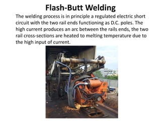
- 1. Flash-Butt Welding The welding process is in principle a regulated electric short circuit with the two rail ends functioning as D.C. poles. The high current produces an arc between the rails ends, the two rail cross-sections are heated to melting temperature due to the high input of current.
- 2. • During the following upset stroke the rails are pressed together under high pressure causing the ends to coalesce. The upset metal is trimmed off immediately after the upset stroke. • The result is an accurate weld without filler metal with a very small heat-affected zone and a more or less consistent progression of the hardening process with a favorable crystal- line structure.
- 3. Preparing the weld – the slight inclination
- 4. Principle of Flash Butt Welding of Rails I. One end of the joint begins moving towards the other. II. Voltage is applied but current is not yet flowing. III. When high spots touch current and rapidly molts the metal at the point of contact. IV. The high current causes rapid expansion which expels the molten metal. V. Heat is also conducted into the area around the point of contact. VI. As the joints keep closing, the next two high spots touch to allow current to flow. VII. As flashing continues, perhaps hundreds of flashes, the joint area is heated. VIII. At the end of the flashing cycle the joint area is at forged welding temperature, ready for ‘butting’. IX. Because the largest proportion of material is in the rail head, this cools down far more slowly. The natural consequence is a depression of the rail in the area of the welded joint. X. However, this result would have very negative effects on the track geometry and the operational safety. For this reason, a slight upward inclination of the two rail ends is performed, adapted to the respective rail profile, so that an ideal position of the rail is achieved when the weld has cooled down.
- 5. Flash Butt Welding & Alumino Thermic Welding a) Alumino Thermic Welding – Strength of AT joint is app. only 56% of parent rail. – More prone to corrosion. – High failure rate. – Poor Quality of Weld. b) Flash Butt Welding – Strength of FB joint is almost equal to parent rail. – Less prone to corrosion – Failure rate < 10 %. – Excellent Quality of Weld. The defects like porosity, inclusions and lack of fusion are eliminated.
- 6. Mobile Flash butt welding Machine I. It is rail cum road machine that can be driven to site. II. The mobile Flash butt welding machines are either built in Standard railway vehicle or as containerized units. III. In case of m/c built on Railway Vehicle the welding head is Positioned between the bogies and can be lowered for welding in running track. IV. The containerized units can be used for welding in track or on cess on the other hand the standard vehicle machine can be used only on running line. V. New machine is fully computerized. VI. Once the welding head is in position, the entire process is carried out automatically at the push of button.
- 7. Welding Parameters – Welding Current, – Upset force Pressure, – Displacement, – Welding time, – Programmed identification and setting details.
- 8. Procedure Approval Tests I. Weld alignment. II. Weld Trimming. III. Weld appearance. IV. Non-Destructive testing. V. Bend testing. VI. Hardness testing. VII. Macro Examination. VIII.Statements of the result and procedures. IX. Maintenance of the records.
- 9. Related Standard • BS EN 14587-2 – Railway applications. Track. Flash butt welding of rails. Prepared By-Sujit Sen, Kolkata(India). Thank You