Water Industry Process Automation & Control Monthly - April 2024
Merchant circle.pptx
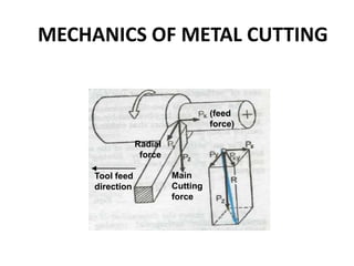
1. MECHANICS OF METAL CUTTING
(feed
force)
Main
Cutting
force
Radial
force
Tool feed
direction
2. Need for calculating forces, velocities and
angles during machining??
• We need to determine the cutting forces in turning for
Estimation of cutting power consumption, which also enables
selection of the power source (e.g. motors) during design of the
machine tools.
• Structural design of the machine – fixture – tool system.
• Evaluation of role of the various machining parameters (tool
material and geometry) on cutting forces to make machining
process more efficient and economical.
• Condition monitoring of the cutting tools and machine tools.
3. Cutting Edge is normal to tool feed.
Here only two force components are
considered i.e. cutting force and thrust
force. Hence known as two dimensional
cutting.
Shear force acts on smaller area.
Cutting Edge is inclined at an acute
angle to tool feed.
Here three force components are
considered i.e. cutting force, radial force
and thrust force. Hence known as three
dimensional cutting.
Shear force acts on larger area.
Metal Cutting is the process of removing unwanted material from the workpiece
in the form of chips
4. Assumptions
(Orthogonal Cutting Model)
The cutting edge is a straight line extending perpendicular
to the direction of motion, and it generates a plane surface
as the work moves past it.
The tool is perfectly sharp (no contact along the clearance
face).
The shearing surface is a plane extending upward from
the cutting edge.
The chip does not flow to either side
The depth of cut/chip thickness is constant uniform
relative to velocity between work and tool
Continuous chip, no built-up-edge (BUE)
6. α : Rake angle
b : Frictional angle
ϕ : Shear angle
Ft : Thrust Force
Fc: Cutting Force
Fs: Shear Force
Fn: Normal Shear Force
F: Frictional Force
N: Normal Frictional Force
V: Cutting velocity
Vc: Chip velocity
Vs: Shear velocity
7. FL
FC
Fr
DIRECTION OF ROTATION
WORKPIECE
CUTTING TOOL
DIRECTION OF FEED
Velocity of
Tool relative to
workpiece V
Longitudinal Force
Radial Force
‘Thrust’ Force
Tangential Force
'Cutting' Force
‘Facing’ Forces For Orthogonal Model
End view
Note: For the 2D Orthogonal Mechanistic
Model we will ignore the Longitudinal
component
8. Orthogonal Cutting Model
(Simple 2D mechanistic model)
Mechanism: Chips produced by the shearing process along the shear plane
a
t0
f
+
Rake
Angle
Chip
Workpiece
Clearance Angle
Shear Angle
t c
depth of cut
Chip thickness
Tool
Velocity V
tool
-
10. tool
Cutting Ratio
(or chip thickness ratio)
As Sinf =
to
AB
and Cosf-a) =
tc
AB
Chip thickness ratio (r) =
t0
tc
=
sinf
cos(fa)
f
tc
to
fa)
A
B
Chip
Workpiece
12. Fs , Resistance to shear of the metal in forming the chip. It
acts along the shear plane.
Fn , ‘Backing up’ force on the chip provided by the
workpiece. Acts normal to the shear plane.
N, It is at the tool chip interface normal to the cutting face of
the tool and is provided by the tool.
F, It is the frictional resistance of the tool acting on the chip.
It acts downward against the motion of the chip as it glides
upwards along the tool face.
Cutting Forces
(2D Orthogonal Cutting)
15. Cutting Forces
• Forces considered in orthogonal cutting include
– Cutting, friction (tool face), and shear forces
• Cutting force,Fc acts in the direction of the cutting
speed V, and supplies the energy required for cutting
– Ratio of Fc to cross-sectional area being cut (i.e. product of
width and depth of cut, t0) is called: specific cutting force
• Thrust force,Ft acts in a direction normal to the cutting
force
• These two forces produces the resultant force, R
• On tool face, resultant force can be resolved into:
– Friction force, F along the tool-chip interface
– Normal force, N to to friction force
15
16. Cutting Forces
• It can also be shown that (b is friction angle)
• Resultant force, R is balanced by an equal and
opposite force along the shear plane
• It is resolved into shear force, Fs and normal force, Fn
• Thus,
• The magnitude of coefficient of friction, is
16
b
b cos
sin R
N
R
F
f
f
f
f
cos
sin
sin
cos
t
c
n
t
c
s
F
F
F
F
F
F
a
a
tan
tan
t
c
c
t
F
F
F
F
N
F
17. Cutting Forces
• The tool holder, work-holding devices, and machine tool
must be stiff to support thrust force with minimal
deflections
– If Ft is too high ⇒ tool will be pushed away from workpiece
– this will reduce depth of cut and dimensional accuracy
• The effect of rake angle and friction angle on the direction
of thrust force is
• Magnitude of the cutting force, Fc is always positive as the
force that supplies the work required in cutting
• However, Ft can be +ve or –ve; i.e. Ft can be upward with
a) high rake angle, b) low tool-chip friction, or c) both
17
)
a
b
sin
R
Ft
18. Forces from Merchant's Circle
Friction Force F = Fcsina + Ftcosa
Normal Force N = Fccosa - Ftsina
Shear Force Fs = Fccosf - Ftsinf
= F/N and = tanb typically 0.5 - 2.0)
Force Normal to Shear plane Fn = Fcsinf + Ftcosf
19. Stresses
On the Shear plane:
Normal Stress = s = Normal Force / Area =
Fn
AB w
=
Fnsinf
tow
Shear Stress = s = Shear Force / Area =
Fs
AB w
=
Fssinf
tow
On the tool rake face:
= Normal Force / Area =
N
tc w
(often assume tc = contact length)
= Shear Force / Area =
F
tc w
20. Power
•Power (or energy consumed per unit time) is the product of force and
velocity. Power at the cutting spindle:
•Power is dissipated mainly in the shear zone and on the rake face:
•Actual Motor Power requirements will depend on machine efficiency
E (%):
Cutting Power Pc = FcV
Power for Shearing Ps = FsVs
Friction Power Pf = FVc
Motor Power Required =
Pc
E
x 100
21. Cutting Forces and Power measurement
Measuring Cutting Forces and Power
• Cutting forces can be measured using a force
transducer, a dynamometer or a load cell mounted
on the cutting-tool holder
• It is also possible to calculate the cutting force from the
power consumption during cutting (provided
mechanical efficiency of the tool can be determined)
• The specific energy (u) in cutting can be used to
calculate cutting forces
21
22. Cutting Forces and Power
Power
22
Prediction of forces is
based largely on
experimental data (right)
Wide ranges of values
is due to differences in
material strengths
Sharpness of the tool tip
also influences forces
and power
Duller tools require
higher forces and power