
Recommended
More Related Content
What's hot
What's hot (19)
Similar to Cpu224 xp eth-ethernet_interface
Similar to Cpu224 xp eth-ethernet_interface (20)
More from arco zhang
Recently uploaded
Recently uploaded (20)
Cpu224 xp eth-ethernet_interface
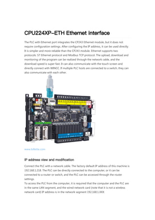
- 1. CPU224XP-ETH Ethernet interface The PLC with Ethernet port integrates the CP243 Ethernet module, but it does not require configuration settings. After configuring the IP address, it can be used directly. It is simpler and more reliable than the CP243 module. Ethernet supports two protocols: S7 Ethernet protocol and Modbus TCP protocol. The upload, download and monitoring of the program can be realized through the network cable, and the download speed is super fast. It can also communicate with the touch screen and directly connect with WINCC. If multiple PLC hosts are connected to a switch, they can also communicate with each other. www.lollette.com IP address view and modification Connect the PLC with a network cable. The factory default IP address of this machine is 192.168.1.218. The PLC can be directly connected to the computer, or it can be connected to a router or switch, and the PLC can be accessed through the router settings. To access the PLC from the computer, it is required that the computer and the PLC are in the same LAN segment, and the wired network card (note that it is not a wireless network card) IP address is in the network segment 192.168.1.XXX
- 2. After filling in the computer’s IP address, test whether the computer and the PLC are physically connected properly. Open the “Command Line Prompt” on the computer, and ping 192.168.1.218. If the PLC returns the data within 1ms, the physical link is normal. View and modify IP address via web page Use a browser (IE browser is recommended) to enter the URL, http://192.168.1.218
- 3. Ethernet download and monitoring Download Take the PLC network cable connected to the computer as an example, click Set PG/PC interfacein the viewing window and choose according to your computer network card (the picture below is the demo machine network card, the user needs to choose according to your computer network card, the name of your computer network card can be viewed in the “device manager”, if the driver list There is no network card in the computer, this is a S7 software compatibility problem, it is recommended to apply a 64-bit system patch), click Diagnose to test.
- 4. OK means that the SR protocol test is successful, but it does not mean that the PLC connection is successful, because even if the PLC is not connected, if the SR protocol is okay, the test will be OK; if it fails, please refer to the “SR Protocol Diagnosis Failure Solution”. Click the communication button on the viewing interface
- 5. Click OK, double-click to refresh the list, the PLC model is identified in the host column, indicating that the connection is successful
- 6. Be sure to click the searched device, and then click Confirm.
- 7. SR protocol diagnosis failure solution An error occurred in the function call SRMD_Set(..) Error: No interface handle Question: S7ONLINE Error: SRMD_Set No interface handle? Reason: “C:Program FilesCommon FilesSiemensS7IEPGs7oiehsx.exe” file is blocked from running, causing: “SIMATIC IEPG Help Service” to stop. MODBUS TCP Protocol-Communication Example Ethernet port PLC, supports Modbut TCP server mode and client mode Install MODBUS TCP command library Open the S7 programming software, there is no Modbus TCP in the library, download the latest Modbus TCP library “S7-200 software Modbus TCP installation library 4.0.m wl“ Solution 1: 1 Right-click on the computer, left-click on Manage—>Services and Applications—>Service—>and then activate "SIMATIC IEPG Help Service"; if it fails to activate, it means that it is blocked by antivirus software. Add the s7oiehsx.exe file to the "antivirus software" "In the executable file trust table, re-run "SIMATIC IEPG Help Service", finally restart the computer, and restart STEP 7. 2 Solution 2: 3 Left-click the mouse and click Start—>Run—>services.msc to activate "SIMATIC IEPG Help Service"; if it fails to activate, it means it is blocked by anti-virus software. Add the s7oiehsx.exe file to the executable file of "360 or other anti-virus software" In the trust list, re-run "SIMATIC IEPG Help Service", finally restart the computer, and restart STEP7. 4
- 8. This library file cannot be deleted after installation, otherwise the library will be lost, so it is recommended to copy it to a fixed location. After restarting, the MODBUS_TCP library is installed MODBUS address mapping table PLC as server, computer (touch screen) as client example The PLC is the server and the touch screen is the client is the most commonly used connection method. It is also the easiest way to program on the PLC. You only need to write a command. Modbus tcp serves as the server, and the port is 502. Modbus address Read/write Description Function code 00001 to 00128 Q0.0 to Q15.7 Digital output Read coil: No. 1 function code; Write single coil: No. 5 function code, Write multiple coils: No. 15 function code 10001 to 10128 I0.0 to I15.7 Digital input Read input status bit:No. 2 Function code 30001 to 30128 AIW0 to AIW62 Analog input register Read input register: No. 4 function code; 40001 to 4XXXX VW(HoldStart) to VW[HoldStart +2 * (XXXX-1)] Holding register, corresponding to V area, HoldStart is filled in the program instruction. 40001 to 4XXXX Read holding register: No. 3 function code; Write a single register: function code No. 6; write multiple registers: function code No. 16
- 9. PLC server command (ModbusTCP_Sever) PLC as client, computer (touch screen) as server setting This kind of use is mainly used in PLC connection with sensor applications that support Modbus TCP protocol. Client instruction (ModbusTCP_Client) Parameter Parameter Type Data Type Definition EN INPUT Bool Enable Port INPUT Byte Communication port 1,2,3,4,5 Error INPUT Byte error code MaxIO INPUT Word The maximum I/Q bit, the maximum number of I/O points involved in communication, the I/O image area of S7-200 is 128/128, and the default value is 128 MaxAI INPUT Word The maximum number of AI words, the maximum number of AI channels involved in communication, can be 16 or 32 MaxHold INPUT Word The largest holding register area, V memory area words involved in communication (VW) Holdstart INPUT DWord The starting address of the holding register area, specified by &VBx (indirect addressing mode)
- 10. Add data in the data block according to the access requirements Parameter Parameter Type Data Type Definition EN INPUT Bool Enable CONNECT INPUT Bool 0: Disconnect, 1: Establish and keep the connection. Socket INPUT Byte Communication port 1,2,3,4,5 Profile_Table INPUT Word The starting address of the communication profile table is represented by a byte offset from V0 (for example, VB99, the corresponding value is 99) Error INPUT Byte Error code
- 11. Send data configuration format Offset address of sending start address example example VBn 4 Number of segments accessed by this socket 4 VBn+1 The highest byte of the other party’s IP address 192 VBn+2 The second byte of the other party’s IP address 168 VBn+3 The third byte of the other party’s IP address 1 VBn+4 The last byte of the other party’s IP address 205 VBn+5 Slave ID Slave address 16#FF VBn+6 function code 3
- 12. The format of the received data VBn+7 The data address of the slave to be read and written 40001 VBn+9 Number of read and write data 4 VBn+11 Start address of sending data in V storage area 1000 VBn+13 Start address of the received data in the V storage area 1300 VBn+15 Status byte of this section VBn+16 to VBn+20 This section reserved for use VBn+21 The highest byte of the other party’s IP address 192 VBn+22 The second byte of the other party’s IP address 168 VBn+23 The third byte of the other party’s IP address 1 VBn+24 The last byte of the other party’s IP address 205 VBn+25 Slave ID Slave address 16#FF VBn+26 function code 16 VBn+27 The data address of the slave to be read and written 41000 VBn+29 Number of read and write data 4 VBn+31 Start address of sending data in V storage area 1600 VBn+33 Start address of the received data in the V storage area 1900 VBn+35 Status byte of this section VBn+36 to VBn+40 This section reserved for use continuous continuous answer Receive the offset address of the start address Description Correct answer VBn Number of received data VBn+1 Slave ID Slave address VBn+2 function code
- 13. In the above example, only the Socket1 communication port is turned on, segment 1 accesses 192.168.1.205, segment 2 accesses 192.168.1.205, segment 3 accesses 192.168.1.210, segment 4 accesses 192.168.1.213, and the same communication port accesses the unreachable IP Address, this will reduce the efficiency of communication. It is recommended that the same socket only access the same IP address. If you want to access another IP address, open another socket for configuration. FAQ Ping fails. Answer: It means that the physical layer is not connected successfully. 1 Check whether the network cable is loose. 2 Check whether the computer IP and PLC’s IP are in the same network segment. 3Whether the computer gateway address, subnet mask and DNS address are filled in completely. 4Turn off the computer’s wireless network card and try. 5 Let the computer and the PLC connect directly with the network cable, and try to remove the intermediate router. It can be pinged, but the web page cannot be opened. Answer: 1 Try changing the IE browser. 2 https is not allowed in the URL, but http should be used. 3 Try changing to another computer. The S7 software settings PC/PG interface cannot find the network card driver. Answer: Download the 64-bit patch from the website and try it out. Two CPU226-ETH devices are hung under the same switch, and one of them is not smooth. Answer: After the PLC leaves the factory, the MAC addresses are all the same. Check if the MAC addresses are the same, and just modify one of them. The two PLCs can’t communicate directly with the network cable, but they can communicate when they are plugged into the switch. Answer: Try changing the crossover cable. VBn+3 Number of data read VBn+4 Data area Error VBn Number of received data VBn+1 Slave ID Slave address VBn+2 function code+0x80 The highest position of the function code 1 VBn+3 Error code: 0 no error 1 The value of Count is 0 2 Illegal data address 4 Communication port is busy 6 Function code error