Model Call Girl in Tilak Nagar Delhi reach out to us at 🔝9953056974🔝
merged (1).pdf
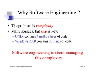
1. Why Software Engineering ?
• The problem is complexity
• Many sources, but size is key:
– UNIX contains 4 million lines of code
Software Engineering Methodologies Slide 1
– UNIX contains 4 million lines of code
– Windows 2000 contains 108 lines of code
Software engineering is about managing
this complexity.
2. What is Software Engineering?
What is Software Engineering?
►
►The process of solving customers’ problems by the
The process of solving customers’ problems by the
systematic development and evolution of large,
systematic development and evolution of large,
high
high-
-quality software systems within cost, time
quality software systems within cost, time
and other constraints
and other constraints
What is Software Engineering?
What is Software Engineering?
•SE
DR.Z
AINA
B N.
NEM
•2
and other constraints
and other constraints
►
►Note:
Note:
Process, systematic (not ad hoc), evolutionary…
Process, systematic (not ad hoc), evolutionary…
Constraints: high quality, cost, time, meets user
Constraints: high quality, cost, time, meets user
requirements
requirements
3. What is software?
• Computer programs and associated documentation
Software Engineering Methodologies Slide 3
• Software products may be developed for a particular
customer or may be developed for a general market
• Software products may be
– Generic - developed to be sold to a range of different
customers
– Bespoke (custom) - developed for a single customer
according to their specification
4. What is software engineering?
Software engineering is an engineering discipline
which is concerned with all aspects of software
production
Software Engineering Methodologies Slide 4
Software engineers should
– adopt a systematic and organised approach to their work
– use appropriate tools and techniques depending on
• the problem to be solved,
• the development constraints and
• the resources available
5. What is the difference between software
engineering and computer science?
Computer Science Software Engineering
is concerned with
the practicalities of
Software Engineering Methodologies Slide 5
Computer science theories are currently
insufficient to act as a complete underpinning
for software engineering
theory
fundamentals
the practicalities of
developing
delivering useful software
ALC1
7. What is the difference between software
engineering and system engineering?
• System engineering is concerned with all aspects
of computer-based systems development including
hardware, software and process engineering
Software Engineering Methodologies Slide 6
• Software engineering is part of this process
• System engineers are involved in
system specification, architectural design,
integration and deployment
8. What is a software process?
• A set of activities whose goal is the
development or evolution of software
• Generic activities in all software processes are:
Software Engineering Methodologies Slide 7
• Generic activities in all software processes are:
– Specification - what the system should do and its
development constraints
– Development - production of the software
system(design +program).
– Validation - checking that the software is what the
customer wants
– Evolution - changing the software in response to
changing demands
9. What is a software process model?
A simplified representation of a software process,
presented from a specific perspective
• Examples of process perspectives:
Workflow perspective represents inputs, outputs and dependencies
Data-flow perspective represents data transformation activities
Software Engineering Methodologies Slide 8
Data-flow perspective represents data transformation activities
Role/action perspective represents the roles/activities of the
people involved in software process
• Generic process models
– Waterfall
– Evolutionary development
– Formal transformation
– Integration from reusable components
10. What are the costs of software
engineering?
• Roughly 60% of costs are development costs,
40% are testing costs. For custom software, evolution
costs often exceed development costs
Software Engineering Methodologies Slide 9
• Costs vary depending on the1- type of system being
developed and 2-the requirements of system
attributes such as performance and system reliability
• Distribution of costs depends on the development
model that is used
11. What are software engineering
methods?
Structured approaches to software development
which include system models, notations, rules, design
advice and process guidance
Software Engineering Methodologies Slide 10
• Model descriptions (Descriptions of graphical
models which should be produced)
• Rules (Constraints applied to system models)
• Recommendations (Advice on good design practice)
• Process guidance (What activities to follow)
12. What is CASE ?
(Computer-Aided Software Engineering)
Software systems which are intended to provide
automated support for software process activities, such
as requirements analysis, system modelling, debugging
and testing
Software Engineering Methodologies Slide 11
• Upper-CASE
– Tools to support the early process
activities of requirements and design
• Lower-CASE
– Tools to support later activities such as
programming, debugging and testing
13. What are the attributes of good
software?
• Maintainability
The software should deliver the required functionality
and performance to the user and should be
maintainable, dependable and usable
Software Engineering Methodologies Slide 12
• Maintainability
– Software must evolve to meet changing needs
• Dependability
– Software must be trustworthy
• Efficiency
– Software should not make wasteful use of system resources
• Usability
– Software must be usable by the users for which it was designed
14. What are the key challenges
facing software engineering?
Software engineering in the 21st century faces
three key challenges:
• Legacy systems
– Old, valuable systems must be maintained and updated
Software Engineering Methodologies Slide 13
– Old, valuable systems must be maintained and updated
• Heterogeneity
– Systems are distributed and include
a mix of hardware and software
• Delivery
– There is increasing pressure
for faster delivery of software
15. Professional and ethical
responsibility
• Software engineering involves wider responsibilities
than simply the application of technical skills
• Software engineers must behave in an honest and
Software Engineering Methodologies Slide 14
• Software engineers must behave in an honest and
ethically responsible way if they are to be respected
as professionals
• Ethical behaviour is more than
simply upholding the law
53. Chapter 5 System modeling
3. Structural Models
Structural models of software display the organization
of a system in terms of the components and their
relationships.
Structural models may be static models, which show the
structure of the system design, or dynamic models,
which show the organization of the system when it is
executing.
Structural models are created when discussing and
designing the system architecture.
2
54. Chapter 5 System modeling
Class Diagrams
Class diagrams are used when developing an object-oriented
system model to show the classes in a system and the
associations between these classes.
An association is a link between classes that indicates that
there is some relationship between these classes.
When you are developing models during the early stages of
the software engineering process, objects represent
something in the real world, such as a patient, a
prescription, doctor, a device, etc.
We have spoken in terms of 'nouns' or 'things.'
3
55. Chapter 5 System modeling
UML classes and association
4
Here we are also showing multiplicity: one object of type Patient is related to one object of type Patient Record
56. Chapter 5 System modeling
The Consultation Class (There are all kinds of
classes: domain / entity classes; software
classes, and many 'levels' of these!
5
This is a high level class – perhaps
a first or second cut at class definition.
Notice much is missing, such as
parameters, returns, etc. from the
methods.
These are ‘software classes’ because
they contain methods (that is, how the
attributes will be used / manipulated.)
Finer levels of granularity are needed
to address the shortcomings of this
class.
But this is a very good way to start your
analysis and class definition, especially
when trying to develop classes from
use cases, where nouns (Consultation)
and verbs (new, prescribe….) will be
found in the use case itself.
57. Chapter 5 System modeling
Generalization
Generalization is an everyday technique that we use to
Rather than learn the detailed characteristics of every entity that
we experience, we place these entities in more general classes
(animals, cars, houses, etc.) and learn the characteristics of these
classes.
This allows us to infer that different members of these classes have
some common characteristics e.g. squirrels and rats are rodents.
In programming, we refer to this as 'inheritance.'
Base class and derived classes, or super class and derived
class.... parent and child.... many terms for capturing these
important relationships.
6
58. Chapter 5 System modeling
Generalization
In modeling systems, it is often useful to examine the classes in a system to
see if there is scope for generalization.
In object-oriented languages, such as Java, generalization is implemented
using the class inheritance mechanisms built into the language.
In a generalization, the attributes and operations associated with higher-level
classes are also associated with (inherited by) the lower-level classes.
The lower-level classes are subclasses inherit the attributes and operations
from their superclasses. These lower-level classes then add more specific
attributes and operations.
7
59. Relationships: Generalization
A relationship among classes where one class shares the
structure and/or behavior of one or more classes
Defines a hierarchy of abstractions in which a subclass
inherits from one or more superclasses
Single inheritance
Multiple inheritance
Generalization is an “is-a-kind of” relationship, or simply,
“is_a” relationship.
61. Airplane Helicopter Wolf Horse
FlyingThing Animal
Bird
multiple
inheritance
Use multiple inheritance only when needed, and
always with caution !
Example: Multiple Inheritance
A class can inherit from several other classes
62. Inheritance leverages the similarities among classes
What Gets Inherited?
A subclass inherits its parent’s attributes, operations,
and relationships
A subclass may:
Add additional attributes, operations, relationships
Redefine inherited operations (use caution!)
Common attributes, operations, and/or relationships
are shown at the highest applicable level in the
hierarchy
64. Chapter 5 System modeling
Object class aggregation models
An aggregation model shows how classes that are
collections are composed of other classes.
Aggregation models are similar to the part-of relationship
in semantic data models.
13
67. Student Schedule
Whole
Aggregation
This is sometimes
called a ‘has_a’
relationship
Part
Relationships: Aggregation
A special form of association that models a whole-part
relationship between an aggregate (the whole) and
its parts
70. Chapter 5 System modeling
Key points
Structural models show the organization and architecture of a
system. Class diagrams are used to define the static structure of
classes in a system and their associations.
19
71. Chapter 5 System modeling
4. Behavioral Models
Behavioral models are models of the dynamic behavior of
a system as it is executing. They show what happens or
what is supposed to happen when a system responds to
a stimulus from its environment.
You can think of these stimuli as being of two types:
A. Data Some data arrives that has to be processed by the
system.
B. Events Some event happens that triggers system processing.
Events may have associated data, although this is not always the
case.
20
72. Chapter 5 System modeling
A. Data-driven Modeling
Many business systems are data-processing systems that
are primarily driven by data.
They are controlled by the data input to the system, with relatively
little external event processing.
Data-driven models show the sequence of actions involved
in processing input data and generating an associated
output.
They are particularly useful during the analysis of
requirements as they can be used to show end-to-end
processing in a system.
21
73. Chapter 5 System modeling
An Activity Model of the insulin pump’s operation
22
These are used a lot!
They are not flowcharts or flowgraphs; merely ‘activities’ that need to
or must take place.
(This is an example (later) of a Pipe-Filter Architectural Model)
74. Chapter 5 System modeling
Order Processing – Sequence Diagram -
behavorial
23
Shows the Sequence of events over time as messages are issued from one object to
another.
Terms: life of the object; lifelines, actors, unnamed objects, recursion, and more.
Very Important to show the scenarios in motion. Dynamic!
75. Chapter 5 System modeling
B. Event-Driven Modeling
Real-time systems are often event-driven, with minimal
data processing.
For example, a landline phone switching system responds to
events such as ‘receiver off hook’ by generating a dial tone.
Event-driven modeling shows how a system responds
to external and internal events.
It is based on the assumption that a system has a finite
number of states and that events (stimuli) may cause a
transition from one state to another.
24
76. Chapter 5 System modeling
State Machine Models
These model the behaviour of the system in response to
external and internal events.
They show the system’s responses to stimuli so are often used
for modeling real-time systems.
State machine models show system states as nodes and
events as arcs between these nodes. When an event occurs,
the system moves from one state to another.
Statecharts are an integral part of the UML and are used to
represent state machine models.
25
77. Key points
Behavioral models are used to describe the dynamic behavior
of an executing system. This behavior can be modeled from
the perspective of the data processed by the system, or by the
events that stimulate responses from a system.
Activity diagrams may be used to model the processing of
data, where each activity represents one process step.
State diagrams are used to model a system’s behavior in
response to internal or external events.
Model-driven engineering is an approach to software
development in which a system is represented as a set of
models that can be automatically transformed to executable
code.
26
78. DR ZAINAB N.NEMER
Key points
Behavioral models are used to describe the dynamic behavior
of an executing system. This behavior can be modeled from
the perspective of the data processed by the system, or by the
events that stimulate responses from a system.
Activity diagrams may be used to model the processing of
data, where each activity represents one process step.
State diagrams are used to model a system’s behavior in
response to internal or external events.
27
80. What is UML?
• Unified Modeling Language
• UML is a modeling language to express and
design documents, software
– Independent of implementation language
DR.ZAINAB N.NEMMER 2
82. UML Baseline
• Use Case Diagrams
• Class Diagrams
• Package Diagrams
• Interaction Diagrams
– Sequence
– Collaboration
• Activity Diagrams
• State Transition Diagrams
• Deployment Diagrams
DR.ZAINAB N.NEMMER 4
83. Use Case Diagrams
• Used during requirements
elicitation to represent external
behavior
• Actors represent roles, that is, a
type of user of the system
• Use cases represent a sequence of
interaction for a type of
functionality; summary of
scenarios
• The use case model is the set of all
use cases. It is a complete
description of the functionality of
the system and its environment
Passenger
PurchaseTicket
DR.ZAINAB N.NEMMER 5
84. Actors
• An actor models an external entity which
communicates with the system:
– User
– External system
– Physical environment
• An actor has a unique name and an optional
description.
• Examples:
– Passenger: A person in the train
– GPS satellite: Provides the system with GPS
coordinates
Passenger
DR.ZAINAB N.NEMMER 6
85. Use Case
A use case represents a class of functionality
provided by the system as an event flow.
A use case consists of:
• Unique name
• Participating actors
• Entry conditions
• Flow of events
• Exit conditions
• Special requirements
PurchaseTicket
DR.ZAINAB N.NEMMER 7
86. Use Case Diagram: Example
Name: Purchase ticket
Participating actor: Passenger
Entry condition:
• Passenger standing in front of
ticket distributor.
• Passenger has sufficient
money to purchase ticket.
Exit condition:
• Passenger has ticket.
Event flow:
1. Passenger selects the number
of zones to be traveled.
2. Distributor displays the amount
due.
3. Passenger inserts money, of at
least the amount due.
4. Distributor returns change.
5. Distributor issues ticket.
Anything missing?
Exceptional cases!
DR.ZAINAB N.NEMMER 8
87. The extends Relationship
• extends relationships represent
exceptional or seldom invoked cases.
• The exceptional event flows are
factored out of the main event flow for
clarity.
• Use cases representing exceptional
flows can extend more than one use
case.
• The direction of a extends
relationship is to the extended use case
Passenger
PurchaseTicket
TimeOut
extends
NoChange
extends
OutOfOrder
extends
Cancel
extends
DR.ZAINAB N.NEMMER 9
88. The includes
Relationship
• includes relationship
represents behavior that is
factored out of the use case.
• includes behavior is
factored out for reuse, not because
it is an exception.
• The direction of a
includes relationship is to
the using use case (unlike
extends relationships).
Passenger
PurchaseSingleTicket
PurchaseMultiCard
NoChange
extends
Cancel
extends
includes
CollectMoney
includes
DR.ZAINAB N.NEMMER 10
89. Use Cases are useful for…
• Determining requirements
– New use cases often generate new requirements as the
system is analyzed and the design takes shape.
• Communicating with clients
– Their notational simplicity makes use case diagrams a good
way for developers to communicate with clients.
– May require some explanation.
• Generating test cases
– The collection of scenarios for a use case may suggest a
suite of test cases for those scenarios.
DR.ZAINAB N.NEMMER 11
90. Class Diagrams
• Gives an overview of a system by showing its
classes and the relationships among them.
– Class diagrams are static
– they display what interacts but not what happens
when they do interact
• Also shows attributes and operations of each
class
• Good way to describe the overall architecture
of system components
DR.ZAINAB N.NEMMER 12
91. Classes – Not Just for Code
• A class represent a concept
• A class encapsulates state (attributes) and behavior (operations).
• Each attribute has a type.
• Each operation has a signature.
• The class name is the only mandatory information.
zone2price
getZones()
getPrice()
TariffSchedule
Table zone2price
Enumeration getZones()
Price getPrice(Zone)
TariffSchedule
Name
Attributes
Operations
Signature
TariffSchedule
DR.ZAINAB N.NEMMER 13
92. Instances
• An instance represents a phenomenon.
• The name of an instance is underlined and can
contain the class of the instance.
• The attributes are represented with their values.
zone2price = {
{‘1’, .20},
{‘2’, .40},
{‘3’, .60}}
tarif_1974:TariffSchedule
DR.ZAINAB N.NEMMER 14
93. UML Class Notation
• A class is a rectangle divided into three parts
– Class name
– Class attributes (i.e. data members, variables)
– Class operations (i.e. methods)
• Modifiers
– Private: -
– Public: +
– Protected: #
– Static: Underlined (i.e. shared among all members of the class)
• Abstract class: Name in italics
DR.ZAINAB N.NEMMER 15
95. Unary Association
A knows about B, but B knows nothing about A
Arrow points in direction
of the dependency
myB.service();
DR.ZAINAB N.NEMMER 17
96. Aggregation
Aggregation is an association with a “collection-member” relationship
void doSomething()
aModule.service();
Hollow diamond on
the Collection side
No sole ownership implied
DR.ZAINAB N.NEMMER 18
97. Composition
Composition is Aggregation with:
Lifetime Control (owner controls construction, destruction)
Part object may belong to only one whole object
Filled diamond on
side of the Collection
members[0] =
new Employee();
…
delete members[0];
DR.ZAINAB N.NEMMER 19
99. UML Multiplicities
Multiplicities Meaning
0..1
zero or one instance. The notation n . . m
indicates n to m instances.
0..* or *
no limit on the number of instances
(including none).
1 exactly one instance
1..* at least one instance
Links on associations to specify more details about the relationship
DR.ZAINAB N.NEMMER 21
101. Association Details
• Can assign names to the ends of the
association to give further information
+getName
() :string
+setName()
-calcInternalStuff
(in x : byte, in y : decimal
)
-Name : string
+ID : long
#Salary: double
-adfaf : bool
Employee
-members: Employee
Team -
group
1
-
individual
*
DR.ZAINAB N.NEMMER 23
102. Static vs. Dynamic Design
• Static design describes code structure and object
relations
– Class relations
– Objects at design time
– Doesn’t change
• Dynamic design shows communication between
objects
– Similarity to class relations
– Can follow sequences of events
– May change depending upon execution scenario
– Called Object Diagrams
DR.ZAINAB N.NEMMER 24
103. Sequence Diagram Format
Actor from
Use Case Objects
1
2
3
4
Lifeline Calls = Solid Lines
Returns = Dashed Lines
Activation
DR.ZAINAB N.NEMMER 25
104. Sequence Diagram : Timing
Slanted Lines show propagation delay of messages
Good for modeling real-time systems
If messages cross this is usually problematic – race conditions
DR.ZAINAB N.NEMMER 26
106. Activity Diagrams
• Fancy flowchart
– Displays the flow of activities involved in a single process
– States
• Describe what is being processed
• Indicated by boxes with rounded corners
– Swim lanes
• Indicates which object is responsible for what activity
– Branch
• Transition that branch
• Indicated by a diamond
– Fork
• Transition forking into parallel activities
• Indicated by solid bars
– Start and End
DR.ZAINAB N.NEMMER 28
107. Sample Activity Diagram
• Ordering System
• May need multiple
diagrams from other
points of view
DR.ZAINAB N.NEMMER 29
109. 6. Software Lifecycle Models
A software lifecycle model is a standardised
format for
• planning
• organising, and
• running
a new development project.
DR.ZAINAB N.NEMER CHAP5 1
110. Software Engineering Methods
• Methods usually provide a notation and vocabulary,
procedures for performing identifiable tasks, and guidelines
for checking both the process and the product
• These are categorized as
Heuristic methods
dealing with informal approaches.
Formal methods
dealing with mathematically based approaches.
Prototyping methods
dealing with software engineering approaches based on various
forms of prototypings
111. Heuristic Methods
• These are categories as
Structured methods
The system is built from a functional viewpoint, starting with a high-level view
and progressively refining this into a more detailed design.
Data-oriented methods
the starting points are the data structures that a program manipulates
rather than the function it performs
Object-oriented methods
The system is viewed as a collection of objects rather than functions
Domain-specific methods
includes specialized methods for developing systems which
involve real-time, safety, or security aspects
112. Formal Methods
• These are categorized as
Specification languages and notations
This topic concerns the specification notation or language
used. Specification languages can be classified as model-
oriented, property-oriented, or behavior-oriented
Refinement
This topic deals with how the method refines (or transforms)
the specification into a form which is closer to the desired final
form of an executable program.
Verification/Proving properties:
This topic covers the verification properties that are specific to
the formal approach, including both theorem proving and
model checking
113. Prototyping Methods
• These are categorized as
Prototyping styles
The prototyping styles topic identifies the various approaches:
throwaway, evolutionary, and executable specification
Prototyping targets
Examples of the targets of a prototyping method may be
requirements, architectural design, or the user interface
Prototyping evaluation techniques
This topic covers the ways in which the results of a
prototype exercise are used.s
115. A project plan contains much information,
but must at least describe:
• resources needed
(people, money, equipment, etc)
• dependency timing of work
(flow graph, work packages)
• rate of delivery (reports, code, etc)
It is impossible to measure rate of progress
except with reference to a plan.
DR.ZAINAB N.NEMER CHAP5 7
116. 6.3. What is a Lifecycle Model?
Definition.
A (software/system) lifecycle model is a
description of the sequence of activities
carried out in an SE project, and the relative
order of these activities.
DR.ZAINAB N.NEMER CHAP5 8
117. There are hundreds of different lifecycle models
to choose from, e.g:
• waterfall,
• code-and-fix
• spiral
• rapid prototyping
• unified process (UP)
• agile methods, extreme programming (XP)
• COTS …
but many are minor variations on a smaller
number of basic models.
DR.ZAINAB N.NEMER CHAP5 9
119. 6.4. The Waterfall Model
• The waterfall model is the classic lifecycle
model – it is widely known, understood
and (commonly?) used.
• In some respect, waterfall is the ”common
sense” approach.
• Introduced by Royce 1970.
DR.ZAINAB N.NEMER CHAP5 11
121. User Requirements
Software Requirements
Architecture Design
Detailed design Coding
Testing
Delivery
The Waterfall
Lifecycle Workflow
Time
User Requirements Document
Software Requirements
Document
Architectural Design
Document
Detailed
Design
Code
phase
output
”Swimming
upstream”
DR.ZAINAB N.NEMER CHAP5 13
122. Advantages
1. Easy to understand and implement.
2. Widely used and known (in theory!)
3. Reinforces good habits: define-before- design,
design-before-code
4. Identifies deliverables and milestones
5. Document driven, URD, SRD, … etc. Published
documentation standards, e.g. PSS-05.
6. Works well on mature products and weak teams.
DR.ZAINAB N.NEMER CHAP5 14
123. Disadvantages I
1. Idealised, doesn’t match reality well.
2. Doesn’t reflect iterative nature of
exploratory development.
3. Unrealistic to expect accurate
requirements so early in project
4. Software is delivered late in project,
delays discovery of serious errors.
DR.ZAINAB N.NEMER CHAP5 15
124. Disadvantages II
5. Difficult to integrate risk management
6. Difficult and expensive to make changes
to documents, ”swimming upstream”.
7. Significant administrative overhead,
costly for small teams and projects.
DR.ZAINAB N.NEMER CHAP5 16
125. Advantages
1. No administrative overhead
2. Signs of progress (code) early.
3. Low expertise, anyone can use it!
4. Useful for small “proof of concept”
projects, e.g. as part of risk reduction.
DR.ZAINAB N.NEMER CHAP5 17
126. Disadvantages
1. Dangerous!
1. No visibility/control
2. No resource planning
3. No deadlines
4. Mistakes hard to detect/correct
2. Impossible for large projects,
communication breakdown, chaos.
DR.ZAINAB N.NEMER CHAP5 18
127. 6.7. Rapid Prototyping
Key idea: Customers are non-technical and
usually don’t know what they want/can have.
Rapid prototyping emphasises requirements
analysis and validation, also called:
• customer oriented development,
• evolutionary prototyping
DR.ZAINAB N.NEMER CHAP5 19
128. Requirements Capture
Quick Design
Build Prototype
Customer Evaluation of
Prototype
Engineer Final
Product
The Rapid
Prototype Workflow
Iterate
DR.ZAINAB N.NEMER CHAP5 20
129. Advantages
1. Reduces risk of incorrect user requirements
2. Good where requirements are
changing/uncommitted
3. Regular visible progress aids management
4. Supports early product marketing
DR.ZAINAB N.NEMER CHAP5 21
130. Disadvantages I
1. An unstable/badly implemented prototype
often becomes the final product.
2. Requires extensive customer collaboration
– Costs customers money
– Needs committed customers
– Difficult to finish if customer withdraws
– May be too customer specific, no broad
market
DR.ZAINAB N.NEMER CHAP5 22
131. Disadvantages II
3. Difficult to know how long project will
last
4. Easy to fall back into code-and-fix
without proper requirements analysis,
design, customer evaluation and feedback.
DR.ZAINAB N.NEMER CHAP5 23
132. Agile (XP) Manifesto
XP = Extreme Programming emphasises:
• Individuals and interactions
– Over processes and tools
• Working software
– Over documentation
• Customer collaboration
– Over contract negotiation
• Responding to change
– Over following a plan
DR.ZAINAB N.NEMER CHAP5 24
133. 6.8.1. Agile Principles
(Summary)
• Continuous delivery of software
• Continuous collaboration with customer
• Continuous update according to changes
• Value participants and their interaction
• Simplicity in code, satisfy the spec
DR.ZAINAB N.NEMER CHAP5 25
134. 6.9. XP Practices (Summary)
• Programming in pairs
• Test driven development
• Continuous planning, change , delivery
• Shared project metaphors, coding standards
and ownership of code
• No overtime! (Yeah right!)
DR.ZAINAB N.NEMER CHAP5 26
135. Advantages
• Lightweight methods suit small-medium
size projects
• Produces good team cohesion
• Emphasises final product
• Iterative
• Test based approach to requirements and
quality assurance
DR.ZAINAB N.NEMER CHAP5 27
136. Disadvantages
• Difficult to scale up to large projects where
documentation is essential
• Needs experience and skill if not to
degenerate into code-and-fix
• Programming pairs is costly
• Test case construction is a difficult and
specialised skill.
DR.ZAINAB N.NEMER CHAP5 28
137. 6.11. COTS
• COTS =
Commercial Off-The-Shelf software
• Engineer together a solution from existing
commercial software packages using
minimal software ”glue”.
• E.g. using databases, spread sheets, word
proccessors, graphics software, web
browsers, etc.
DR.ZAINAB N.NEMER CHAP5 29
138. Advantages
• Fast, cheap solution
• May give all the basic functionality
• Well defined project, easy to run
Disadvantages
• Limited functionality
• Licensing problems, freeware, shareware,
etc.
• License fees, maintainance fees, upgrade
compatibility problems
DR.ZAINAB N.NEMER CHAP5 30
140. [ §1 : 2 ]
Requirements in Context
Requirements may vary
in level of abstraction, contents
from one context to another
System requirements
result from an analysis or discovery
process
Software requirements
result from a design process
involving requirements allocation
Sometimes there is no distinction
between them
Requirements
definition
System
design
Software
design
system
requirements
software
requirements
constraints
problem
needs
DR.ZAINAB N.NEMER
141. [ §1 : 3 ]
Terminology
A requirement is a technical objective which is imposed upon
the software, i.e., anything that might affect the kind of software
that is produced
A requirement may be imposed by
the customer
the developer
the operating environment
The source, rationale, and nature of the requirement must be
documented
Requirements fall into two broad categories
functional
non-functional
DR.ZAINAB N.NEMER
142. [ §1 : 4 ]
Functional Requirements
Functional requirements are concerned with what the software
must do
capabilities, services, or operations
Functional requirements are not concerned with how the
software does things, i.e., they must be free of design
considerations
Functional requirements are incomplete unless they capture all
relevant aspects of the software’s environment
they define the interactions between the software and the
environment
the environment may consist of users, other systems, support
hardware, operating system, etc.
the system/environment boundary must be defined
DR.ZAINAB N.NEMER
143. [ §1 : 5 ]
Non-Functional Requirements
Non-functional requirements place restrictions on the
range of acceptable solutions
Non-functional requirements cover a broad range of
issues
interface constraints
performance constraints
operating constraints
life-cycle constraints
economic constraints
political constraints
manufacturing
DR.ZAINAB N.NEMER
144. [ §1 : 6 ]
Software Requirements
Specification (SRS)
Point of origin
elicitation and/or allocation
activity
Purpose
provide a baseline for all
software development activities
Focus
software/environment
interactions
technical reformulation of
constraints
Nature
highly technical
Usage
design
testing
technical studies
DR.ZAINAB N.NEMER
146. [ §1 : 8 ]
Traceability
Traceability is a property of the software development process
refers to the ability to relate elements of a specification to those
design components that ensure their satisfiability
relations that are precise and narrow in scope simplify analysis
relations that are diffused often entail complex analysis
Specifications may be
functional or non-functional
part of the system requirements or the byproduct of design
Traceability is a useful tool, but not a substitute for verification
Most traceability chains run through the software architecture
requirements to design
design to code
DR.ZAINAB N.NEMER
147. [ §1 : 9 ]
Requirements Verification
Requirements verification is an activity directed
towards the discovery of specification errors
The ultimate goal is to ensure that the specification
(when considered on its own) is
correct
consistent
complete
The verification must be carried out against a model
(formal or informal)
Formal and semi-formal specifications can be
checked out by tools
DR.ZAINAB N.NEMER
148. [ §1 : 10 ]
Requirements Validation
Concerned with establishing
that specified requirements
represent the needs of the
customer and/or user
Needs are not reflected by
any model or document
Thus, validation cannot be
performed in a mechanical way
Good communication is
the key to a successful
validation
well-defined terminology
well-written and simple
specifications
formal reviews
rapid prototypes
simulations
DR.ZAINAB N.NEMER
149. [ §1 : 11 ]
Data Flow Models
Dataflow diagram notation
functions—deterministic
input/output transformations
triggered by the presence of
all needed inputs
flows—unbounded queues
stores—global system data
terminators—interface
models
minispecs—semantics of
the lowest level functions
verify
customer
update
stock
update
customer
data
prepare
order
inventory
mailing
address
customer
file
item
item
profile
order
phone
order
shipping
operator
customers
DR.ZAINAB N.NEMER
150. [ §1 : 12 ]
uses
extends
authorization
phone call
charging
Use Case Models
Actors
model the environment and the
users
initiate activity by providing
stimuli
can be primary or secondary
Use cases
are complete courses of action
initiated by actors (basic or
alternative)
can be extended by (interrupt
analogy) or use other use cases
(call analogy)
DR.ZAINAB N.NEMER
151. [ §1 : 13 ]
Architecture Design Phase
Technical goals
Identify the principal components that make up
the system and their (internal and external)
interfaces
Ensure compliance with respect to expectations
captured in the requirements specification
Understand, assess, and control risks
Ensure predictability of the development process
through accurate planning
DR.ZAINAB N.NEMER
152. [ §1 : 14 ]
Concluding Remarks
Development of software based systems is complex
multiple perspectives
different notations
significant and sophisticated analysis
Requirements elicitation and specification should
focus on communication among people
Requirements must be traceable through the
architecture to the code itself (and vice versa)
The design process should focus mainly on
fundamentals and on the creative activities
DR.ZAINAB N.NEMER
170. 2
11.1 What is Project Management?
Project management encompasses all the activities
needed to plan and execute a project:
• Deciding what needs to be done
• Estimating costs
• Ensuring there are suitable people to undertake the
project
• Defining responsibilities
• Scheduling
• Making arrangements for the work
• continued ...
171. 3
What is Project Management?
• Directing
• Being a technical leader
• Reviewing and approving decisions made by others
• Building morale and supporting staff
• Monitoring and controlling
• Co-ordinating the work with managers of other projects
• Reporting
• Continually striving to improve the process
172. 4
11.2 Software Process Models
Software process models are general approaches for
organizing a project into activities.
• Help the project manager and his or her team to decide:
—What work should be done;
—In what sequence to perform the work.
• The models should be seen as aids to thinking, not rigid
prescriptions of the way to do things.
• Each project ends up with its own unique plan.
174. 6
The waterfall model
The classic way of looking at S.E. that accounts for the
importance of requirements, design and quality assurance.
• The model suggests that software engineers should work in
a series of stages.
• Before completing each stage, they should perform quality
assurance (verification and validation).
• The waterfall model also recognizes, to a limited extent,
that you sometimes have to step back to earlier stages.
175. 7
Limitations of the waterfall model
• The model implies that you should attempt to complete a
given stage before moving on to the next stage
—Does not account for the fact that requirements
constantly change.
—It also means that customers can not use anything
until the entire system is complete.
• The model makes no allowances for prototyping.
• It implies that you can get the requirements right by
simply writing them down and reviewing them.
• The model implies that once the product is finished,
everything else is maintenance.
177. 9
The phased-release model
It introduces the notion of incremental development.
• After requirements gathering and planning, the project
should be broken into separate subprojects, or phases.
• Each phase can be released to customers when ready.
• Parts of the system will be available earlier than when
using a strict waterfall approach.
• However, it continues to suggest that all requirements be
finalized at the start of development.
179. 11
The evolutionary model
It shows software development as a series of hills, each
representing a separate loop of the spiral.
• Shows that loops, or releases, tend to overlap each other.
• Makes it clear that development work tends to reach a
peak, at around the time of the deadline for completion.
• Shows that each prototype or release can take
—different amounts of time to deliver;
—differing amounts of effort.
181. 13
The concurrent engineering model
It explicitly accounts for the divide and conquer
principle.
• Each team works on its own component, typically
following a spiral or evolutionary approach.
• There has to be some initial planning, and periodic
integration.
182. 14
Choosing a process model
• From the waterfall model:
—Incorporate the notion of stages.
• From the phased-release model:
—Incorporate the notion of doing some initial high-level analysis,
and then dividing the project into releases.
• From the spiral model:
—Incorporate prototyping and risk analysis.
• From the evolutionary model:
—Incorporate the notion of varying amounts of time and work,
with overlapping releases.
• From concurrent engineering:
—Incorporate the notion of breaking the system down into
components and developing them in parallel.
183. 15
11.3 Cost estimation
To estimate how much software-engineering time will be
required to do some work.
• Elapsed time
—The difference in time from the start date to the end
date of a task or project.
• Development effort
—The amount of labour used in person-months or
person-days.
—To convert an estimate of development effort to an
amount of money:
You multiply it by the weighted average cost (burdened cost)
of employing a software engineer for a month (or a day).
184. 16
Principles of effective cost estimation
Principle: Include all activities when making estimates.
• The time required for all development activities must be
taken into account.
• Including:
- Prototyping
- Design
- Inspecting
- Testing
- Debugging
- Writing user documentation
- Deployment.
185. 17
11.4 Building Software Engineering Teams
Software engineering is a human process.
• Choosing appropriate people for a team, and assigning
roles and responsibilities to the team members, is
therefore an important project management skill
• Software engineering teams can be organized in many
different ways
a) Egoless b) Chief programmer c) Strict hierarchy
186. 18
Software engineering teams
Egoless team:
• In such a team everybody is equal, and the team works
together to achieve a common goal.
• Decisions are made by consensus.
• Most suited to difficult projects with many technical
challenges.
187. 19
Software engineering teams
Hierarchical manager-subordinate structure:
• Each individual reports to a manager and is responsible
for performing the tasks delegated by that manager.
• Suitable for large projects with a strict schedule where
everybody is well-trained and has a well-defined role.
• However, since everybody is only responsible for their
own work, problems may go unnoticed.
188. 20
Software engineering teams
Chief programmer team:
• Midway between egoless and hierarchical.
• The chief programmer leads and guides the project.
• He or she consults with, and relies on, individual
specialists.
189. 21
Choosing an effective size for a team
• For a given estimated development effort, in person
months, there is an optimal team size.
—Doubling the size of a team will not halve the
development time.
• Subsystems and teams should be sized such that the total
amount of required knowledge and exchange of
information is reduced.
• For a given project or project iteration, the number of
people on a team will not be constant.
• You can not generally add people if you get behind
schedule, in the hope of catching up.
190. 22
Skills needed on a team
• Architect
• Project manager
• Configuration management and build specialist
• User interface specialist
• Technology specialist
• Hardware and third-party software specialist
• User documentation specialist
• Tester
191. 23
11.5 Project Scheduling and Tracking
• Scheduling is the process of deciding:
—In what sequence a set of activities will be
performed.
—When they should start and be completed.
• Tracking is the process of determining how well you are
sticking to the cost estimate and schedule.
192. 24
PERT charts
A PERT chart shows the sequence in which tasks must
be completed.
• In each node of a PERT chart, you typically show the
elapsed time and effort estimates.
• The critical path indicates the minimum time in which it
is possible to complete the project.
194. 26
Gantt charts
A Gantt chart is used to graphically present the start
and end dates of each software engineering task
• One axis shows time.
• The other axis shows the activities that will be
performed.
• The black bars are the top-level tasks.
• The white bars are subtasks
• The diamonds are milestones:
—Important deadline dates, at which specific events
may occur
196. 28
11.6 Contents of a Project Plan
A. Purpose
B. Background information
C. Processes to be used
D. Subsystems and planned releases
E. Risks and challenges
F. Tasks
G. Cost estimates
H. Team
I. Schedule and milestones
197. 29
11.7 Difficulties and Risks in Project
Management
• Accurately estimating costs is a constant challenge
—Follow the cost estimation guidelines.
• It is very difficult to measure progress and meet
deadlines
—Improve your cost estimation skills so as to account
for the kinds of problems that may occur.
—Develop a closer relationship with other members of
the team.
—Be realistic in initial requirements gathering, and
follow an iterative approach.
—Use earned value charts to monitor progress.
198. 30
Difficulties and Risks in Project
Management
• It is difficult to deal with lack of human resources or
technology needed to successfully run a project
—When determining the requirements and the project
plan, take into consideration the resources available.
—If you cannot find skilled people or suitable technology
then you must limit the scope of your project.
199. 31
Difficulties and Risks in Project
Management
• Communicating effectively in a large project is hard
—Take courses in communication, both written and
oral.
—Learn how to run effective meetings.
—Review what information everybody should have,
and make sure they have it.
—Make sure that project information is readily
available.
—Use ‘groupware’ technology to help people
exchange the information they need to know
200. 32
Difficulties and Risks in Project
Management
• It is hard to obtain agreement and commitment from
others
—Take courses in negotiating skills and leadership.
—Ensure that everybody understands
- The position of everybody else.
- The costs and benefits of each alternative.
- The rationale behind any compromises.
—Ensure that everybody’s proposed responsibility is
clearly expressed.
—Listen to everybody’s opinion, but take assertive
action, when needed, to ensure progress occurs.