Call Girls In Bangalore ☎ 7737669865 🥵 Book Your One night Stand
ch1-ch3(3.8).pdf
1. MSMD 5e 3 MFA May 2016
Chapter 1. Introduction: materials and design
E1.1 Concepts (working principles). Even if you shut the windows and doors dust settles in rooms like
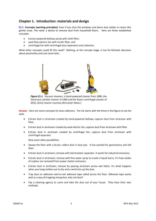
gentle snow. The need: a device to remove dust from household floors. Here are three established
concepts:
human-powered bellows pump with cloth filter;
axial-flow electric fan with muslin filter; and
centrifugal fan with centrifugal dust separation and collection.
What other concepts could fill this need? Nothing, at the concept stage, is too far-fetched; decisions
about practicality and cost come later.
Answer. Here are some concepts for dust collectors. The list starts with the three in the figure to set the
style.
Entrain dust in airstream created by hand-powered bellows; capture dust from airstream with
filter.
Entrain dust in airstream created by axial electric fan; capture dust from airstream with filter.
Entrain dust in airstream created by centrifugal fan; capture dust from airstream with
centrifugal separator.
Now some other possibilities.
Sweep the floor with a brush; collect dust in dust pan. It has worked for generations and still
does.
Entrain dust in airstream; remove with electrostatic separator. It works for industrial emissions.
Entrain dust in airstream; remove with fine water spray to create a liquid slurry. It’s how oxides
of sulphur are removed from power station emissions.
Entrain dust in airstream; remove by passing airstream across wet fabric. It’s what happens
when you hang clothes out to dry and a wind stirs up the dust.
Trap dust on adhesive reel-to-reel adhesive tape rolled across the floor. Adhesive tape works
well as a way of trapping mosquitos; why not dust?
Pay a cleaning agency to come and take the dust out of your house. They have their own
methods.
Figure E1.1. Vacuum cleaners: a hand-powered cleaner from 1880, the
Electrolux cylinder cleaner of 1960 and the Dyson centrifugal cleaner of
2010. (Early cleaner courtesy Worcester News.)
2. MSMD 5e 4 MFA May 2016
E1.2 Function structures. Make a function-structure diagram for the Electrolux cleaner of Figure E1.1.
Answer. The diagram is shown below.
E1.3 Concepts (working principles) for cooling power electronics. Microchips, particularly those for
power electronics, get hot. If they get too hot they cease to function. The need: a scheme for removing
heat from power microchips. One is sketched in Figure E1.2. Its working principle is that of thermal
conduction to fins from which heat is removed by convection.
Four working principles are listed below: thermal conduction, convection by heat transfer to a fluid
medium, evaporation exploiting the latent heat of evaporation of a fluid, and radiation, best achieved with
a surface with high emissivity.
The best solutions may be found by combining two or more of these: conduction coupled with
convection (as in the sketch – an often-used combination). Consider both the case of long term,
continuous-operation heat sinks and the case of short-term, intermittent heat sinks (with pause between
operations for system to return to ambient temperature).
Answer. Concepts for continuous or long-term operation.
Transmission of heat by conduction; removal by natural or fan-assisted convection. (Typical
system in personal computer.)
Transmission of heat by conduction; removal by radiation. (Possible system for operation in
space.)
Transmission of heat by conduction, heat exchanger to pass heat to working fluid; heat removed
from working fluid by convection (a radiator).
Transmission of heat by conduction; heat exchanger to pass heat to working fluid (water, for
instance) drawn from renewable source (a river, for example); working fluid then rejected.
Transmission of heat by conduction, active removal by Peltier (thermoelectric) cooling.
Transmission of heat by conduction, active removal by magnetocaloric (MC) cooling.
Concepts for pulsed or short-term operation.
Conduction of heat into heat sink so massive that the temperature rise is acceptably small.
Conduction of heat to reserve of phase-change material (paraffins, hydrated salts such as
CaCl2.6H2O); heat absorbed by the latent heat of melting.
Figure E1.2. A heat sink
3. MSMD 5e 5 MFA May 2016
Conduction of heat to sacrificial evaporative coating; heat removed by latent heat of
evaporation.
E1.4 Function structures. Make a function-structure diagram for the heat sinks.
Answer. The diagram is shown below.
E1.5 Attaching paper sheets. The need: documents consisting of several pages can become confused if
the pages are loose. Use the internet to explore alternative concepts for attaching a small number of
pages together in a way that still allows them to be read. Record, as far as possible, the materials of the
attachment and the property that provides the attachment force.
Answer.
Systems that rely on elastic stiffness (thus, elastic modulus) to provide the attachment force.
Systems that rely on strength or plasticity to provide the attachment force.
Wood Mild steel Spring steel Spring steel Polypropylene
Mild steel Brass Brass
4. MSMD 5e 6 MFA May 2016
Chapter 2. Engineering materials and properties
These exercises introduce the reader to two useful resources: the data sheets of Appendix A and the
Solutions to Standard Problems of Appendix B. When drawing data from Appendix A use the mean values
of the ranges listed there.
E2.1 Sound velocity. The speed of sound in pyrex (Borosilicate) glass is 5610 m/s. Find the density of this
glass from Appendix A and use it to estimate the modulus E of pyrex.
Answer. The density of Borosilicate glass, from Table A3 of Appendix A, is 2250 kg/m3
. The
longitudinal wave speed (from the text) is
/
E . Thus the modulus of the glass is
GPa
71
Pa
10
x
1
.
7
)
5610
(
x
2250
E 10
2
E2.2 Deflection of beams. A cantilever beam has a length L = 50 mm. It has a
rectangular cross-section width b = 5 mm and a thickness t = 1 mm. It is made of
an aluminum alloy. By how much will the end deflect under an end-load of F = 5
N (roughly that exerted by the weight of 5 apples)? Use data from Appendix A4
for the (mean) value of Young’s modulus of aluminum alloys, the equation for
the elastic deflection of a cantilever from Appendix B3 and for the second moment of a beam from
Appendix B2 to find out.
Answer. The deflection of a cantilever under an end load F is, from Appendix B,
I
E
3
L
F 3
with the second moment of area
12
t
b
I
3
The mean Young’s modulus E for aluminum, from Appendix A3, is 75 GPa. Inserting the data from the
question gives a second moment of area I = 0.42x10
-12
m
4
and an end deflection = 6.7 mm.
E2.3 Deflection of beams. The wings of a glider are each 4m long. The
load-bearing member is the wing spar, a tubular beam running the length
of the wing. The wing spar in this glider has a diameter of 140 mm and a
wall thickness of 6 mm. It is made of an aluminum alloy. In flight the
wing spar is loaded in bending with (we will assume) a uniformly
distributed force per unit length. By how much will the wing-tip deflect in calm flight if the loaded glider
weighs 1000 kg? Use data from Appendix A3 for the (mean) value of Young’s modulus of aluminum alloys,
the equation for the elastic deflection of a cantilever from Appendix B3 and for the second moment of a
beam from Appendix B2 to find out.
Answer. The deflection of a cantilever under a distributed load F is, from Appendix B, Table B3
I
E
8
L
F 3
The second moment of area of a thin-walled tube of diameter R
2 and wall thickness t (Table B2) is
t
R
I 3
Each wing spar carries a distributed load of 500kg (4,910 N). The mean Young’s modulus E for aluminum,
from Appendix A3, is 75 GPa. Inserting the data from the question results in an end deflection = 81 mm.
5. MSMD 5e 7 MFA May 2016
E2.4 Vibration of beams. A cantilever beam with length L = 200 mm, width b
= 12 mm and thickness t = 2 mm weighs 38 grams and has a natural vibration
frequency of f = 42 hertz. What is the modulus of the material of the beam?
You will find equations for natural frequencies of vibration and moments of
area in Appendix B, Tables B12 and B2.
Answer. From Appendix B, the natural frequency of a cantilever beam is
L
m
I
E
56
.
0
f
o
where t
b
mo
is the mass per unit length and
12
bt
I
3
is the second moment of area of the beam. E
and are the modulus and density of the beam. In this example o
m = 0.19 kg/m, and I = 8x10
-12
m
4
.
Inverting the equation for f and solving for the modulus gives E = 214 GPa.
E2.5 Forensic materials science. Exercise E2.4 used a natural vibration frequency to measure the
modulus of a beam. Use the information in E2.4 to calculate the density of the beam, then use this and
the result of the exercise (the modulus of the beam) as a forensic tool. Scan the Modulus values in Table
A3 of Appendix A seeking a match between the calculated modulus and those in the table. What subsets
of materials match the calculated modulus? Of these, which subset also matches the calculated density?
Answer. The density (mass/volume) of the beam of exercise E2.4 is 7920 kg/m
3
. Its modulus, calculated in
exercise E2.4, is 214 GPa. Only one subset of materials – steels – matches both the density and the
modulus. Note that this identification has require only very simple measurement: the dimensions of the
beam, its weight and its vibration frequency.
E2.6 Springs. A spring, wound from stainless steel wire with a wire diameter
= 1mm, has = 20 turns of radius R = 10 mm. How much will it extend
when loaded with a mass M of 1 kg? Assume the shear modulus G of stainless
steel to be 3/8E where E is Young’s modulus, retrieve this from Appendix A3,
and use the expression for the extension of springs from Appendix B6 to find
out.
Answer. The extension of a spring under a force Mg
F = 9.81 N (here is the acceleration due to
gravity) is
4
3
d
G
n
R
F
64
u
Young’s modulus for stainless steel is 200 GPa, so shear modulus
G 76 GPa. Inserting the data gives a
deflection u = 10.4 mm.
d n
u g
6. MSMD 5e 8 MFA May 2016
E2.7 Torsion of tubes. A thick-walled tube has an inner radius i
r = 10 mm and an
outer radius o
r = 15 mm. It is made from polycarbonate, PC. What is the
maximum torque f
T that the tube can carry without the onset of yield? Retrieve
the (mean) yield strength y
of PC from Appendix A3, the expression for the torque at onset of yield from
Appendix B6 and that for the polar moment of a thick walled tube from Appendix B2 to find out.
Answer. The torque at the onset of yield for a thick walled tube is
o
y
f
r
2
K
T
with )
r
r
(
2
K 4
i
4
o
The mean yield strength of y
of PC from Appendix A3 is 65 MPa. Inserting the data from the question
gives a torque at the onset of yield of f
T = 138 N.m.
E2.8 Stress concentrations. A round bar, 20 mm in diameter, has a
shallow circumferential notch with a depth c = 1 mm with a root radius
r = 10 microns. The bar is made of a low carbon steel with a yield
strength of y
= 250 MPa. It is loaded axially with a nominal stress,
nom
(the axial load divided by the un-notched area). At what value of
nom
will yield first commence at the root of the notch? Use the stress
concentration estimate of Appendix B9 to find out.
Answer. The stress concentration caused by notch of depth c and root radius r is
2
/
1
nom
max
r
c
1
with 2
for tension
Yield first starts when y
max
. Inserting the data from the question gives a nominal stress for first yield
of 11.9 MPa. Stress concentrations can be very damaging – in this example, a cyclic stress of only 12
MPa will ultimately initiate a fatigue crack at the notch root.
E2.9 Thermal stress. An acrylic (PMMA) window is clamped in a thick low carbon
steel frame at T = 20 C. The temperature falls toT = -20 C, putting the window
under tension because the thermal expansion coefficient of PMMA is larger than that
of steel. If the window was stress-free at 20C, what stress does it carry at -20 C? Use
the result that the bi-axial stress caused by a bi-axial strain difference
is
1
E
where E is Young’s modulus for PMMA and Poisson’s ratio 33
.
0
. You will find data for expansion
coefficients in Table A6 and for moduli in Table A3, Appendix A. Use mean values.
Answer. The strain difference caused by difference in thermal expansion, , when the temperature
changes by T
is
T
steel
C
Low
PMMA
From Appendix A6,
PMMA
= 117x 10
-6
/C and steel
C
Low
= 12.3 x 10
-6
/C
7. MSMD 5e 9 MFA May 2016
giving
4.2 x 10⁻³
. The modulus of PMMA, from Appendix A3, is
E 3.0 GPa. The equation given in
the question then predicts a tensile stress in the window of = 19 MPa.
E2.10 Unstable cracks. The PMMA window described in Exercise 2.9 has a contained crack of length a
2 =
0.5 mm. If the maximum tensile stress that is anticipated in the window is = 20 MPa, will the crack
propagate? Choose an appropriate equation for crack propagation from Appendix B10 and data for the
fracture toughness c
1
K of PMMA from Appendix A6 to calculate the length of crack that is just unstable
under this tensile stress.
Answer. The crack length is small compared with the width of the window, so the appropriate choice of
equation describing crack instability is
c
1
K
a
C
with 0
.
1
C
Inserting the data we find the length of the shortest crack that is just unstable:
2
c
1
K
2
a
2
= 2.1 mm, using
PMMA
c
1
K 1.15 MPa.m
1/2
Thus the 0.5mm crack will not propagate.
E2.11 Centrifugal stress. A flywheel with a radius R = 200 mm is designed to spin
up to 8000 rpm. It is proposed to make it out of ductile (nodular) cast iron, but the
casting shop can guarantee only that it will have no crack-like flaws greater than a
2 =
2 mm in length. Use the expression for the maximum stress in a spinning disk in
Appendix B7, that for the stress intensity at a small enclosed crack from Appendix
B10 and data for cast iron from Appendix A2 and A4 to establish if the flywheel is
safe. Take Poisson’s ratio for cast iron to be 0.33.
Answer. The maximum tensile stress in a spinning disk is
2
2
max R
8
3
, and c
1
max
1 K
a
K
for a contained crack. Here 60
/
W
2
radians/sec when W is the rotational velocity in rpm. Inserting
the data from the question and the mean values for density = 7200 kg/m3
and c
1
K = 38 MPa.m1/2
from
Appendix A, we find the maximum rotational velocity that will just cause the cracks to propagate is 4350
radians/s, or 41,600 rpm. The flywheel is safe.
E2.12 Blunting cracks. Liberty ships, thousands of which were constructed during
World War II, were welded rather than riveted. Many were mistakenly made from a
steel that became brittle at the temperatures of the Atlantic in winter. They had
square hatches with sharp corners from which a crack could start and propagate
across the deck which, being welded, allowed a continuous path not interrupted by
riveted plates. It is said that alert seamen, observing such a crack to start, would
seize a power drill and drill a hole at the crack tips, effectively blunting it and
reducing the stress concentration. If the crack when the seaman first saw it was 1 m
long, and the largest drill he had was
r
2 25 mm in diameter, what is the stress concentration at the end
of the crack once the hole was drilled? You will find the equation for the stress at a distance r from the tip
of a crack with a length a
2 Appendix B, Table B10.
Answer. A crack concentrates stress locally. This local stress
falls off with distance r from the tip of a
crack as
8. MSMD 5e 10 MFA May 2016
r
2
C
a
where C us a constant, equal to 1 and . By drilling out the material at the crack tip the largest stress is that
evaluated at the surface of the whole, where
r 12.5 mm. Inserting this and the crack length a
2 = 1m
gives a local stress
5
.
4
.
E2.13. Contact forces. A clamp has a hemispherical contact faces of radius R = 10
mm to allow for misorientation. It is used to clamp a heavy lead archaeological
treasure for X-ray examination. How much clamping force, F , can be applied
without damage (meaning plastic deformation) to the treasured object? You will find
the both the modulus E and yield strength y
of lead alloys in Appendix A, Table A3
(use mean values), and the equation for force required to trigger plastic deformation
beneath a spherical indenter in Appendix B, Table B8.
Answer. From Table A3, the yield strength of lead alloys is 11 MPa and the modulus is 14 GPa. The force to
cause yielding below a spherical indenter, from Table B8, is
y
2
s 3
a
F
Immediately before yielding starts, the contact is elastic and a is the radius of the contact-patch, a , is
3
/
1
E
R
F
7
.
0
a
Combining these equations and solving for the clamping force F gives
3
y
2
E
R
126
F
Entering values for the parameters gives a permissible clamping force of 0.085 N. This is an impossibly low
clamping force so clamping the object in this way is impractical. A softer clamping system, distributing load
over a much larger area, is needed.
E2.14 Estimating thermal properties. You wish to measure, approximately, the thermal conductivity of
polyethylene (PE). To do so you block one end of a PE pipe with a wall thickness of x = 3 mm and
diameter of 30 mm and fill it with boiling water while clutching the outside with your other hand. You note
that the outer surface of the pipe first becomes appreciably hot at a time
t 18 seconds after filling the
inside with water. Use this information, plus data for specific heat p
C and density of PE from Appendix
A, Tables A2 and A5, to estimate for PE. How does your result compare with the listed value in Table A7?
Answer. The distance x that heat diffuses in a time t is approximately
t
a
2
x with
p
C
a
9. MSMD 5e 11 MFA May 2016
(a is the thermal diffusivity). Inserting the data from the question and the mean values = 950 kg/m3
and p
C = 1850 J/kg/K from the Appendix, we find
0.44 W/m.K. The result given in Appendix A6 for
the thermal conductivity of PE is 0.40 – 0.44 W/m.K.
E2.15 Heat exchangers. A power transistor with an area of A of 1 mm2
dissipates 10 watts. It is attached
to a heat sink 2 mm thick, effectively cooled to 30 C on the back face by forced air flow. If the heat sink is
made of aluminium nitride, how hot will the microchip be at steady state? You will find equations of heat
flow in Appendix B, Table B15, and the thermal properties of aluminium nitride in Appendix A, Tables A5 an
A6.
Answer. The thermal conductivity of aluminium nitride, from Table A6, is 170 W/m.K The basic equation of
steady-state heat flux J (J/m2
.sec) (Table B15), is
dx
dT
J
where is the thermal conductivity and dT/dx is the temperature gradient. The heat flow, q , away from
the transistor is
T
10
x
5
.
8
10
x
2
T
x
170
x
10
x
1
dx
dT
A
J
A
q 2
3
6
watts
Equating this to the dissipated power, 10 watts, and solving for T
gives
T
118 o
C
Thus the temperature of the transistor is 148 C.
E2.16 Choosing dielectrics. The capacitance C of a condenser with two plates each of area A separated by
a dielectric of thickness t is
t
A
C o
r
where o
is the permittivity of free space and r
is the dielectric constant of the material between the
plates. Select a dielectric by scanning data in Appendix A, Tables A7 and Table A8, first to maximize C and
second to minimize it, for a given A and t .
Answer. (a) Capacitance is maximized by selecting materials with high r
. Appendix A shows that most
polymers and ceramics have dielectric constants in the range 2 – 10, the ferroelectric ceramics barium
titanate, lead zirconium titanate (PZT) and lead lanthanum zirconium titanate (PLZT) all have dielectric
constants greater than 1000.
(b) Capacitance is minimized by materials with low r
: the non-polar polymers polyethylene,
polypropylene and teflon (PTFE) are the lowest among solid materials. Polymer foams have low dielectric
constants because they are mainly air (dielectric constant 1)
10. MSMD 5e 12 MFA May 2016
E2.17 Piezoelectric actuators. Piezoelectric materials respond to an electric field by change of shape. The
strain induced by a field E is
E
d33
where 33
d is the piezoelectric charge coefficient, listed in Table A8. Its units are pm/V. A sample of soft
PZT (lead zirconium titanate) is exposed to a field of 10 MV/m. How large is the resulting strain? You will
find the piezoelectric charge coefficient for soft PZT in Table A8. Use a mean value.
Answer. The piezoelectric charge coefficient 33
d for soft PZT is 675 x 10-12
m/V. Thus a field of 10 x 106
V/m will induce a strain of
6.75 x 10-3
= 0.675%.
E2.18 Pyroelectric temperature sensing. Remote, non-contact, temperature sensing is possible lby
focussing radiation from the source onto a pyroelectric material, using the charge that appears on its
surface as a measure of temperature. A sensor is required to measure temperature in the range 100 – 200
C. To work in this range the material must have a ferro-electric Curie temperature greater than 200 C,
since otherwise it ceases to be pyroelectric in the sensing range. The signal is maximized by selecting a
material with the largest possible pyroelectric coefficient. Use the data for pyroelectrics in Appendix A,
Section A8, to make a selection.
Answer. Lithium niobate has the largest pyroelectric coefficient of those listed in the table but its ferro-
electric Curie temperature is too low to allow its use in the range 100 – 200 C. Lithium tantalite best meets
the criteria for the sensor described in the question.
E2.19 Magnetostrictive actuation. A magnetostrictive actuator has and active core of length L = 20 mm. It
is made of Terfenol D, a giant magnetostrictive alloy of terbium, dysprosium and iron. If a field sufficiently
large to saturate the core is applied, by how much will the core change in length? Use the mean value of
the data for Terfenol D listed in Appendix A, Section A9, to find out.
Answer. The mean saturation magnetostrictive strain sat
for Terfenol D, from Appendix A, is 1,700 x 10-6
.
Thus the core will change in length by
L
sat
= 1,700 x 10
-6
x 20 x 10
-3
= 3.4 x 10
-5
m = 34 m
E2.20 Material price. It is proposed to replace the cast iron casing of a power tool with one with precisely
the same dimension molded from nylon. Will the material cost of the nylon casing be greater or less than
that made of cast iron? Use data from Appendix A3 and A11 to find out.
Answer. If the dimensions of the cast iron and nylon cases are the same, the volume of material required
to make them are equal. Thus the cheaper option is the one with the lower material cost per unit volume
v
C , where
m
v C
C
and is the material density and m
C the material cost per kg. Data from Appendix A3 and A11 are
assembled below, using the means of the ranges.
Density
kg/m3
Price
$/kg
Cost per unit vol
$/m3
Cast iron 7150 0.63 4500
Nylon 1130 3.45 3900
Surprisingly, the nylon casing has a lower material cost than that made of cast iron.
11. MSMD 5e 13 MFA May 2016
E2.21. Carbon footprint. Plastics are sometimes portrayed as environmentally poor because most are
synthesize from oil or natural gas, implying a larger embodied energy and carbon footprint than other
materials. Is this an accurate portrait? Use the data from Appendix A, Table A10 and A2 to compare the
carbon footprint of three of the materials most widely used in household products: polypropylene,
aluminium and carbon steel. Use mean values of the values in the tables.
Answer. Carbon steel has the lowest carbon footprint per unit weight, polypropylene the next lowest. If
ranked instead by carbon footprint per unit volume, polypropylene has by far the lowest value. Any serious
comparison of this type needs a more detailed examination: materials are used in products because they
perform a function. If these three materials are candidates, the best choice is that with the lowest carbon
footprint per unit of function. We explore ways to do this in later chapters of this book.
Density
kg/m3
Carbon footprint
kg/kg
Carbon footprint
kg/m3
Polypropylene 900 3.15 2840
Aluminum 2700 12.5 33,800
Carbon steel 7850 1.8 14,100
12. MSMD 5e 14 MFA May 2016
Chapter 3. Material property charts
The 32 exercises in this section involve the simple use of the charts of Chapter 3 to find materials with give
property profiles. They are answered by placing selection lines on the appropriate chart and reading off the
materials that lie on the appropriate side of the lines. It is a good idea to present the results as a table. All
can be solved by using the printed charts, which you are free to copy for your personal use.
If the CES Edu Materials Selection software is available, the same exercises can be solved by its use. This
involves first creating the chart, then applying the appropriate box or line selections. The results, at Level 2,
are the same as those read from the hard copy charts (most of which were made using the Level 2
database). The software allows more detailed charts using the Level 3 database.
E3.1 Use Figure 3.3 to identify one metal and one polymer with a longitudinal wave speed close to 1000
m/s.
Answer. Lead and polypropylene both lie close to the contour of longitudinal wave speed of 1000 m/s.
E3.2 A component is at present made from a brass, a copper alloy. Use the Young’s modulus – Density
(
E ) chart of Figure 3.3 to suggest three other metals that, in the same shape, would be stiffer.
“Stiffer” means a higher value of Young’s modulus.
Answer. Metals that are stiffer than brass are listed in the table.
Material Comment
Steels The cheapest stiff, strong structural metal, widely used.
Nickel alloys More expensive than steel
Tungsten alloys Refractory (high-melting) and relatively expensive
E3.3 Use the Young’s modulus – Density (
E ) chart of Figure 3.3 to identify materials with both a
modulus E > 50 GPa and a density < 2000 kg/m3
.
Answer. There are only two materials on the chart with modulus E > 50 GPa and density < 2000 kg/m3.
Material Comment
Magnesium alloys Magnesium is the lightest of all common structural metals – only
beryllium is lighter, but it is very expensive and its oxide is toxic.
CFRP – carbon-fiber
reinforced plastic
CFRP is both lighter and stiffer than magnesium. That is one
reason it is used for competition cars and bikes.
13. MSMD 5e 15 MFA May 2016
E3.4 Use the Young’s Modulus-Density (
E ) chart of Figure 3.3 to find (a) metals that are stiffer and
less dense than steels and (b) materials (not just metals) that are both stiffer and less dense than
steel.
Answer. (a) No metals in Figure 3.3 are both stiffer and less dense than steel, though nickel alloys come
close. (b) Several ceramics qualify: Boron carbide, B4C, silicon carbide, SiC, silicon nitride Si3N4,
alumina Al203 and (inevitably) diamond.
Material Comment
Alumina Al203 Alumina is the most widely used of all technical ceramics
(spark plugs, circuit boards…) All ceramics are brittle – they
have low values of fracture toughness c
1
K and toughness c
1
G .
They are, however, exceedingly hard, so are used as cutting
tools.
Silicon nitride Si3N4
Boron carbide, B4C
Silicon carbide, SiC
Diamond
E3.5 Use the (
E ) chart of Figure 3.3 to identify metals with both E > 100 GPa and
/
E > 0.02
GPa/(kg/m3).
Answer. The chart shows the selection. The metals that lie in the search area are listed in the table.
Material Comment
Steels Cheap, widely used. Stiff structural material.
Nickel alloys More expensive than steel
Titanium alloys Titanium alloys are very expensive.
E = 100 GPa
E/ = 0.02
GPa/(kg/m
3
)
Search area
14. MSMD 5e 16 MFA May 2016
E3.6 . Use the
/
E chart of Figure 3.3 to identify materials with both E > 100 GPa and
/
E 3
/
1
>
0.003 (GPa)
1/3
/(kg/m3). Remember that, on taking logs, the index
/
E
M 3
/
1
becomes
)
M
log(
3
)
log(
3
)
E
log(
and that this plots as a line of slope 3 on the chart, passing through the point E = 27 when =
1000 in the units on the chart.
Answer. The chart shows the selection. The materials that lie in the search area are listed in the table.
No metals survive.
Material Comment
CFRP Carbon-fiber composites excel in stiffness at low weight.
Boron carbide, B4C Boron carbide is exceptionally stiff, hard and light; it is used
for body armour.
E3.7 Use the
E chart of Figure 3.3 to establish whether woods have a higher specific stiffness
/
E than epoxies.
Answer. Parallel to the grain, woods have much higher specific stiffness than epoxies. Perpendicular to
the grain, woods have about the same value as epoxies.
Material E/ (GPa/(kg/m
3
) x 10
3
Woods parallel to the grain
Woods transverse to the grain
8 - 29
0.7 – 4.0
Epoxies 1.8 – 2.5
Slope 3
E
1/3
/ = 0.003 (GPa
1/3
)/(kg/m
3
)
E = 100 GPa
Search area
15. MSMD 5e 17 MFA May 2016
E3.8 Do titanium alloys have a higher or lower specific strength (strength/density,
/
f ) than the
best steels? This is important when you want strength at low weight (landing gear of aircraft,
mountain bikes). Use the
/
f chart of Figure 3.4 to decide.
Answer. The guide line for specific strength,
/
f , on the strength – density chart of Figure 3.4, if
drawn through the middle of the bubble for titanium alloys, passes above the elongated bubble for
steels. Thus titanium alloys have a higher specific strength than steels steel, even though the best
steels are as strong.
Material
/
f (MPa/(kg/m
3
)) x 10
3
Titanium alloys 54 - 270
Steels 25 - 170
Search area