
Recommended
More Related Content
Similar to PON-testing-app-note.pdf
Similar to PON-testing-app-note.pdf (20)
More from ssuser818de4
Recently uploaded
Recently uploaded (20)
PON-testing-app-note.pdf
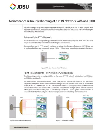
- 1. Application Note WEBSITE: www.jdsu.com/test CO ONT 1 Coaxial cable Final customer 1 ONT 1 ONT 1 ONT 1 Coaxial cable Final customer 1 ONT 2 Final customer 2 Coaxial cable ONT 2 ONT 2 ONT 2 Final customer 2 Coaxial cable ONT 3 Coaxial cable Final customer 3 ONT 3 ONT 3 ONT 3 Coaxial cable Final customer 3 Splitter OLT ONT or ONU OLT ONT or ONU ONT 1 Coaxial cable Final customer 1 ONT 1 ONT 1 ONT 1 Coaxial cable Final customer 1 ONT 2 Final customer 2 Coaxial cable ONT 2 ONT 2 ONT 2 Final customer 2 Coaxial cable ONT 3 Coaxial cable Final customer 3 ONT 3 ONT 3 ONT 3 Coaxial cable Final customer 3 Splitter CO Maintenance & Troubleshooting of a PON Network with an OTDR Point-to-Point FTTx Network When a failure occurs on a point-to-point FTTx network, the network completely shuts down. It is then easytodisconnectthefiberwithoutfurtheraffectingthecustomerissue. To troubleshoot and fix FTTx network problems, an optical time domain reflectometry (OTDR) test can beperformedwithanytestwavelength,suchas1310or1550nmasthetransmissionsignalsareshutdown. ONT 1 Coaxial cable Final customer 1 ONT 1 ONT 1 ONT 1 Coaxial cable Final customer 1 Switch or OLT ONT or DSLAM CO Figure1.FTTxCase=Point-to-PointFTTHNetwork Figure2.SimplePONNetworkTopology Figure3.CascadedPONTopology Point-to-Multipoint FTTH Network (PON) Topology Troubleshooting a point-to-multipoint fiber-to-the-home (FTTH) network (also defined as a PON net- work)differssignificantly. The International Telecommunications Union (ITU-T) and Institute of Electrical and Electronic Engineers (IEEE) have created several standards for optical access systems based on PON architecture (G.982, G.983 or G.984 for ITU and 802.3ah or 802.3av for IEEE). As Figure 2 shows, a PON network consists of one optical line terminal (OLT) connected via a splitter to multiple optical network terminals (ONTs) (one for each subscriber, up to 64 subscribers). Sometimes, a second splitter can be connected in cascadetothefirstsplitter(asFigure3shows)todispatchservicestobuildingsorresidentialareas. Troubleshooting a faulty passive optical point-to-multipoint network (PON) can be more complex than a point-to-point network. This application note looks at the use of non-intrusive or active fiber testing for troubleshootingPONnetworks.
- 2. Application Note: Maintenance & Troubleshooting of a PON Network with an OTDR 2 Using the network monitoring system at the Network Operation Center (NOC), operators can easily determine which subscribers are affected. They can also identify possible fault elements such as how many customersareaffectedandwhetherthePONiscascaded. Thecasesbelowdescribeeachpossiblescenario: PONCase1:SimplePON-OnlyOneCustomerisAffected Whenonlyonesubscribercannotreceiveservice,threepotentialfaultsareprobable,seeFigure4: ‒ Faultinthedistributionfiberbetweenthecustomerandtheclosestsplitter ‒ FaultintheONTequipment ‒ Faultinthecustomer’shomewiring Figure4.PONCase1—PossibleFaultsWhenOnlyOneSubscriberisAffected PONCase2:CascadedPONandallAffectedCustomersareConnectedtotheSameSplitter When all customers connected to the same splitter cannot receive service, but others connected to the sameOLTcan,thecausemaybebecauseofoneofthefollowing(seeFigure5): ‒ Faultatthelastsplitter ‒ Faultinthefiberlinkbetweenthecascadedsplitters Figure5.PONCase2—CascadedPONwithAffectedSubscribersConnectedtoLastSplitter ONT 1 Coaxial cable Final customer 1 ONT 1 ONT 1 ONT 1 Coaxial cable Final customer 1 ONT 2 Final customer 2 Coaxial cable ONT 2 ONT 2 ONT 2 Final customer 2 Coaxial cable ONT 3 Coaxial cable Final customer 3 ONT 3 ONT 3 ONT 3 Coaxial cable Final customer 3 Case 1.A - Simple PON - Only one customer affected Splitter 1 2 3 OLT ONT or ONU ONT 1 Coaxial cable Final customer 1 ONT 1 ONT 1 ONT 1 Coaxial cable Final customer 1 ONT 2 Final customer 2 Coaxial cable ONT 2 ONT 2 ONT 2 Final customer 2 Coaxial cable ONT 3 Coaxial cable Final customer 3 ONT 3 ONT 3 ONT 3 Coaxial cable Final customer 3 First splitter Last splitter 1 2 3 OLT ONT or ONU ONT 1 Coaxial cable Final customer 1 ONT 1 ONT 1 ONT 1 Coaxial cable Final customer 1 ONT 2 Final customer 2 Coaxial cable ONT 2 ONT 2 ONT 2 Final customer 2 Coaxial cable ONT 3 Coaxial cable Final customer 3 ONT 3 ONT 3 ONT 3 Coaxial cable Final customer 3 First splitter Case 2 Cascaded PON Last splitter 1 2 OLT ONT or ONU
- 3. Application Note: Maintenance & Troubleshooting of a PON Network with an OTDR 3 PONCase3:AllCustomersareAffected(attheOLTlevel) Whether or not the PON is cascaded, all customers dependant on the same OLT may be affected. If all cus- tomersareaffected,thecausemaybefromofthefollowing: ‒ FaultinthesplitterclosesttotheOLT ‒ Faultinthefeederfiber/cableofthefibernetwork ‒ FaultintheOLTequipment Figure6.PONCase3—AllSubscribersareAffected(AllConnectedtotheFirstSplitter) Other Variable: Splices or Connectors at Strategic Places If connectors are available at the splitters, terminals, or drops, isolating part of the faulty network easier. Inspecting connectors and taking OTDR measurements using 1310/1550 nm wavelengths are often per- formedonnetworksectionsthatareoutofservice. In-service testing (test on a network carrying traffic) is needed mostly when the entire network is spliced andwhensomebutnotallcustomersareaffected. Constraints of In-service Testing Measurements InordertotroubleshootPONnetworksinservice,twodedicatedtoolsareavailable: -PONpowermeter -In-service1625or1650nmOTDR Traffic wavelengths are typically 1310/1490 or 1310/1490/1550 nm. A PON power meter is normally employed to verify that the signal is transmitted correctly to and from the ONT. A PON meter measures the power levels of all the signals and can then discriminate whether the issue comes from the customer’s ONTorfromthenetwork. The use of a classical OTDR with 1310 or 1550 nm test wavelengths would interfere with the traffic signals and disturb the traffic. At the same time, the traffic signals could also disturb the receiver of the OTDR, making it difficult to interpret OTDR traces. Because of these mutual disturbances, classical OTDRs cannot be used, and specific in-service OTDRs are required (see section on Specific In-service Portable OTDR Device). ONT 1 Coaxial cable Final customer 1 ONT 1 ONT 1 ONT 1 Coaxial cable Final customer 1 ONT 2 Final customer 2 Coaxial cable ONT 2 ONT 2 ONT 2 Final customer 2 Coaxial cable ONT 3 Coaxial cable Final customer 3 ONT 3 ONT 3 ONT 3 Coaxial cable Final customer 3 First splitter 1 2 3 OLT ONT or ONU
- 4. Application Note: Maintenance & Troubleshooting of a PON Network with an OTDR 4 Recommended Steps for Locating Faults Despite the fact companies with diverse fiber networks have their own methods and procedures, most of themoptimizetheirfaultlocationprocesstoreducethenumberoftruckrolls. TheschematicinFigure7offersacompleteviewof: ‒ Allofthepossiblefaultlocations,dependingonhowmanycustomersareaffected ‒ ThebestlocationtoshootanOTDRwhileminimizingtruckrolls ‒ Whetherornotaspecificin-serviceOTDRdeviceshouldbeused Figure7.SchematicSummary - The OLT - The distribution fiber - The ONT - The customer home wiring PONNetwork (Multi-Point FTTHnetwork - The distribution fiber between the customer &the closest splitter - The ONT - The customer home wiring See Figure 4 More than one Shoot an OTDR from the last splitter towards the ONT In service measurement Yes Shoot an OTDR from the ONTup to the closest splitter No Possible faultyelements Shoot an OTDR from the OLT towardsthe ONT - The last splitter - The fiber link between the cascaded splitters See Figure 5 Are connectors availabe at the last splitter? No Shoot an OTDR from the last splitter towards the fist splitter Yes - The OLTitself - The feeder part of the fiber network - The first splitter See Figure 6 What type of FFTx Network is it? How many customersare affected? Are affected customers connected to the same first splitter? Shoot an OTDR from the OLT towardsthe first splitter Which scenario? Second step analysis Shoot an OTDR from the ONT towardsthe closest splitter One only(whethercascaded splitterornot) PON Case 1 PON Case 2 No=> cascaded splitter Yes(wethercascaded splittersornot) PON Case 3 Test 1 Test 2 Test 3 Test 4 Test 5 Test 6 Out of service measurement Point toPoint FTTx Network Case FTTx Are connectors availabe at the last splitter? (Assuming problem could not be solved by phone)
- 5. Application Note: Maintenance & Troubleshooting of a PON Network with an OTDR 5 Specific In-service Portable OTDR Device The in-service OTDR was designed specifically for testing live fiber networks. This dedicated device uses an out-of band wavelength (test wavelength far away from traffic wavelength) to enable OTDR testing withoutdisturbingeitherthenetworktransmittersorthereceivers. JDSU first developed this particular OTDR a few years ago, allowing dark fiber providers to perform in-service monitoring on metropolitan and long-distance networks. In this case, a wavelength dense mul- tiplexer(WDM)isrequiredtoconnecttheOTDRtothenetworkitselfwhilethetrafficremainsactive. In the case of a PON network, this WDM is no longer needed, except for monitoring purposes (using a remote fiber test system). The PON network is a point-to-multipoint configuration and the troubleshoot- ing test is performed directly from an accessible element (ONT or splitter). The operator can disconnect theelementbecauseserviceisalreadyoffdownstreamtowardthecustomer. First, the in-service OTDR must not disturb the other customers while shooting the OTDR test wave- length upstream toward the OLT, which is most likely the case, as OLTs reject signals above 1625 nm, basedonITU-Trecommendations. Second, the traffic signals that the OTDR receives will be rejected to obtain accurate OTDR traces. The specific long-pass filter used to protect the OTDR diode can be added either via a jumper between the OTDRandthenetworkorbuiltintotheOTDR. Most equipment providers enable the use of the 1625 nm wavelength for safe testing. Some countries, such as Japan, are nevertheless pushing the 1650 nm wavelength as reflected in the ITU-T L.41 recommen- dation, which provides maintenance wavelengths on fiber-carrying signals. The 1650 nm wavelength is preferred based on the design of the filters and also because it is further away from the traffic signals (cur- rentandfuturePONtechnologies). Figure8.OTDRInsertionforIn-serviceMonitoring Figure9.OTDRInsertionforFTTHTroubleshootingataCustomerLocation(ONTisdisconnected) Tx OTDR WDM Link #1 SP Filter LP Filter Multiplexer OTDR Filter ONT 2 Final customer 2 Coaxial cable OLT OTDR with built-in LP filter ONT disconneted Signals ……………….. Live traffic ……………………………………… ONT 3 Coaxial cable Final customer 2 ONT 3 ONT 3 ONT 3 Coaxial cable Final customer 2 ……………….. Live traffic …………………… ………………..NO TRAFFIC …………………… Test wavelength
- 6. Application Note: Maintenance & Troubleshooting of a PON Network with an OTDR 6 Making the Right Testing Decisions To optimize maintenance costs and time, it is essential to select the right OTDR tool, the correct pulse width, and the best location to start troubleshooting. OTDR configuration should be set according to the equipmentbeingqualifiedandthedistancetocover. Consider each case from the scenarios presented in Figure 7. To avoid complexity, this document only analyzesthecaseswhere connectorsareonlyavailableattheONT/OLTs. Case1:TroubleshootingoftheDistributionFiber SimplePON—Onlyonesubscriberaffected. Considerthatnoconnectorsareavailableatthesplitter(seeFigure7,Test3) Case Test OTDR WhatMust Comment PulseWidth SpecificOTDR Location Direction beSeen toUse Case 1 Customer’s Upstream Distribution Testing through Short pulse In-service OTDR One Home fiber up to the splitter 3 to 30 ns customer Disconnect the closest splitter is not required, down the ONT as the issue is only on the distribution fiber side. Figure10.OTDRisShotUpstreamandTraceonlyMattersuptotheSplitter Test the distribution Fiber from Customer 2 up to the closest splitter No need to test beyond the splitter The OTDR trace must clearly show all events until the closest splitter Test direction (upstream)
- 7. Application Note: Maintenance & Troubleshooting of a PON Network with an OTDR 7 Test the distribution Fiber from Customer 2 up to the very first splitter Last splitter First splitter Test direction (upstream) Need to test beyond the closest splitter up to the first splitter Case2: TroubleshootingoftheDistributionFiberandtheFiberbetweentheTwoSplittersincase ofaCascadedNetwork Acascadednetworkwith1x4or1x8splittersisoftenfoundinEurope. Information received at the network operations center (NOC) says that all customers linked to the second splitter are down. Let’s consider the case where no connectors are available at the splitter (see Figure 7, Test5). Case Test OTDR WhatMust Comment PulseWidth SpecificOTDR Location Direction beSeen toUse Case 2 Customer’s Upstream Distribution fiber Testing through Medium pulse In-service OTDR All customers home and fiber between the closest splitter 100 to 300 ns - Short dead zone are down Disconnect the two splitters is required after the the ONT second splitter This case requires viewing the signal after the splitter. The OTDR used must be optimized for this applica- tionandhavetheshortestpossibledeadzoneasthesplittertypicallyprovides7to10dBloss. Figure11.OTDRisShotUpstreamandTraceshouldDisplaytheTrafficthroughtheLastSplitteruptotheFirstOne
- 8. Application Note: Maintenance & Troubleshooting of a PON Network with an OTDR 8 Case3:TroubleshootingoftheFeeder Whether it is a non-cascaded network, which is typical in the USA, or a cascaded network, which is typical inEuropeandAsiaPacific,informationreceivedattheNOCshowsthatallcustomersaredown. As the problem likely comes from the feeder side, the most common way to test the faulty network is to shootanOTDRdownstreamfromtheOLT(seeFigure7,Test6). Case Test OTDR WhatMust Comment PulseWidth SpecificOTDR Location Direction beSeen toUse Case 3 OLT Downstream Feeder Testing through Short pulse Unnecessary All the splitter is 3 to 30 ns customers unnecessary are down Figure12.OTDRisShotDownstreamandTraceshouldDisplaytheTrafficDowntotheFirstSplitter Test the feeder up to the splitter No need to test beyond the first splitter The OTDR trace must clearly show all events down to the first splitter Test direction (downstream)
- 9. Application Note: Maintenance & Troubleshooting of a PON Network with an OTDR 9 TroubleshootingtheDistributionFiberand/ortheFiberbetweenSplitterswithAlternativeOTDRTesting fromtheOLT OTDR testing directly from the OLT is certainly the preferred choice when a faulty feeder is suspected (Case 3), but this method is not recommended in the other cases. JDSU OTDR instruments can indeed test through splitters and provide accurate traces. Nevertheless, complete analysis of the resulting trace requireslinkingthattracetotheexact(preciselydocumented)networktopology. Figure13.OTDRisShotDownstreamandTraceDisplaysManyEventsthatareDifficulttoIdentifywithoutExactNetworkTopology(and correspondingdistances) Total Trace from the OLT Shoot downstream from the feeder All splitters & ONTs can be seen The OTDR trace shows all events, including the first splitter 1*8, some end of fibers, the second splitter 1*4… Test direction (downstream)
- 10. Application Note: Maintenance & Troubleshooting of a PON Network with an OTDR 10 Complete PON Test Tools This application note focuses primarily on the maintenance and troubleshooting of a PON network using an OTDR. Nevertheless, other tools can be used during the installation and maintenance/trouble- shootingstages: InstallationPhase Thefollowingequipmentmaybeused: ‒ Losstestset(providesinsertionlossandORL,eitherunidirectionallyorbidirectionally) ‒ OTDR For this phase, JDSU recommends the SmartClass™ Family and/or the T-BERD®/MTS-4000 or -6000 to optimizethisprocess. Figure14.Recommendedtools:aSmartClassFamilyopticalhandheldoraT-BERD/MTS-4000orT-BERD/MTS-6000equippedwithan OTDRmodule Turn-upPhase Thefollowingequipmentsshouldbeusedinconjunction: ‒ APONpowermeter(1310/1490,1490/1550,or1310/1490/1550nm) ‒ IPtesters(voice,data,video)andcoaxialtesters For this phase, JDSU recommends our SmartClass Family, in particular the PON-dedicated OLP-57, the T-BERD/MTS-4000andtheHST-3000tooptimizethisprocess. Figure15.Recommendedtools:anHST-3000,aSmartClassFamilyOLP-57andaT-BERD/MTS-4000equippedwithaPONpowermeter
- 11. Application Note: Maintenance & Troubleshooting of a PON Network with an OTDR 11 MaintenanceandTroubleshootingPhase Thefollowingequipmentsshouldbeusedinconjunction: ‒ APONpowermeter(1310/1490,1490/1550,or1310/1490/1550nm) ‒ AlosstestsetoranOTDR ‒ IPtesters(voice,data,video)andcoaxialtesters Forthisphase,JDSUrecommendsoncemorethematerialdescribedabove. Figure16.TheDedicatedFTTxT-BERD/MTS-4000PlatformcanbeEquippedwithaPON,anOTDR,andTriple-Play/WiFiTesting *Refer to the JDSUTriple-Playbookformoreinformation,whichisavailableondemandat: www.jdsu.com/products/communications-test-measurement/products/details/triple-play-service-deployment.html
- 12. Application Note: Maintenance & Troubleshooting of a PON Network with an OTDR 12 Product specifications and descriptions in this document subject to change without notice. © 2010 JDS Uniphase Corporation 30162937 000 0110 PONOTDR.AN.FOP.TM.AE January 2010 Test & Measurement Regional Sales NORTH AMERICA TEL: 1 866 228 3762 FAX: +1 301 353 9216 LATIN AMERICA TEL: +1 954 688 5660 FAX: +1 954 345 4668 ASIA PACIFIC TEL: +852 2892 0990 FAX: +852 2892 0770 EMEA TEL: +49 7121 86 2222 FAX: +49 7121 86 1222 WEBSITE: www.jdsu.com/test