1. Winkler, Basics of Electricity/Electronics Workshop, p.1
Basics of Electricity/Electronics
http://www.cla.purdue.edu/vpa/etb/
Fabian Winkler
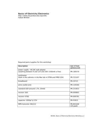
Required parts/supplies for this workshop:
Description Get it from
Jameco.com
power supply – AC/DC wall adapter
(anything between 9 and 12V and 200-1500mA is fine) PN 189579
multimeter
(look in the cabinets in the Mac lab in STEW and FPRD 204) PN 355207
breadboard PN 20723
wires (solid core) PN 126360
standard LED (around 1.7V, 20mA) PN 253833
resistor 1kΩ PN 690865
resistor 470Ω PN 690785
capacitor 1000µF @ 25V PN 93833
NPN transistor 2N2222 PN 803268
(10 pack)
2. Winkler, Basics of Electricity/Electronics Workshop, p.2
Basics of Electricity/Electronics
What is electricity?
To answer this question we will watch an instructional film: “Principles of Electricity”,
1945, General Electric Research Laboratories. Scientific Advisors: Dr. Saul Dushman;
Dr. Roman Smoluchowski; Dr. David Harker (from: www.archive.org)
Please try to find answers to the following questions while watching the film:
• What are electrons?
• What makes them move from atom to atom?
• What is Voltage?
• What is Current?
• What is Resistance?
• How do these three concepts relate to each other?
• What are conductors, what are insulators?
Electricity Basics - some answers to the questions above:
3. Winkler, Basics of Electricity/Electronics Workshop, p.3
For the following concepts please also consult the course book “Physical
Computing” (O’Sullivan/Igoe) chapter 1 (pp. 2-8) for a more detailed description
of the basics of electricity.
Current (I)
Current is the quantity of electrons passing a given point. The unit of current is the
Ampere. One Ampere is 6,280,000,000,000,000,000 electrons passing a point in one
second. Electrical current flows from a region of high charge or potential to a region
of low potential. To make confusion worse there exist two notions about the
direction in which current flows: Conventional Current assumes that current flows out
of the positive terminal, through the circuit and into the negative terminal of the
source. This was the convention chosen during the discovery of electricity. They were
wrong! Electron Flow is what actually happens and electrons flow out of the negative
terminal, through the circuit and into the positive terminal of the source. However,
the concept of Conventional Current is still applied to almost all the circuit
schematics today, so we will use it extensively in this class.
Voltage (V or E)
Voltage is electrical pressure or force. Voltage is sometimes referred to as Potential.
Voltage Drop is the difference in Voltage between the two ends of a conductor
through which current is flowing.
Power (P)
The work performed by an electrical current is called Power. The unit of Power is the
Watt.
Resistance (R)
Conductors are not perfect. They resist to some degree the flow of current. The unit
of resistance is the Ohm.
Load
The part of the circuit which performs work (e.g. a motor, a light bulb or a LED, etc.)
is called Load.
Ohm's Law
A set of rules that show the relationships among Current, Voltage, Power and
Resistance. Given any two of the above, one is able to calculate the other two using
the following formulas:
E = I x R
I = E / R
R = E / I
P = E x I
Direct Current Electricity
An electrical current can flow in either of two directions through a conductor. If it
flows in only one direction whether steadily or in pulses, it is called direct current
(DC). Almost all the projects in class will be powered by DC electricity. In order to be
able to work with DC we need to convert the alternating current (AC) from the outlets
into a direct current, which we use to power our circuits. A wall adapter transforms
AC into DC, the wall adapter in our lab kit transforms 120 VAC into 9/12VDC. The
maximum current it can provide is 1000mA (1A). The wall adapter has two wires that
4. Winkler, Basics of Electricity/Electronics Workshop, p.4
go to our circuits - one for positive power supply and one for negative (ground, or
GND).
Please also read chapters 2 and 3 in our course book “Physical Computing” (pp.
9 -48) in addition to following the following examples, descriptions and
experiments:
We take our power supply and cut off its plug - we want to replace it with a header
that fits better in our prototyping boards. Solder the header to the power supply’s
two wires as illustrated in the following picture. To prevent the solder joints from
breaking put a blob of hot glue around them:
Since direct current only flows in one direction, we have to be able to easily
determine the positive and negative side of the power supply. Remember that we
assume the conventional current flow from positive to negative when we work with
circuits! By convention, positive is always marked with red and negative is always
marked with black or blue.
A multimeter is a useful tool that helps us finding the positive and negative side of
the power supply. On the multimeter’s rotary selection knob we see different sections
for measuring voltage (volt-meter), current (am-meter) and resistance (ohm-meter),
hence the name: multimeter.
The multimeter has two test probes - one red (for positive) and one black (for
negative). We know that our power supply has an output of 9/12VDC, so we first
need to set the multimeter’s scale to Volts (DC not AC) and then to a maximum
amplitude of 20V. If we put the multimeter’s positive probe on the power supply’s
positive side and the negative probe on the negative side, we should get a read-out
of roughly 9/12VDC on the multimeter’s display.
5. Winkler, Basics of Electricity/Electronics Workshop, p.5
Take a red marker and mark the side of the power supply’s header connected to the
multimeter’s red probe red - this is your positive power supply. Or mark the other
side black or red. This is very important. You can blow a circuit easily by applying the
voltage in the wrong direction.
Just in case the read-out shows -9/12VDC (negative!) then we have placed the
probes in the exact opposite way. Switch them and you should get a positive
9/12VDC reading. Finally, also mark the sides of the power supply’s header properly!
Breadboard
Breadboards are useful solderless prototyping boards that allow you to test out
circuits quickly. In general it is a good idea to build every circuit on a breadboard first
before you even think about soldering the parts together. Thus, it is important to
understand how a breadboard works.
The type of breadboard we are going to use in the following workshops is similar to
the one displayed below. It consists of two long rows on each side (called bus rows)
and many holes in the center, divided by a gap. Holes in the bus rows are connected
horizontally, holes in the center are connected vertically (in columns). The detail
below shows this difference - the horizontal line shows one of the bus rows, the two
vertical lines emphasize two columns in the center. Physically, the holes underneath
each of these lines are connected with a metal strip.
6. Winkler, Basics of Electricity/Electronics Workshop, p.6
The bus rows, usually 2 on each side, are reserved for positive power and ground.
The holes in the center columns are for components. The divider between the
columns will be very useful when we start working with ICs (Integrated Circuits). It
assures that each pin of the IC has its own column for other parts to be connected to
it.
Finally, a word of caution for working with your breadboard: always disconnect the
power from the breadboard when you want to reconfigure the circuit. Never plug in
or unplug a part from your breadboard circuit with the power still applied to the
board. This can cause a shorted circuit or, even worse, you can get zapped from the
electrical current flowing through the circuit.
We just have to take a brief look at some actual electronic components and then we
are ready to put together our first circuit...
Electronics and Electronic Components
Electronics is the processing of electrical charges as information. Nam June Paik, one
of the pioneers of the field of electronic art, makes this distinction very clear by
commenting on "electricity" and "electronics": "Electricity deals with mass and weight;
electronics deals with information: one is muscle, the other is nerve." (from: Gene
Youngblood: Expanded Cinema, New York: Dutton, 1970, p. 137.)
Wires and Cables
Wires and cables are used to carry an electrical current. Most wire is protected by an
insulating covering of plastic or rubber. A wire can be either solid or stranded. Cables
have one or more conductors and more insulation than ordinary wire. (see appendix:
wire gauge table).
Diodes
A diode is an electronic device that allows current to flow through it in one direction
only. It is a one-way turnstile for electrons. There are many different classes of
diodes for many different purposes:
7. Winkler, Basics of Electricity/Electronics Workshop, p.7
• small signal diodes
• rectifiers (power) diodes (e.g. in power supplies)
• switching diodes
• Zeners
• Light Emitting Diodes (LED)
The following concentrates on the usage of Light Emitting Diodes (LEDs) in electronic
circuits:
When using a LED in an electronic circuit, use the above formula to determine series
resistance in Ohms. Never use a LED without a current limiting resistor in a circuit -
in most cases it will explode if you do! R is resistance in Ohms, E is the supply
voltage and I is the LED current in milliAmperes (mA). What value for R do we get with
our 9/12 VDC power supply and a standard LED (1.7V voltage drop, 20mA current)?
Capacitors
Capacitors are electronic devices that store electrons. The simplest capacitor is two
conductors separated by an insulating material called dielectric. The minus side of
the capacitor is charged with electrons. These electrons in the charged capacitor will
gradually leak through the dielectric until both conductor plates have an equal
charge. The capacitor is then discharged. The ability to store electrons is called
capacitance. Capacitance is specified in Farads. A 1-Farad capacitor connected to a 1
Volt supply will store 6,280,000,000,000,000,000 electrons. Once a capacitor has
reached its maximum charge, it blocks DC voltage. This is used in electronic circuits
to allow an alternating current (AC) signal to flow through a capacitor while it blocks
DC. Sometimes capacitors are also used as smoothing or filtering device. Putting a
capacitor across the plus and minus pole of a component filters out voltage spikes.
Yet another use of capacitors makes use of their ability to store charge for high-
speed use. This feature is applied for example in a photo flash. The following
experiment illustrates the ability of capacitors to store an electrical charge.
8. Winkler, Basics of Electricity/Electronics Workshop, p.8
In this experiment, when the switch
is moved toward the left side
(battery), the capacitor is charged. In
this process the LED lights up but
gradually fades. When the capacitor
is fully charged there is no current
flowing through the LED anymore.
Now, when we flip the switch over to
the right side, the capacitor
discharges. This process is again
visualized by an LED that gradually
dims.
ATTENTION! Capacitors can store a charge for a considerable time after the
power to them has been switched off. This charge can be extremely dangerous!
A large electrolytic capacitor charged to only 5 or 10 Volts can melt the tip of a
screwdriver placed across its terminals! Never touch the terminals of high
voltage capacitors, such as used in TV sets or in a photoflash - these charges
can be lethal!
Transistors
A transistor can be used as a switch and signal amplifier. It is an electronic device
with three contacts: the emitter (E), base (B) and collector (C). A very small current on
the transistor's base can control a much larger current flowing through a passage
between collector and emitter. The following drawing shows the concept behind an
NPN transistor using a water analogy (I found it in my old Kosmos "Electronic Junior"
book from Germany). If there is no water flowing down the base channel, the gate
between the collector and the emitter channel is closed, no water can flow from the
collector to the emitter. If there is water flowing down the base channel it lifts the
gate that normally blocks the collector/emitter channel. Once this gate is open, water
flows from the collector to the emitter.
9. Winkler, Basics of Electricity/Electronics Workshop, p.9
Power transistors allow a small signal to switch a larger load. Low power transistors
which do small switching functions are called signal transistors. Transistors come in
several types: bipolar; field effect (FET); unijunction transistors, etc. Bipolar
transistors are most commonly used, they come in two types: NPN and PNP.
The above experiment uses a NPN transistor and demonstrates the transistor's
ability to amplify a very small current. Close the gap between contact 1 and 2 just by
bridging the contacts with your finger. A very small current flows through your finger
(the current increases if your finger is wet). This small current is enough for the
transistor to open its Collector-Emitter passage - the LED glows. Warning! Do not
bridge the gap with a piece of wire, this will destroy the transistor since too much
current will flow into the transistor’s base.
10. Winkler, Basics of Electricity/Electronics Workshop, p.10
Appendix
See also our course book “Physical Computing”, Appendix C – Schematic
Glossary” pp. 433-442
Electronic Component Symbols
In the following you see a chart with the circuit symbols of the most common
electronic components (Source: Mims, Forrest M. III: “Getting Started in Electronics”,
Radio Shack, 2000):
Determining resistor values
11. Winkler, Basics of Electricity/Electronics Workshop, p.11
Determining capacitor values
Source: Hrynkiw, Dave and Tilden, Mark W.: “Junkbots, Bugbots & Bots on Wheels”,
McGraw-Hill / Osborne: New York, 2002)
12. Winkler, Basics of Electricity/Electronics Workshop, p.12
American Wire Gauge (AWG) Table
AWG
gauge
Diameter
in mm
Resistance per 1000ft
in Ω
Max. current for power
transmission in A
6 4.1148 0.3951 37
8 3.2639 0.6282 24
10 2.58826 0.9989 15
12 2.05232 1.588 9.3
14 1.62814 2.525 5.9
16 1.29032 4.016 3.7
18 1.02362 6.385 2.3
20 0.8128 10.15 1.5
22 0.64516 16.14 0.92
24 0.51054 25.67 0.577
26 0.40386 40.81 0.361
28 0.32004 64.9 0.226
30 0.254 103.2 0.142
Multipliers
Finally, here is a table of the most common used abbreviations that determine the
size or value of an electronic component:
M mega - x 1,000,000
K kilo - x 1,000
m milli - x 0,001
µ micro - x 0,000001
n nano - x 0,000000001
p pico - x 0,000000000001