![8000 YRM 940 Lift Truck Weights
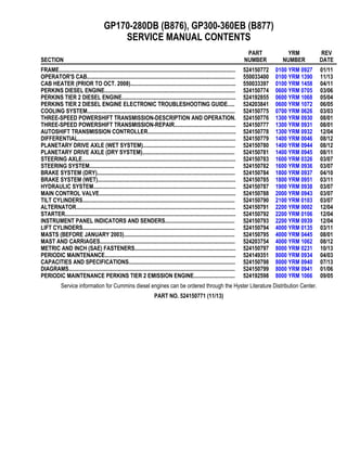
Lift Truck Weights
Unit kg lb
GP170DB 11,735 25,872
GDP80DB (GP190DB) 11,928 26,296
GDP90DB (GP210DB) 12,508 27,572
GDP100DB (GP230DB) 14,144 31,178
GP250DB 14,343 31,621
GDP120DB (GP280DB) 15,787 34,800
GDP130EB (GP300EB) 16,669 36,753
GDP140EB (GP330EB) 17,826 39,303
GDP160EB (GP360EB) 18,710 41,253
GDP80-120DB (GP170-280DB) models: 5335 mm (210 in.) mast, 2350 mm (92.5 in.) standard carriage,
65 [70] × 200 × 1220 mm (2.6 [2.76] × 8 × 48 in.) forks.
GDP130-160EB (GP300-360EB) models: 5310 mm (209 in.) mast, 2502 mm (98.5 in.) standard carriage, 90 ×
200 × 1375 mm (3.5 × 8 × 54 in.) forks.
1](data:image/gif;base64,R0lGODlhAQABAIAAAAAAAP///yH5BAEAAAAALAAAAAABAAEAAAIBRAA7)
Recommended
Recommended
More Related Content
Recently uploaded
Recently uploaded (20)
Featured
Featured (20)
YALE (B877) GP360EB LIFT TRUCK Service Repair Manual.pdf
- 1. GP170-280DB (B876), GP300-360EB (B877) SERVICE MANUAL CONTENTS SECTION PART NUMBER YRM NUMBER REV DATE FRAME............................................................................................................................ 524150772 0100 YRM 0927 01/11 OPERATOR'S CAB........................................................................................................ 550033400 0100 YRM 1390 11/13 CAB HEATER (PRIOR TO OCT. 2008).......................................................................... 550033397 0100 YRM 1458 04/11 PERKINS DIESEL ENGINE............................................................................................ 524150774 0600 YRM 0705 03/06 PERKINS TIER 2 DIESEL ENGINE................................................................................ 524192855 0600 YRM 1068 05/04 PERKINS TIER 2 DIESEL ENGINE ELECTRONIC TROUBLESHOOTING GUIDE..... 524203841 0600 YRM 1072 06/05 COOLING SYSTEM........................................................................................................ 524150775 0700 YRM 0626 03/03 THREE-SPEED POWERSHIFT TRANSMISSION-DESCRIPTION AND OPERATION. 524150776 1300 YRM 0930 08/01 THREE-SPEED POWERSHIFT TRANSMISSION-REPAIR........................................... 524150777 1300 YRM 0931 08/01 AUTOSHIFT TRANSMISSION CONTROLLER.............................................................. 524150778 1300 YRM 0932 12/04 DIFFERENTIAL............................................................................................................... 524150779 1400 YRM 0046 08/12 PLANETARY DRIVE AXLE (WET SYSTEM)................................................................. 524150780 1400 YRM 0944 08/12 PLANETARY DRIVE AXLE (DRY SYSTEM)................................................................. 524150781 1400 YRM 0945 08/11 STEERING AXLE............................................................................................................ 524150783 1600 YRM 0326 03/07 STEERING SYSTEM...................................................................................................... 524150782 1600 YRM 0936 03/07 BRAKE SYSTEM (DRY)................................................................................................. 524150784 1800 YRM 0937 04/10 BRAKE SYSTEM (WET)................................................................................................. 524150785 1800 YRM 0951 03/11 HYDRAULIC SYSTEM.................................................................................................... 524150787 1900 YRM 0938 03/07 MAIN CONTROL VALVE................................................................................................ 524150788 2000 YRM 0943 03/07 TILT CYLINDERS........................................................................................................... 524150790 2100 YRM 0103 03/07 ALTERNATOR................................................................................................................ 524150791 2200 YRM 0002 12/04 STARTER........................................................................................................................ 524150792 2200 YRM 0106 12/04 INSTRUMENT PANEL INDICATORS AND SENDERS................................................. 524150793 2200 YRM 0939 12/04 LIFT CYLINDERS........................................................................................................... 524150794 4000 YRM 0135 03/11 MASTS (BEFORE JANUARY 2003).............................................................................. 524150795 4000 YRM 0445 08/01 MAST AND CARRIAGES............................................................................................... 524203754 4000 YRM 1062 08/12 METRIC AND INCH (SAE) FASTENERS....................................................................... 524150797 8000 YRM 0231 10/13 PERIODIC MAINTENANCE............................................................................................ 524149351 8000 YRM 0934 04/03 CAPACITIES AND SPECIFICATIONS........................................................................... 524150798 8000 YRM 0940 07/13 DIAGRAMS..................................................................................................................... 524150799 8000 YRM 0941 01/06 PERIODIC MAINTENANCE PERKINS TIER 2 EMISSION ENGINE............................. 524192598 8000 YRM 1066 09/05 Service information for Cummins diesel engines can be ordered through the Hyster Literature Distribution Center. PART NO. 524150771 (11/13)
- 2. 8000 YRM 940 Lift Truck Weights Lift Truck Weights Unit kg lb GP170DB 11,735 25,872 GDP80DB (GP190DB) 11,928 26,296 GDP90DB (GP210DB) 12,508 27,572 GDP100DB (GP230DB) 14,144 31,178 GP250DB 14,343 31,621 GDP120DB (GP280DB) 15,787 34,800 GDP130EB (GP300EB) 16,669 36,753 GDP140EB (GP330EB) 17,826 39,303 GDP160EB (GP360EB) 18,710 41,253 GDP80-120DB (GP170-280DB) models: 5335 mm (210 in.) mast, 2350 mm (92.5 in.) standard carriage, 65 [70] × 200 × 1220 mm (2.6 [2.76] × 8 × 48 in.) forks. GDP130-160EB (GP300-360EB) models: 5310 mm (209 in.) mast, 2502 mm (98.5 in.) standard carriage, 90 × 200 × 1375 mm (3.5 × 8 × 54 in.) forks. 1
- 3. Capacities 8000 YRM 940 Capacities Item Quantity Engine Oil, Perkins Diesel 1006-60, With Oil Filter 13.2 liter (13.9 qt) Engine Oil, Perkins 1006-60T, With Oil Filter 14.2 liter (15 qt) Engine Oil, Perkins 1106C-E60 TA Tier 2, With Oil Filter 14.2 liter (15 qt) Engine Oil, Cummins QSB5.9-30 and B LPG Plus, With Oil Filter 16.3 liter (17.2 qt) Cooling System, Perkins 1006-60 26 liter (27.5 qt) Cooling System, Perkins 1006-60T 31 liter (32.8 qt) Cooling System, Perkins 1106C-E60 TA Tier 2 25.5 liter (27 qt) Cooling System, Cummins 25.5 liter (27 qt) Hydraulic Tank (FULL mark) GDP80-120DB (GP170-280DB) 109 liter (28.8 gal) GDP130-160EB (GP300-360EB) 109 liter (28.8 gal) Hydraulic System (Total Capacity) GDP80-120DB (GP170-280DB) 139 liter (36.7 gal) GDP130-160EB (GP300-360EB) 139 liter (36.7 gal) Transmission 16.5 liter (17.4 qt) Drive Axle and Differential Dry Brake System GDP80-120DB (GP170-280DB) 19 liter (20 qt) GDP130-160EB (GP300-360EB) 21 liter (21.1 qt) Wet Brake System GDP80-120DB (GP170-280DB) 19 liter (20 qt) GDP130-160EB (GP300-360EB) 21 liter (21.1 qt) Planetary Gears GDP80-120DB (GP170-280DB) 2.8 liter (3.0 qt) each GDP130-160EB (GP300-360EB) 2.4 liter (2.5 qt) each Fuel Tank (Diesel Engines) 128 liter (33.8 gal) LPG Tank LPG HD-10 77 liter (20.3 gal) 2
- 4. 8000 YRM 940 Engine Specifications Engine Specifications PERKINS DIESEL Item Specification Type Perkins 1006-60, 1006-60T and 1106C-E60 TA, Tier 2 Numbers of Cylinders 6 Firing Order 1-5-3-6-2-4 Bore 100 mm (3.937 in.) Stroke 127 mm (5.000 in.) Displacement 6 liter (366 in.3 ) Compression Ratio 17.25:1 Oil Pressure (Minimum, at 2200 rpm and normal operating temperature) 280 kPa (40 psi) Governed Speed (Full power and normal operating temperature) 1006-60 2200 rpm with load, 2310 ±50 no load 1006-60T 2300 rpm with load, 2415 ±50 no load Governed Speed (To high idle) 1106C-E60 TA, Tier 2 2415 ±10 Idle Speed 1006-60 725 to 775 rpm 1006-60T 725 to 775 rpm 1106C-E60 TA, Tier 2 740 to 760 rpm Stall Speed (Broken-in Engine) 1006-60 1925 ±50 rpm 1006-60T/1106C-E60 TA, Tier 2 2095 ±50 rpm Fuel Injection Timing 23° BTDC (Static) Thermostat Begin to open 80 to 84°C (176 to 183°F) Fully open 96°C (205°F) Valve Clearance (Cold) Intake 0.20 mm (0.008 in.) Exhaust 0.45 mm (0.018 in.) 3
- 5. https://www.aservicemanualpdf.com/ My Dear Friend! Thank you very much for visiting. Full manual if required, please enter the following URL into your browser. https://www.aservicemanualpdf.com/
- 6. Engine Specifications 8000 YRM 940 CUMMINS DIESEL/LPG Item Specification Type Cummins B LPG Plus Cummins QSB5.9-30 Number of Cylinders 6 6 Firing Order 1-5-3-6-2-4 1-5-3-6-2-4 Bore 102 mm (4.02 in.) 102 mm (4.02 in.) Stroke 120 mm (4.62 in.) 120 mm (4.62 in.) Displacement 5.88 liter (359 in.3 ) 5.88 liter (359 in.3 ) Compression Ratio 9.25:1 18:1 Oil Pressure (Minimum, at 2500 rpm and normal operating temperature) 345 kPa (50 psi) 345 kPa (50 psi) Oil Pressure (At low idle) 69 kPa (10 psi) 69 kPa (10 psi) Governed Speed (Full power at Normal Operating Temperature) GDP80-120DB, GDP130-160EB 2500 rpm with load 2600 ±50 no load 2300 rpm with load 2450±30 no load GP170-280DB, GP300-360EB 2500 rpm with load 2600 ±50 no load 2500 rpm with load 2600±50 no load Idle Speed 850 rpm±2% 725 ±2% Stall Speed (Broken-in Engine) 1950 to 2100 rpm 1950 to 2100 rpm Thermostat Begin to open 83°C (181°F) 83°C (181°F) Fully open 91°C (196°F) 91°C (196°F) Valve Clearance (Cold) Intake 0.305 mm (0.012 in.) 0.25 mm (0.01 in.) Exhaust 0.61 mm (0.024 in.) 0.51 mm (0.02 in.) 4
- 7. 8000 YRM 940 Hydraulic System Hydraulic System Item Quantity Perkins Hydraulic Pump Capacity @ 2300 rpm for turbo, 2200 rpm for nonturbo Main Section @ 21 MPa (3045 psi) 1006-60T/1106C-E60 TA 192 liter/min (51 gal/min) 1006-60 160 liter/min (42.3 gal/min) Steering/Aux Section @ 19.3 MPa (2800 psi) 1006-60T/1106C-E60 TA 93 liter/min (24.6 gal/min) 1006-60 78 liter/min (20.6 gal/min) Cummins Diesel Hydraulic Pump Capacity @ 2300 rpm Main Section @ 21 MPa (3045 psi) 192 liter/min (51 gal/min) Steering/Aux Section @ 19.3 MPa (2800 psi) 93 liter/min (24.6 gal/min) Cummins LPG Hydraulic Pump Capacity @ 2500 rpm Main Section @ 21 MPa (3045 psi) 183 liter/min (48.3 gal/min) Steering/Aux Section @ 19.3 MPa (2800 psi) 89 liter/min (23.5 gal/min) Relief Pressures * Main Control Valve Lift Circuit 21.0 MPa (3045 psi) Tilt and Auxiliary Circuits 19.3 MPa (2800 psi) Steering Circuit 16.5 MPa (2400 psi) ECH Functions 14.0 MPa (2030 psi) *Oil temperature 60°C (140°F) 5
- 8. Tire Sizes 8000 YRM 940 Electrical System All Models 24 Volt, Negative Ground Alternator Output at 24°C (75°F) 21 amps at 750 rpm All Engines 76 amps at 2200 rpm Tire Sizes NOTE: Refer to Truck Nameplate for correct tire pres- sure. Model Tire Size Tire Pressure GDP80-90DB (GP170-210DB) 9.00 × 20-12 ply 690 kPa (100 psi) GDP80-90DB (GP170-210DB) 9.00 × 20-14 ply 900 kPa (130 psi) GDP100-120DB (GP230-280DB) 10.00 × 20-12 ply 690 kPa (100 psi) GDP100-120DB (GP230-280DB) 10.00 × 20-16 ply 900 kPa (130 psi) GDP130EB (GP300EB) 11.00 × 20-14 ply 690 kPa (100 psi) GDP130-160EB (GP300-360EB) 12.00 × 20-16 ply 1000 kPa (145 psi) All Michelin XZM Radial Tires 1000 kPa (145 psi) 6
- 9. 8000 YRM 940 Mast Speeds Mast Speeds PERKINS DIESEL Lifting Lifting Lifting Lowering 1006.60 1006.60T 1106C-E60 TA 1006.60, 1006.60T and 1106C-E60 TA No Load Rated Load No Load Rated Load No Load Rated Load No Load Rated Load Unit m/ sec ft/ min m/ sec ft/ min m/ sec ft/ min m/ sec ft/ min m/ sec ft/ min m/ sec ft/ min m/ sec ft/ min m/ sec ft/ min GP170DB 0.63 124 0.41 80 0.73 143 0.48 96 0.73 143 0.48 96 0.48 95 0.50 98 GDP80DB (GP190DB) 0.63 124 0.41 80 0.73 143 0.48 96 0.73 143 0.48 96 0.48 95 0.50 98 GDP90DB (GP210DB) 0.63 124 0.41 80 0.73 143 0.48 96 0.73 143 0.48 96 0.48 95 0.50 98 GDP100DB (GP230DB) 0.53 104 0.36 70 0.56 110 0.38 74 0.53 104 0.34 67 0.46 91 0.49 97 GP250DB 0.53 104 0.36 70 0.56 110 0.38 74 0.53 104 0.34 67 0.46 91 0.49 97 GDP120DB (GP280DB) 0.53 104 0.36 70 0.56 110 0.38 74 0.53 104 0.34 67 0.46 91 0.49 97 GDP130EB (GP300EB) - - - - 0.46 91 0.30 59 0.44 87 0.29 57 0.44 87 0.48 95 GDP140EB (GP330EB) - - - - 0.46 91 0.30 59 0.44 87 0.29 57 0.44 87 0.48 95 GDP160EB (GP360EB) - - - - 0.46 91 0.30 59 0.44 87 0.29 57 0.44 87 0.48 95 7
- 10. Mast Speeds 8000 YRM 940 CUMMINS DIESEL/LPG Lifting Lifting Lowering B LPG Plus QSB5.9-30 B LPG Plus/QSB5.9-30 No Load Rated Load No Load Rated Load No Load Rated Load Unit m/ sec ft/ min m/ sec ft/ min m/ sec ft/ min m/ sec ft/ min m/ sec ft/ min m/ sec ft/ min GP170DB 0.69 136 0.37 73 0.73 143 0.48 95 0.48 95 0.50 98 GDP80DB (GP190DB) 0.69 136 0.37 73 0.73 143 0.48 95 0.48 95 0.50 98 GDP90D (GP210DB) 0.69 136 0.37 73 0.73 143 0.48 95 0.48 95 0.50 98 GDP100DB (GP230DB) 0.50 98 0.26 51 0.53 104 0.46 91 0.46 91 0.49 97 GP250DB 0.50 98 0.26 51 0.53 104 0.46 91 0.46 91 0.49 97 GDP120DB (GP280DB) 0.50 98 0.26 51 0.53 104 0.46 91 0.46 91 0.49 97 GDP130EB (GP300EB) 0.41 81 0.22 43 0.44 87 0.29 57 0.44 87 0.48 95 GDP140EB (GP330EB) 0.41 81 0.22 43 0.44 87 0.29 57 0.44 87 0.48 95 GDP160EB (GP360EB) 0.41 81 0.22 43 0.44 87 0.29 57 0.44 87 0.48 95 8
- 11. 8000 YRM 940 Torque Specifications, Perkins Diesel Torque Specifications, Cummins Diesel LUBRICATION SYSTEM Plug, Oil Sump, Aluminum Oil Pan 60 N•m (44 lbf ft) Plug, Oil Sump, Steel Oil Pan 80 N•m (59 lbf ft) All other Torque Specifications are found in Cummins Engine Manual. Contact Cummins Engine for any torque specifications not listed for this engine. Torque Specifications, Perkins Diesel ENGINE Cylinder Head Assembly Capscrews, Cylinder Head Special Procedure (See the section Perkins Diesel Engines, 1004-42 (AR), 1006-60 (YG), 1006-60T (YH) 600 YRM 705) Fasteners, Rocker Arm Brackets Aluminum 40 N•m (30 lbf ft) Cast Iron 75 N•m (55 lbf ft) Cap Nuts, Valve Cover 20 N•m (15 lbf ft) Capscrews, Inlet Manifold to Cylinder Head 44 N•m (32 lbf ft) Nuts (cadmium plated) Exhaust Manifold to Cylinder Head 44 N•m (32 lbf ft) Capscrews, Engine Lift Brackets 44 N•m (32 lbf ft) Piston and Connecting Rod Assemblies Nuts, Connecting Rods 125 N•m (92 lbf ft) Capscrews, Connecting Rods 155 N•m (114 lbf ft) Banjo Bolts, Piston Cooling Jets 27 N•m (20 lbf ft) Crankshaft Assembly Capscrews, Main Bearings 265 N•m (195 lbf ft) Capscrews, Crankshaft Pulley 115 N•m (85 lbf ft) Capscrews, Viscous Damper to Crankshaft Pulley 75 N•m (55 lbf ft) Capscrews, Damper to Crankshaft Pulley 35 N•m (26 lbf ft) Capscrews, Rear Oil Seal Housing to Engine Block 22 N•m (16 lbf ft) Capscrews, Bridge Piece to Cylinder Block 16 N•m (12 lbf ft) Capscrews, Rear Oil Seal Housing to Bridge Piece 13 N•m (10 lbf ft) Torx-head screw, Rear Oil Seal Housing to Engine Block 18 N•m (13 lbf ft) Timing Case and Drive Assembly Capscrews, Timing Case to Engine Block M8 22 N•m (16 lbf ft) M10 44 N•m (32 lbf ft) Capscrews, Hub of Idler Gear 44 N•m (32 lbf ft) Capscrew, Camshaft Gear 95 N•m (70 lbf ft) Capscrews, Timing Case Cover to Timing Case 22 N•m (16 lbf ft) Nuts, Timing Case Cover to Timing Case 22 N•m (16 lbf ft) Turbocharger Nuts, Turbocharger to Manifold 44 N•m (32 lbf ft) 9
- 12. Torque Specifications, Perkins Diesel 8000 YRM 940 Lubrication System Plug, Oil Sump 34 N•m (25 lbf ft) Capscrews, Oil Pump to Front Bearing Cap 22 N•m (16 lbf ft) Capscrews, Cover for Oil Pump 28 N•m (21 lbf ft) Fasteners, Oil Sump 22 N•m (16 lbf ft) Fuel System Nuts, High-pressure Fuel Lines 22 N•m (16 lbf ft) Bolt Leak-off Connection 9 N•m (7 lbf ft) Capscrews, Fuel Lift Pump 22 N•m (16 lbf ft) Nut for Fuel Injector Body 40 N•m (30 lbf ft) Capscrews for Gear of Fuel Injection Pump 28 N•m (21 lbf ft) Special (Torx-head) Screws for the Gear of the Fuel Injection Pump 22 N•m (16 lbf ft) Nuts for Flange of Fuel Injection Pump 22 N•m (16 lbf ft) Locking Screw of Lucas DP 200 Fuel Injection Pump 10 N•m (7 lbf ft) Cooling System Capscrews for Fan Drive Housing to Timing Case 44 N•m (32 lbf ft) Capscrews, Fan Drive Pulley to Hub M8 22 N•m (16 lbf ft) Capscrews, Fan Drive Pulley to Hub M10 44 N•m (32 lbf ft) Capscrews, Fan 22 N•m (16 lbf ft) Flywheel and Housing Capscrews, Flywheel to Crankshaft 105 N•m (77 lbf ft) Capscrews, Cast Iron Flywheel Housing to Cylinder Block: Head Stamped 8.8 (M10) 44 N•m (32 lbf ft) Head Stamped 8.8 (M12) 75 N•m (55 lbf ft) Head Stamped 10.9 (M10) 63 N•m (46 lbf ft) Head Stamped 10.9 (M12) 115 N•m (85 lbf ft) Capscrews, Aluminum Flywheel Housing to Cylinder Block 70 N•m (52 lbf ft) Capscrews, Flywheel Housing to Cylinder Block (Paper Joint) 70 N•m (52 lbf ft) Aspiration System Nuts, Turbocharger to Manifold 44 N•m (32 lbf ft) Electrical Equipment Nut, Alternator Pulley: Lucas CAV AC5RA and AC4RS 55 N•m (41 lbf ft) Thin nut A127 and Motorola pulley 22 mm A/F 60 N•m (44 lbf ft) Thick nut A127 and Motorola pulley 22 mm A/F 80 N•m (59 lbf ft) Fueled Start Aid to Induction Manifold 31 N•m (23 lbf ft) Nut/screw, Starter Motor 31 N•m (23 lbf ft) Auxiliary Equipment Nut, Air Compressor Drive Gear to Com- pressor Drive Shaft 120 N•m (89 lbf ft) Nut, (30mm A/F) Air Compressor Gears 130 N•m (96 lbf ft) Capscrew, Bracket to Idler Hub 60 N•m (44 lbf ft) Capscrew, Bracket to Timing Case 35 N•m (26 lbf ft) 10
- 13. 8000 YRM 940 Torque Specifications, General Torque Specifications, General TRANSMISSION Nuts, Mount Bolts for Isolator 155 N•m (114 lbf ft) Capscrews, Mount Bracket to Transmission 270 N•m (200 lbf ft) Capscrews, Transmission to Flywheel Housing Perkins 31 N•m (23 lbf ft) Cummins 25 N•m (19 lbf ft) Capscrews, Drive Plate to Flywheel 36 N•m (26.5 lbf ft) Nut, Output Yoke 270 to 339 N•m (200 to 250 lbf ft) Capscrews, Drive Plate to Torque Convertor 50 N•m (37 lbf ft) Oil Screen Assembly 14 to 20 N•m (10 to 15 lbf ft) Oil Filter 27 to 34 N•m (20 to 25 lbf ft) See the sections Three-Speed Powershift Transmission, Repairs 1300 YRM 931 and Transmission 1300 YRM 1082 for other torque values. DRIVELINE AND AXLE Capscrews, Universal Yoke 50 N•m (37 lbf ft) Bolts, Axle to Frame 920 N•m (679 lbf ft) Nuts, Wheel (Front and Rear) 640 to 680 N•m (472 to 502 lbf ft) DIFFERENTIAL See the section Differential 1400 YRM 46. BRAKES - WET See the sections Planetary Drive Axle, (Wet System) 1400 YRM 944 and Wet Brake System 1800 YRM 951. BRAKES - DRY Air Fittings in Air Chambers 34 N•m (25 lbf ft) Nuts Air Chamber Ring Clamps GDP80-120DB (GP170-280DB) 27 to 34 N•m (20 to 25 lbf ft) GDP130-160EB (GP300-360EB) 34 to 47 N•m (25 to 35 lbf ft) Jam Nut, Clevis 47 to 68 N•m (35 to 50 lbf ft) Lock Nuts, Air Chamber Studs 135 to 156 N•m (100 to 115 lbf ft) Capscrew, Brake Anchor Pin 14 N•m (10 lbf ft) Capscrew, Spider See the section Dry Brake System 1800 YRM 937. STEERING Nut, Steering Wheel 68 N•m (50 lbf ft) Capscrews, Steer Cylinder Mount 435 N•m (321 lbf ft) Capscrews, Bearing Cap 75 N•m (55 lbf ft) Nut, Wheel Bearing Initial 203 N•m (150 lbf ft) Final 34 N•m (25 lbf ft) Note: Torque lock nut to Initial torque while rotating wheel hub. Back off lock nut until wheel hub turns freely with no end play. (Torque at this point should be less than 27 N•m (20 lbf ft)). Retorque to Final torque and lock in place at first alignment position which occurs at or above final torque spec. Nuts, Wheel (Front and Rear) 640 to 680 N•m (472 to 502 lbf ft) Capscrews, Steer Axle Mount 270 N•m (199 lbf ft) HYDRAULIC SYSTEM Nuts, Hydraulic Pump Assembly 271 N•m (200 lbf ft) Capscrews, High-pressure Hose Flange 71 N•m (52 lbf ft) 11
- 14. Torque Specifications, General 8000 YRM 940 Capscrews, Suction Hose Flange 110 N•m (81 lbf ft) Nuts, Control Valve Assembly 7/16 in. 65 N•m (48 lbf ft) 1/2 in. 100 N•m (74 lbf ft) Jam Nut, Relief Valve Adjustment 55 to 67 N•m (41 to 49 lbf ft) Capscrews, Pump Mount 110 N•m (81 lbf ft) MAST Capscrews, Pivot Pin 435 N•m (321 lbf ft) Capscrew, Bearing Block 9 N•m (7 lbf ft) Capscrews, Bearing Block Bracket 44 N•m (32 lbf ft) Nuts, Wear Plate 53 N•m (39 lbf ft) Retainer, Lift Cylinder GDP80-90DB (GP170-210DB) 400 to 475 N•m (295 to 350 lbf ft) GDP100-120DB (GP230-280DB) 475 to 550 N•m (350 to 406 lbf ft) GDP130-160EB (GP300-360EB) 550 to 625 N•m (406 to 461 lbf ft) CARRIAGE Capscrew, Bearing Block 9 N•m (7 lbf ft) Capscrews, Bearing Block Bracket 44 N•m (32 lbf ft) Nut, Sideshift Cylinder Rod 675 N•m (498 lbf ft) TILT CYLINDERS Nut, Cylinder Rod GDP80-120DB (GP170-280DB) 950 to 983 N•m (701 to 725 lbf ft) GDP130-160EB (GP300-360EB) 1105 to 1140 N•m (815 to 841 lbf ft) Retainer GDP80-120DB (GP170-280DB) 542 to 610 N•m (400 to 450 lbf ft) GDP130-160EB (GP300-360EB) 610 to 675 N•m (450 to 498 lbf ft) Lock Nut, Rod End 66 N•m (49 lbf ft) Capscrew, Pin Anchor 165 N•m (122 lbf ft) FRAME Capscrew, Rear Counterweight, Lubricated 1900 N•m (1401 lbf ft) Nuts, Fender Counterweight, Lubricated 320 N•m (236 lbf ft) Capscrews, Frame Counterweight, Lubricated 640 N•m (472 lbf ft) WIPER ARMS, FRONT Capscrews, Bracket to Cab 20 to 25 N•m (14.7 to 18.4 lbf ft) Capscrews, Arm to Bracket 22 to 27 N•m (16.2 to 19.9 lbf ft) Capscrews, Blade to Arm 8 to 10 N•m (6 to 7.4 lbf ft) Capscrew, Arm Set 35 to 45 N•m (25.8 to 33.2 lbf ft) 12
- 15. 8000 YRM 940 Transmission Pressures (Powershift and Automatic) Transmission Pressures (Powershift and Automatic) A System Pressure 1100 to 1310 kPa (160 to 190 psi) H Torque Converter Supply (Port H is on the right-hand side of the transmission pump) 827 to 1034 kPa (120 to 150 psi) G Lubrication System Pressure 55 to 103 kPa (8 to 15 psi) C Reverse Clutch Pressure* 1100 to 1310 kPa (160 to 190 psi)** E Forward Clutch Pressure* 1100 to 1310 kPa (160 to 190 psi)** F 1st Speed Clutch Pressure 1100 to 1310 kPa (160 to 190 psi)** D 2nd Speed Clutch Pressure 1100 to 1310 kPa (160 to 190 psi)** B 3rd Speed Clutch Pressure 1100 to 1310 kPa (160 to 190 psi)** J Forward Pilot Pressure 1100 to 1310 kPa (160 to 190 psi) *Inching pressures 0 to 310 ±34 kPa (0 to 45 ±5 psi) Modulator pressure increases 414 to 758 kPa (60 to 110 psi) in 1.2 to 1.6 seconds. **The difference in clutch pressures for all clutches cannot be greater than 70 kPa (10 psi). 13
- 16. TE-10 Transmission Specifications 8000 YRM 940 TE-10 Transmission Specifications ELECTRICAL Electronic-controlled modulation solenoids VFS 2nd - VFS 1st/3rd - VFS Fwd - VFS Rev Coil resistance - 4.35 ±0.35 at 25°C (77°F) On/Off solenoids Total neutral and selector solenoids Coil resistance - 12V - 28 ±2 at 20°C (68°F) Coil resistance - 24V - 28 ±2 at 20°C (68°F) Speed sensor Type - Magneto resistive sensor. Sensing distance - 0 to 1.8 mm (0 to 0.07 in.) Sensor signal - Generates a square current with a fixed amplitude changing between 7 and 14 mA. Table 1. Temperature Sensor (In Speed Sensor) Resistance vs Temperature Ambient Temperature Resistance 55°C ( 67°F) 980 50°C ( 58°F) 1030 40°C ( 40°F) 1135 30°C ( 22°F) 1247 20°C ( 4°F) 1367 10°C (14°F) 1496 0°C (32°F) 1630 10°C (50°F) 1772 20°C (68°F) 1922 25°C (77°F) 2000 30°C (86°F) 2080 40°C (104°F) 2245 Table 1. Temperature Sensor (In Speed Sensor) Resistance vs Temperature (Continued) Ambient Temperature Resistance 50°C (122°F) 2417 60°C (140°F) 2597 70°C (158°F) 2785 80°C (176°F) 2980 90°C (194°F) 3182 100°C (212°F) 3392 110°C (230°F) 3607 120°C (248°F) 3817 125°C (257°F) 3915 130°C (266°F) 4008 140°C (284°F) 4166 150°C (302°F) 4280 HYDRAULIC COOLER LINES There is a minimum 19 mm (0.75 in.) internal diameter for lines and fittings. They must be suitable for operation from ambient temperature to 120°C (248°F) continu- ous operating temperature. They must withstand 30 bar (435 psi) continuous pressure and 45 bar (652 psi) in- termittent surges. Conform SAE J1019 and SAE J517, 100RI. TORQUE SPECIFICATIONS FOR LUBRICATED OR PLATED SCREW THREADS 14
- 17. 8000 YRM 940 TE-10 Transmission Specifications Table 2. Grade 5 Nom. Size Fine Thread Coarse Thread 0.2500 12.2 to 14.9 N•m (9 to 11 lbf ft) 10.8 to 13.6 N•m (8 to 10 lbf ft) 0.3125 21.7 to 27.1 N•m (16 to 20 lbf ft) 16.3 to 21.7 N•m (12 to 16 lbf ft) 0.3750 35.2 to 39.3 N•m (26 to 29 lbf ft) 31.2 to 33.9 N•m (23 to 25 lbf ft) 0.4375 55.6 to 61 N•m (41 to 45 lbf ft) 50.2 to 55.6 N•m (37 to 41 lbf ft) 0.5000 86.8 to 94.9 N•m (64 to 70 lbf ft) 77.3 to 85.4 N•m (57 to 63 lbf ft) 0.5625 123.4 to 135.6 N•m (91 to 100 lbf ft) 111.2 to 122 N•m (82 to 90 lbf ft) 0.6250 173.5 to 191.1 N•m (128 to 141 lbf ft) 153.2 to 168.1 N•m (113 to 124 lbf ft) 0.7500 302.3 to 332.1 N•m (223 to 245 lbf ft) 271.1 to 298.2 N•m (200 to 220 lbf ft) Table 3. Grade 8 Nom. Size Fine Thread Coarse Thread 0.2500 14.9 to 17.6 N•m (11 to 13 lbf ft) 12.2 to 14.9 N•m (9 to 11 lbf ft) 0.3125 38 to 43.4 N•m (28 to 32 lbf ft) 35.2 to 40.7 N•m (26 to 30 lbf ft) 0.3750 50.2 to 55.6 N•m (37 to 41 lbf ft) 44.7 to 48.8 N•m (33 to 36 lbf ft) 0.4375 78.6 to 86.8 N•m (58 to 64 lbf ft) 70.5 to 77.3 N•m (52 to 57 lbf ft) 0.5000 122 to 134.2 N•m (90 to 99 lbf ft) 108.4 to 119.3 N•m (80 to 88 lbf ft) 0.5625 173.5 to 191.1 N•m (128 to 141 lbf ft) 155.9 to 172.2 N•m (115 to 127 lbf ft) 0.6250 244 to 268.4 N•m (180 to 198 lbf ft) 215.5 to 237.2 N•m (159 to 175 lbf ft) 0.7500 427 to 470.4 N•m (315 to 347 lbf ft) 382.3 to 420.2 N•m (282 to 310 lbf ft) 15
- 18. TE-10 Transmission Specifications 8000 YRM 940 Table 4. Grades 8.8, 10.9, and 12.9 Grade 8.8 Grade 10.9 Grade 12.9 Nom. Size Coarse Thread Coarse Thread Coarse Thread M5 5 to 6 N•m (3.7 to 4.4 lbf ft) 7 to 8 N•m (5.2 to 5.9 lbf ft) 8 to 10 N•m (5.9 to 7.4 lbf ft) M6 8 to 10 N•m (5.9 to 7.4 lbf ft) 12 to 15 N•m (8.9 to 11.1 lbf ft) 13 to 16 N•m (9.6 to 11.8 lbf ft) M8 20 to 25 N•m (14.8 to 18.4 lbf ft) 30 to 35 N•m (22.1 to 25.8 lbf ft) 35 to 40 N•m (25.8 to 29.5 lbf ft) M10 40 to 50 N•m (29.5 to 36.9 lbf ft) 60 to 65 N•m (44.3 to 47.9 lbf ft) 65 to 75 N•m (47.9 to 55.3 lbf ft) M12 68 to 75 N•m (50.2 to 55.3 lbf ft) 100 to 110 N•m (73.8 to 81.1 lbf ft) 115 to 130 N•m (84.8 to 95.9 lbf ft) M14 110 to 125 N•m (81.1 to 92.2 lbf ft) 150 to 175 N•m (110.6 to 129.1 lbf ft) 180 to 210 N•m (132.8 to 154.9 lbf ft) M16 170 to 190 N•m (125.4 to 140.1 lbf ft) 240 to 275 N•m (177 to 202.8 lbf ft) 280 to 320 N•m (206.5 to 236 lbf ft) M20 320 to 360 N•m (236 to 265.5 lbf ft) 450 to 500 N•m (331.9 to 368.8 lbf ft) 525 to 600 N•m (387.2 to 442.5 lbf ft) M24 570 to 650 N•m (420.4 to 479.4 lbf ft) 800 to 900 N•m (590.1 to 663.8 lbf ft) 900 to 1050 N•m (663.8 to 774.4 lbf ft) M30 1150 to 1300 N•m (848.2 to 958.8 lbf ft) 1600 to 1800 N•m (1180.1 to 1327.6 lbf ft) 1850 to 2100 N•m (1364.5 to 1548.9 lbf ft) M36 2000 to 2250 N•m (1475.1 to 1659.5 lbf ft) 2749 to 3149 N•m (2027.6 to 2322.6 lbf ft) 3249 to 3699 N•m (2396.3 to 2728.2 lbf ft) 16
- 19. 8000 YRM 940 TE-10 Transmission Specifications Table 5. O-ring Port Plug Torque Chart Thread Size NPTF Torque 1/16 × 27 7 to 9 N•m (5 to 7 lbf ft) 1/8 × 27 9 to 14 N•m (7 to 10 lbf ft) 1/4 × 18 20 to 27 N•m (15 to 20 lbf ft) 3/8 × 18 34 to 41 N•m (25 to 30 lbf ft) 1/2 × 14 41 to 47 N•m (30 to 35 lbf ft) 3/4 × 10 or 14 54 to 61 N•m (40 to 45 lbf ft) 1 × 11 1/2 68 to 75 N•m (50 to 55 lbf ft) 1 1/4 × 11 1/2 81 to 88 N•m (60 to 65 lbf ft) M10 × 1 8 to 10 N•m (6 to 7 lbf ft) M14 × 1.5 10 to 12 N•m (7 to 9 lbf ft) M18 × 1.5 34 to 41 N•m (25 to 30 lbf ft) Table 5. O-ring Port Plug Torque Chart (Continued) Thread Size NPTF Torque M22 × 1.5 48 to 60 N•m (35 to 44 lbf ft) M33 × 2 112 to 140 N•m (83 to 103 lbf ft) Table 6. Pipe Plug Torque Chart Plugs (Permanent Plugs) Nom. Size Torque M18 × 1.5 6H 34 to 41 N•m (25 to 30 lbf ft) M26 × 1.5 6H 61 to 68 N•m (45 to 50 lbf ft) 17
- 20. 100 YRM 927 Description General This section has the description and repair procedures for the frame and connected parts. Included in this sec- tion are the frame, counterweight, fenders, hood, hy- draulic and fuel tanks, radiator/cooling section, opera- tor compartment, and cab. The instructions for removal and installation of the engine are included in this sec- tion. If the lift truck is fitted with a battery disconnect switch, open the switch if welding on the engine and remove the ECM (Engine Control Module). If welding on the lift truck chassis, verify the ground clamp is placed as close to the welding point as possible and NOT near the ECM. If it is necessary to weld near the ECM, remove the ECM from the engine to avoid damage from welding arc radiation. Description The frame is a one-piece weldment and has mounts for the counterweight, fenders, engine, transmission, axles, hydraulic and fuel tanks, operator’s compart- ment, and other parts. See Figure 1. 1. MAIN MOUNT 2. COUNTERWEIGHT MOUNT 3. STEERING MOUNT 4. DRIVE AXLE MOUNT 5. TILT CYLINDERS MOUNT 6. CAB CYLINDER MOUNT 7. CAB HINGE 8. MAST MOUNT 9. SIDE COUNTERWEIGHT MOUNT 10. FENDERS 11. CAB LATCH MOUNT Figure 1. Frame 1
- 21. Counterweight Repair 100 YRM 927 Counterweight Repair REMOVE WARNING The counterweight is heavy. Make sure that the crane and lifting devices have the capacity to lift 4600 kg (10,141 lb). 1. Remove the hood spine assembly. See Hood and Air Cleaner Repair. 2. GDP80-120DB (GP170-280DB) units only. Re- move the counterweight by placing an eyebolt through the hole in the top of the counterweight. See Figure 2. The eyebolt must be able to support the weight of the counterweight. Attach a lifting device to eyebolt. GDP130-160EB (GP300-360EB) units only. Re- move the fenders, noting shims used and location of shims. Remove the radiator fan, shroud, and hardware. Tilt the radiator away from the coun- terweight so there is clearance when removing the counterweight. See Figure 2. Install eyebolt into the top of the counterweight. The eyebolt must be able to support the weight of the counterweight. At- tach lifting device. 3. Remove the single capscrew from the rear of the counterweight. Remove the counterweight from the frame. INSTALL WARNING The counterweight is heavy. Make sure that the crane and lifting devices have the capacity to lift 4600 kg (10,141 lb). 1. Put a chain into top opening of the counterweight and attach chain to a lifting device. See Figure 2. 2. GDP130-160EB (GP300-360EB) units only. In- stall the radiator hardware. Tilt the radiator ahead so there is clearance for the chain that is installed through the counterweight. 3. Install the counterweight on the frame. Install the capscrew, lockwasher, and flat washer to fasten the counterweight to the frame. Tighten the capscrew to 1140 N•m (841 lbf ft). FENDERS Remove WARNING The fenders are part of the lift truck counterweight and are very heavy. Make sure any lifting devices have the capacity to lift 1750 kg (3858 lb). Make sure the fender is balanced and supported by the chain. The fenders are not of a regular shape and can be difficult to handle. 1. Remove the capscrews, washers, and nuts that fas- ten the fender to the frame mount. Install eyebolts in the mount holes. Use mount holes to pick up fender from frame. 2. Fasten a lifting device to the eyebolts. Operate the lifting device and lift the fender away from the frame. Install 1. Install eyebolts in the fenders as described in Re- move, Step 1. Fasten a lifting device to the eye- bolts. 2. Raise the fender to the lift truck. Align the eyebolts in the fender with the holes in the fender mount on the frame. Shim fenders to correct height. Lower the fender to the fender mount and remove the lift- ing device and the eyebolts. 3. Install the capscrews, washers, and nuts that hold the fender to the frame. Tighten the nuts to 320 N•m (236 lbf ft). 2
- 22. 100 YRM 927 Counterweight Repair 1. LH FENDER COUNTERWEIGHT 2. RH FENDER COUNTERWEIGHT 3. CAPSCREW 4. WASHER 5. NUT 6. WASHER 7. TOW PIN 8. GRIP 9. PIN 10. PIN 11. SHIM 12. WASHER 13. LOCKWASHER 14. WASHER 15. SHIM 16. SHIM 17. SHIM 18. COUNTERWEIGHT 19. CAPSCREW 20. SLAB COUNTERWEIGHT 21. PLATE 22. LOCKWASHER 23. CAPSCREW 24. RH SLAB COUNTERWEIGHT 25. LH SLAB COUNTERWEIGHT 26. CAPSCREW 27. WASHER 28. WASHER 29. NUT 30. ISOLATOR 31. LOCKWASHER 32. NUT 33. RUBBER STOP Figure 2. Counterweight Mounts 3
- 23. Hood and Air Cleaner Repair 100 YRM 927 SIDE COUNTERWEIGHTS GDP130-160EB (GP300-360EB) The counterweights located on either side of the lift truck are fastened to the frame by large capscrews. Normally these counterweights will never have to be re- moved or replaced on the lift truck. SIDE COUNTERWEIGHT, REPLACE If replacement of the side counterweight is required, do the following procedure: WARNING The side counterweights are heavy. Each side counterweight weighs approximately 560 kg (1235 lb). Make sure that the crane and lifting devices have the capacity to lift 908 kg (2433 lb). 1. Remove the extension covers from both side tanks. 2. Remove each counterweight capscrew and replace it in turn with a long stud. The studs must protrude about 152 mm (6 in.) beyond the counterweight. 3. Use a pry bar and carefully move the counterweight away from the frame about 50 mm (2 in.). Install a nylon lifting sling securely around the counter- weight and attach it to a lifting device. WARNING Make sure the counterweight is balanced and can- not fall from the sling when the sling is raised. 4. Carefully lift the counterweight away from the lift truck frame and lower the counterweight to the floor. 5. For installation of the side counterweights, follow the above procedure in reverse order. Tighten the counterweight capscrews to 655 N•m (483 lbf ft). Hood and Air Cleaner Repair The hood and air cleaner assembly, which includes the rain cap or optional precleaner and inlet pipe, can be removed from the frame as a single unit, or pivoted out of the way for access. REMOVE NOTE: The hood and air cleaner assembly can be piv- oted out of the way to gain access to many components. In order to pivot hood and air cleaner assembly, remove 2 bolts, nuts, and washers at one side connecting hood to hood spine support and loosen the 2 bolts at oppo- site side. 1. Unlock hood with an allen wrench. 2. Open hood panel until gas spring locks hood panel in open position. 3. Attach a lifting device and sling to support hood spine and attaching components. See Figure 3 and Figure 4. 4. Loosen air intake hose to turbocharger at inlet side of turbocharger. 5. Loosen clamps at upper exhaust stack. 6. Remove bolts, nuts, washers, and bar washers that fasten hood spine to counterweight and hood sup- port. 7. Disconnect washer hoses from washer container and mark for reconnecting. 8. Disconnect the washer hoses from hood and air cleaner assembly. 9. Using lifting device, lift hood assembly from frame. Air filter assembly and exhaust stack will remain attached to hood and spine assembly. INSTALL Install the hood and air cleaner assembly in the reverse procedure of removal and align the hood as necessary during installation. Make sure the hood side panels close completely and that the cushioned screw stops (bumpers) are located correctly. 4
- 24. 100 YRM 927 Hood and Air Cleaner Repair 1. HOOD SPINE HARDWARE 2. HOOD SPINE 3. COUNTERWEIGHT 4. HOOD SPINE SUPPORT 5. AIR INTAKE HOSE 6. EXHAUST STACK CLAMP 7. RAIN CAP 8. GAS SPRING 9. HOOD PANEL 10. EXHAUST STACK Figure 3. Hood and Air Cleaner Assembly (B876 and B877) 5
- 25. Hood and Air Cleaner Repair 100 YRM 927 1. HOOD SPINE HARDWARE 2. HOOD SPINE 3. COUNTERWEIGHT 4. HOOD SPINE SUPPORT 5. AIR INTAKE HOSE 6. EXHAUST STACK CLAMP 7. RAINCAP 8. HOOD PANEL 9. EXHAUST STACK Figure 4. Hood and Air Cleaner (C876 and C877) 6
- 26. 100 YRM 927 Hydraulic Tank Repair Hydraulic Tank Repair The hydraulic tank is installed on the right side of the frame between the front and rear fenders. REMOVE 1. Remove the side cover between the bottom of the operator compartment and the top of the hydraulic tank. See Figure 5. If necessary, remove the drain plug at the bottom of the tank to drain the oil. See Figure 6 and Figure 7. 2. Remove the extension panel. NOTE: Do not remove items 14, 15, 16, and 17 from the tank. 3. Disconnect the hoses at the top elbow connection and at the side connection to the tank located on the inside of the frame. Use a pan to catch the oil that is in the hydraulic lines. Put tags on the lines for identification. Put caps on the open lines and the fittings. WARNING Make sure that the tank is supported by blocks be- fore removing the nuts and washers from the top of the tank. 4. Support the fuel tank with blocks from beneath. First, remove the three capscrews that fasten the bottom of the tank to the running board. Remove the three nuts and washers that hold the top of the tank to the frame. Install two lifting eyes at the outer holes. Attach a lifting device and support the tank. Lift the tank from the frame. 1. HYDRAULIC TANK 2. BATTERY BOX 3. FRAME 4. SIDE COVER 5. NUT AND WASHER 6. EXTENSION PANEL Figure 5. Hydraulic Tank and Battery Box 7
- 27. Hydraulic Tank Repair 100 YRM 927 1. WASHER (3) 2. LOCKWASHER (3) 3. BREATHER 4. FILTER HEAD 5. O-RING 6. DIPSTICK 7. O-RING 8. SEAL 9. SPRING 10. WASHER 11. FILTER 12. DRAIN PLUG 13. NUT (3) 14. ADAPTER 15. ADAPTER 16. HYDRAULIC TANK 17. O-RING 18. RETAINING RING 19. FITTING 20. FITTING 21. PLUG Figure 6. Hydraulic Tank (B876 and B877) 1. SIGHT GLASS 2. FILTER 3. FILTER HEAD 4. SPRING 5. O-RING 6. CAPSCREW 7. PLUG 8. BREATHER 9. WASHER 10. NUT 11. DRAIN PLUG 12. O-RING 13. HYDRAULIC TANK 14. COVER 15. SEAL 16. WASHER 17. CAPSCREW Figure 7. Hydraulic Tank (C876 and C877) 8
- 28. Thank you very much for your reading. Please Click Here Then Get More Information.
- 29. https://www.aservicemanualpdf.com/ My Dear Friend! Thank you very much for visiting. Full manual if required, please enter the following URL into your browser. https://www.aservicemanualpdf.com/