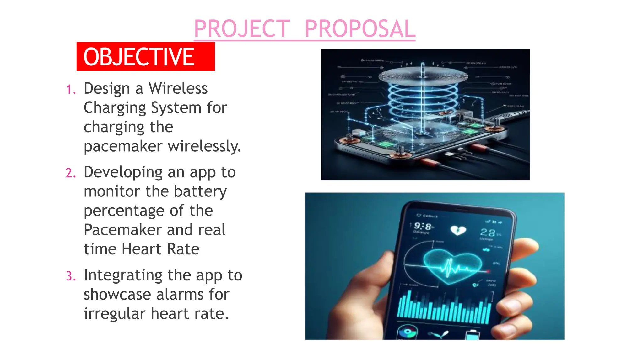
Development of a Wireless Charging System
for Implantable Pacemakers Integrated with
Real-Time Heart Rate Monitoring and Battery
indicator
PRESENTED BY
Joydeep Roy Chowdhury 27600320015
Pritam Bakshi 27600321027
Mukesh Kumar Kamat 27600320003
Sayak Ghoroi 27600321028
Under the supervision of
Dr. Satya Gopal Dinda
(Associate Professor , Dept. of ECE)
CONTENTS
INTRODUCTION
MOTIVATION
LITERATURE
SURVEY
PROJECT
PROPOSAL
METHODOLOGY
WORK DONE
FUTURE PLAN
REFERENCES
INTRODUCTION
 A pacemaker is a small, battery-operated device that helps
control an irregular heart rhythm.
 Functionality:
 It sends electricalpulsesto help the heart beat at a normal rate
and rhythm.
 Battery-Powered:
 Traditionally pacemakers rely on internal batteries for power,
which have a finitelifespan and requiresurgicalreplacement.
PACEMAKER.
 Critical Lifesaving Role:
 Pacemakers are crucial for
individuals with bradycardia (slow
heart rate) or tachycardia (fast
heart rate).
MOTIVATION FOR PROJECT
1) Complications – surgery replacement:
Studies show 40% of pacemaker patients experience discomfort during battery replacement. 5%
of pacemaker battery replacement surgeries result in complications. With 450,000 annual
procedures, our project aims to prevent 22,500 adverse events annually
2) Cost:
Pacemaker battery replacements cost $15,000 each; 15% of the 3 million patients
undergo surgery annually. Wireless charging could save the healthcare system $675
million yearly.
3) Minimising hostpital readmission:
Real-time monitoring can reduce hospital readmissions by 25%. Integrating this feature
could prevent 5,000 readmissions annually among pacemaker patients.
SL.
NO
.
Title Author /Year Remarks Published in
1 Adverse clinical events caused
by pacemaker battery
depletion: two case Reports
Junpeng Liu1* ,
Li Wen2, and
others
2020
The study underscores the serious consequences of
pacemaker battery depletion, advocating early
detection through ECG-based methods for improved
patient outcomes and safety.
BMC Cardiovascular
Disorders, Springer
Nature
2
Study on Wireless Power
Transfer Technology Toward the
Application for Cardiac
Pacemaker
Mengyang Li,
2022
Pioneering study: Wireless power transfer
technology investigated for cardiac pacemakers,
promising potential advancements in patient care
and device management.
Journal of China
Association of
Science &
Technology
3 Wireless powering efficiency of
deep-body implantable devices
V.Soares et.al
,
Elevating deep-body implant efficiency through
wireless powering—a breakthrough poised to
enhance device performance and extend lifespan.
IEEE
4
An Improved Novel Wireless
Power Transfer Method For
Pacemakers
Mrs.Sritha.PandM
aheswari.K,T,
2017
Revolutionizing pacemaker technology with an
innovative wireless power transfer method,
promising enhanced safety, efficiency, and patient
well-being.
International
Research Journal
of Engineering and
Technology
(IRJET)
5
Coil-based wireless power
transfer for implanted
pacemakers
M.D miftahul
Amri and Liya
yusrina sabila,
2023
Coil-based wireless power transfer for pacemakers:
a promising leap toward efficient, contactless
energy delivery, offering potential benefits in safety,
reliability, and patient comfort.
Journal
Teknik Elektro
LITERATURE REVIEW
PROJECT PROPOSAL
1. Design a Wireless
Charging System for
charging the
pacemaker wirelessly.
2. Developing an app to
monitor the battery
percentage of the
Pacemaker and real
time Heart Rate
3. Integrating the app to
showcase alarms for
irregular heart rate.
OBJECTIVE.
METHODOLOGY
PROJECT COMPONENTS
• TIP31C:
The TIP31C is an NPN power transistor designed for amplification and switching tasks in
electronic circuits. With a maximum collector current of 3A, it is suitable for moderate power
applications. Its TO-220 package allows convenient mounting on heat sinks for effective
thermal management.
• COPPER WIRE:
Copper wire is a versatile electrical conductor widely used in power transmission and
telecommunications. Its excellent conductivity and malleability make it an ideal material for crafting
efficient and durable wiring solutions. The metal's corrosion resistance further enhances its longevity,
ensuring reliable performance in various applications.
• ELECTROLYTIC CAPACITORS:
Electrolytic capacitors are electronic components that store and release electrical energy in circuits.
They utilize an electrolyte solution to enhance their capacitance, making them suitable for
applications requiring high capacitance values. Commonly used in power supply circuits, these
capacitors offer efficient energy storage and voltage regulation.
• NON- ELECTROLYTIC CAPACITORS:
A non-electrolytic capacitor is a type of capacitor that does not rely on an electrolyte for its operation.
Unlike electrolytic capacitors, which use a liquid electrolyte, non-electrolytic capacitors employ solid
materials as dielectrics, providing stability and longevity. Common types include ceramic capacitors,
film capacitors, and tantalum capacitors.
• DIODE:
A diode is a semiconductor device that allows current to flow in one direction only, exhibiting a
unidirectional electrical property. It typically consists of a cathode and an anode and is widely used in
electronic circuits for rectification, signal demodulation, and voltage regulation. Diodes play a crucial
role in controlling the direction of electrical current within electronic systems.
• RESISTANCE:
Resistance is the opposition or hindrance to the flow of electric current in a circuit, typically measured
in ohms. In broader contexts, it also refers to the act of opposing or withstanding external forces,
influences, or pressure.
• OP-AMP:
A sinewave frequency driver IC is an integrated circuit designed to generate and control sine wave
signals, commonly used in applications such as motor drives and power inverters for precise
frequency modulation.
• POWER SUPPLY:
Switched Mode Power Supply (SMPS) is an electronic circuit that efficiently converts and regulates
electrical power, commonly used to provide stable voltage outputs in various electronic devices.
• LED:
LEDs, or light-emitting diodes, are semiconductor devices that emit light when an
electric current passes through them, offering energy-efficient and durable lighting
solutions for various applications.
Circuit Diagram
Electro-magnetic
induction
Input
(DC)
Output
(DC)
Rectifier
Voltage
Regulator
Filter
Frequency
Driver IC
TIP 33C
Transistor
Transmitter
Coil
Receiver
Coil
69Khz
GND(Secondary)
GND(Primary)
HARDWARE MODEL
RESULT
 INPUT:
 INPUT VOLTAGE : 5 volt
 INPUT Current : 700mA
 Input DC Offset voltage:
3.3 V
 Operating Frequency = 69KHz
 OUTPUT CURRENT = 800mA
 Output Voltage
 AC output : Vpp = 35.8 Volt
 DC output: Vout = 15 Volt
Fig. O/P Voltage vs Time Graph
FUTURE
PLANS
 Micro-controller based wireless monitoring system.
Transfer of Data over Wi-Fi/BLE to Mobile application.
 Integrating with ECG sensor and Temperature sensor
to monitor real-time heart rate and body
temperature.
 Secured Charging System – This system will verify the
frequency of incoming signal.
 Develop Mobile Application for the user.
 Alarm system in the mobile app for irregular heart
rate.
REFERENCES
 J. Liu, W. Li, S. Yao, P. Zheng, S. Zhao, and J. Yang, “Adverse clinical events caused by pacemaker battery depletion: two case
reports,” BMC Cardiovascular Disorders, vol. 20, no. 1, Jul. 2020, doi: 10.1186/s12872-020-01622-x.
 V. Vulfin, S. Sayfan-Altman, and R. Ianconescu, “Wireless power transfer for a pacemaker application,” Journal of Medical
Engineering & Technology, vol. 41, no. 4, pp. 325–332, Mar. 2017, doi: 10.1080/03091902.2017.1299232.
 Y. Hao, Y. Li, D. Liao, and L. Yang, “Seven times replacement of permanent cardiac pacemaker in 33 years to maintain
adequate heart rate: a case report.,” PubMed, vol. 3, no. 21, p. 341, Dec. 2015, doi: 10.3978/j.issn.2305-5839.2015.11.35.
 P. Zimetbaum, B. J. Carroll, A. H. Locke, E. A. Secemsky, and M. L. Schermerhorn, “Lead-Related venous obstruction in
patients with implanted cardiac devices,” Journal of the American College of Cardiology, vol. 79, no. 3, pp. 299–308, Jan.
2022, doi: 10.1016/j.jacc.2021.11.017.
 “Trends in cardiac pacemaker batteries,” PubMed, Oct. 01, 2004. https://pubmed.ncbi.nlm.nih.gov/16943934/
 https://openheart.bmj.com/content/1/1/e000177
 www.google.com

Wireless Charger for implantable pacemakers.pptx

  • 1.
    Development of aWireless Charging System for Implantable Pacemakers Integrated with Real-Time Heart Rate Monitoring and Battery indicator PRESENTED BY Joydeep Roy Chowdhury 27600320015 Pritam Bakshi 27600321027 Mukesh Kumar Kamat 27600320003 Sayak Ghoroi 27600321028 Under the supervision of Dr. Satya Gopal Dinda (Associate Professor , Dept. of ECE)
  • 2.
  • 3.
    INTRODUCTION  A pacemakeris a small, battery-operated device that helps control an irregular heart rhythm.  Functionality:  It sends electricalpulsesto help the heart beat at a normal rate and rhythm.  Battery-Powered:  Traditionally pacemakers rely on internal batteries for power, which have a finitelifespan and requiresurgicalreplacement. PACEMAKER.  Critical Lifesaving Role:  Pacemakers are crucial for individuals with bradycardia (slow heart rate) or tachycardia (fast heart rate).
  • 4.
    MOTIVATION FOR PROJECT 1)Complications – surgery replacement: Studies show 40% of pacemaker patients experience discomfort during battery replacement. 5% of pacemaker battery replacement surgeries result in complications. With 450,000 annual procedures, our project aims to prevent 22,500 adverse events annually 2) Cost: Pacemaker battery replacements cost $15,000 each; 15% of the 3 million patients undergo surgery annually. Wireless charging could save the healthcare system $675 million yearly. 3) Minimising hostpital readmission: Real-time monitoring can reduce hospital readmissions by 25%. Integrating this feature could prevent 5,000 readmissions annually among pacemaker patients.
  • 5.
    SL. NO . Title Author /YearRemarks Published in 1 Adverse clinical events caused by pacemaker battery depletion: two case Reports Junpeng Liu1* , Li Wen2, and others 2020 The study underscores the serious consequences of pacemaker battery depletion, advocating early detection through ECG-based methods for improved patient outcomes and safety. BMC Cardiovascular Disorders, Springer Nature 2 Study on Wireless Power Transfer Technology Toward the Application for Cardiac Pacemaker Mengyang Li, 2022 Pioneering study: Wireless power transfer technology investigated for cardiac pacemakers, promising potential advancements in patient care and device management. Journal of China Association of Science & Technology 3 Wireless powering efficiency of deep-body implantable devices V.Soares et.al , Elevating deep-body implant efficiency through wireless powering—a breakthrough poised to enhance device performance and extend lifespan. IEEE 4 An Improved Novel Wireless Power Transfer Method For Pacemakers Mrs.Sritha.PandM aheswari.K,T, 2017 Revolutionizing pacemaker technology with an innovative wireless power transfer method, promising enhanced safety, efficiency, and patient well-being. International Research Journal of Engineering and Technology (IRJET) 5 Coil-based wireless power transfer for implanted pacemakers M.D miftahul Amri and Liya yusrina sabila, 2023 Coil-based wireless power transfer for pacemakers: a promising leap toward efficient, contactless energy delivery, offering potential benefits in safety, reliability, and patient comfort. Journal Teknik Elektro LITERATURE REVIEW
  • 6.
    PROJECT PROPOSAL 1. Designa Wireless Charging System for charging the pacemaker wirelessly. 2. Developing an app to monitor the battery percentage of the Pacemaker and real time Heart Rate 3. Integrating the app to showcase alarms for irregular heart rate. OBJECTIVE.
  • 7.
  • 8.
    PROJECT COMPONENTS • TIP31C: TheTIP31C is an NPN power transistor designed for amplification and switching tasks in electronic circuits. With a maximum collector current of 3A, it is suitable for moderate power applications. Its TO-220 package allows convenient mounting on heat sinks for effective thermal management. • COPPER WIRE: Copper wire is a versatile electrical conductor widely used in power transmission and telecommunications. Its excellent conductivity and malleability make it an ideal material for crafting efficient and durable wiring solutions. The metal's corrosion resistance further enhances its longevity, ensuring reliable performance in various applications. • ELECTROLYTIC CAPACITORS: Electrolytic capacitors are electronic components that store and release electrical energy in circuits. They utilize an electrolyte solution to enhance their capacitance, making them suitable for applications requiring high capacitance values. Commonly used in power supply circuits, these capacitors offer efficient energy storage and voltage regulation. • NON- ELECTROLYTIC CAPACITORS: A non-electrolytic capacitor is a type of capacitor that does not rely on an electrolyte for its operation. Unlike electrolytic capacitors, which use a liquid electrolyte, non-electrolytic capacitors employ solid materials as dielectrics, providing stability and longevity. Common types include ceramic capacitors, film capacitors, and tantalum capacitors.
  • 9.
    • DIODE: A diodeis a semiconductor device that allows current to flow in one direction only, exhibiting a unidirectional electrical property. It typically consists of a cathode and an anode and is widely used in electronic circuits for rectification, signal demodulation, and voltage regulation. Diodes play a crucial role in controlling the direction of electrical current within electronic systems. • RESISTANCE: Resistance is the opposition or hindrance to the flow of electric current in a circuit, typically measured in ohms. In broader contexts, it also refers to the act of opposing or withstanding external forces, influences, or pressure. • OP-AMP: A sinewave frequency driver IC is an integrated circuit designed to generate and control sine wave signals, commonly used in applications such as motor drives and power inverters for precise frequency modulation. • POWER SUPPLY: Switched Mode Power Supply (SMPS) is an electronic circuit that efficiently converts and regulates electrical power, commonly used to provide stable voltage outputs in various electronic devices. • LED: LEDs, or light-emitting diodes, are semiconductor devices that emit light when an electric current passes through them, offering energy-efficient and durable lighting solutions for various applications.
  • 10.
  • 11.
  • 12.
    RESULT  INPUT:  INPUTVOLTAGE : 5 volt  INPUT Current : 700mA  Input DC Offset voltage: 3.3 V  Operating Frequency = 69KHz  OUTPUT CURRENT = 800mA  Output Voltage  AC output : Vpp = 35.8 Volt  DC output: Vout = 15 Volt Fig. O/P Voltage vs Time Graph
  • 13.
    FUTURE PLANS  Micro-controller basedwireless monitoring system. Transfer of Data over Wi-Fi/BLE to Mobile application.  Integrating with ECG sensor and Temperature sensor to monitor real-time heart rate and body temperature.  Secured Charging System – This system will verify the frequency of incoming signal.  Develop Mobile Application for the user.  Alarm system in the mobile app for irregular heart rate.
  • 14.
    REFERENCES  J. Liu,W. Li, S. Yao, P. Zheng, S. Zhao, and J. Yang, “Adverse clinical events caused by pacemaker battery depletion: two case reports,” BMC Cardiovascular Disorders, vol. 20, no. 1, Jul. 2020, doi: 10.1186/s12872-020-01622-x.  V. Vulfin, S. Sayfan-Altman, and R. Ianconescu, “Wireless power transfer for a pacemaker application,” Journal of Medical Engineering & Technology, vol. 41, no. 4, pp. 325–332, Mar. 2017, doi: 10.1080/03091902.2017.1299232.  Y. Hao, Y. Li, D. Liao, and L. Yang, “Seven times replacement of permanent cardiac pacemaker in 33 years to maintain adequate heart rate: a case report.,” PubMed, vol. 3, no. 21, p. 341, Dec. 2015, doi: 10.3978/j.issn.2305-5839.2015.11.35.  P. Zimetbaum, B. J. Carroll, A. H. Locke, E. A. Secemsky, and M. L. Schermerhorn, “Lead-Related venous obstruction in patients with implanted cardiac devices,” Journal of the American College of Cardiology, vol. 79, no. 3, pp. 299–308, Jan. 2022, doi: 10.1016/j.jacc.2021.11.017.  “Trends in cardiac pacemaker batteries,” PubMed, Oct. 01, 2004. https://pubmed.ncbi.nlm.nih.gov/16943934/  https://openheart.bmj.com/content/1/1/e000177  www.google.com