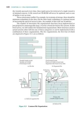
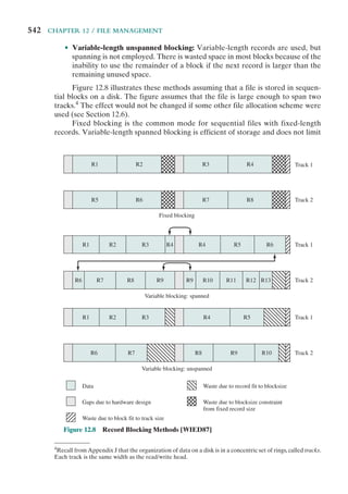
This document is the table of contents for the textbook "Operating Systems: Internals and Design Principles" by William Stallings. It lists the chapter titles and section headings that make up the book. The book covers topics such as computer system overview, operating system overview, processes, memory management, scheduling, input/output, file management, distributed systems, and computer security. It provides an in-depth look at operating system design principles and internals across multiple systems including Windows, Linux, UNIX, and embedded operating systems.


![1.4 / INTERRUPTS 23
The drawback to the preceding approach is that it does not take into account
relative priority or time-critical needs. For example, when input arrives from the
communications line, it may need to be absorbed rapidly to make room for more
input. If the first batch of input has not been processed before the second batch
arrives, data may be lost because the buffer on the I/O device may fill and overflow.
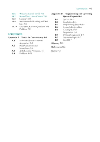
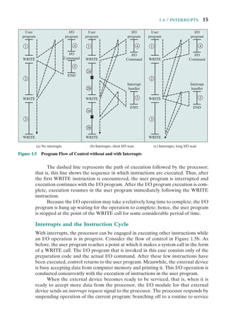
A second approach is to define priorities for interrupts and to allow an inter-
rupt of higher priority to cause a lower-priority interrupt handler to be interrupted
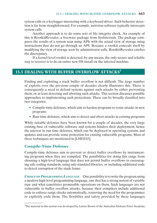
(Figure 1.12b). As an example of this second approach, consider a system with three
I/O devices: a printer, a disk, and a communications line, with increasing priorities of
2, 4, and 5, respectively. Figure 1.13, based on an example in [TANE06], illustrates
a possible sequence. A user program begins at t ⫽ 0. At t ⫽ 10, a printer interrupt
occurs; user information is placed on the control stack and execution continues at
the printer interrupt service routine (ISR). While this routine is still executing, at
t ⫽ 15 a communications interrupt occurs. Because the communications line has
higher priority than the printer, the interrupt request is honored. The printer ISR is
interrupted, its state is pushed onto the stack, and execution continues at the com-
munications ISR. While this routine is executing, a disk interrupt occurs (t ⫽ 20).
Because this interrupt is of lower priority, it is simply held, and the communications
ISR runs to completion.
When the communications ISR is complete (t ⫽ 25), the previous processor
state is restored, which is the execution of the printer ISR. However, before even a
single instruction in that routine can be executed, the processor honors the higher-
priority disk interrupt and transfers control to the disk ISR. Only when that routine
is complete (t ⫽ 35) is the printer ISR resumed. When that routine completes
(t ⫽ 40), control finally returns to the user program.
User program
Printer
interrupt service routine
Communication
interrupt service routine
Disk
interrupt service routine
t ⫽
10
t ⫽ 40
t ⫽
15
t ⫽ 25
t ⫽ 25
t ⫽
35
t ⫽ 0
Figure 1.13 Example Time Sequence of Multiple Interrupts](https://image.slidesharecdn.com/williamstallingsoperatingsystemsinter-230528124001-c4cbce35/85/William_Stallings_Operating_SystemsInter-pdf-45-320.jpg)


![26 CHAPTER 1 / COMPUTER SYSTEM OVERVIEW
memory systems exists that satisfies conditions (a) through (c). Fortunately, condi-
tion (d) is also generally valid.
The basis for the validity of condition (d) is a principle known as locality of
reference [DENN68]. During the course of execution of a program, memory refer-
ences by the processor, for both instructions and data, tend to cluster. Programs
typically contain a number of iterative loops and subroutines. Once a loop or subrou-
tine is entered, there are repeated references to a small set of instructions. Similarly,
operations on tables and arrays involve access to a clustered set of data bytes. Over
a long period of time, the clusters in use change, but over a short period of time, the
processor is primarily working with fixed clusters of memory references.
Accordingly, it is possible to organize data across the hierarchy such that the
percentage of accesses to each successively lower level is substantially less than that of
the level above. Consider the two-level example already presented. Let level 2 mem-
ory contain all program instructions and data. The current clusters can be temporarily
placed in level 1. From time to time, one of the clusters in level 1 will have to be
swapped back to level 2 to make room for a new cluster coming in to level 1. On aver-
age, however, most references will be to instructions and data contained in level 1.
This principle can be applied across more than two levels of memory. The
fastest, smallest, and most expensive type of memory consists of the registers inter-
nal to the processor. Typically, a processor will contain a few dozen such registers,
although some processors contain hundreds of registers. Skipping down two levels,
main memory is the principal internal memory system of the computer. Each loca-
tion in main memory has a unique address, and most machine instructions refer
to one or more main memory addresses. Main memory is usually extended with a
higher-speed, smaller cache. The cache is not usually visible to the programmer or,
indeed, to the processor. It is a device for staging the movement of data between
main memory and processor registers to improve performance.
0
T1
T2
T1 ⫹ T2
1
Fraction of accesses involving only level 1 (Hit ratio)
Average
access
time
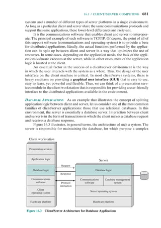
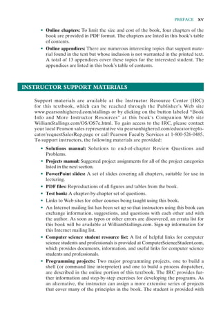
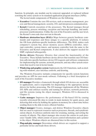
Figure 1.15 Performance of a Simple Two-Level
Memory](https://image.slidesharecdn.com/williamstallingsoperatingsystemsinter-230528124001-c4cbce35/85/William_Stallings_Operating_SystemsInter-pdf-48-320.jpg)


![1.7 / DIRECT MEMORY ACCESS 31
block size increases, more useful data are brought into the cache. The hit ratio will
begin to decrease, however, as the block becomes even bigger and the probability of
using the newly fetched data becomes less than the probability of reusing the data
that have to be moved out of the cache to make room for the new block.
When a new block of data is read into the cache, the mapping function deter-
mines which cache location the block will occupy. Two constraints affect the design
of the mapping function. First, when one block is read in, another may have to be
replaced. We would like to do this in such a way as to minimize the probability that
we will replace a block that will be needed in the near future. The more flexible the
mapping function, the more scope we have to design a replacement algorithm to
maximize the hit ratio. Second, the more flexible the mapping function, the more
complex is the circuitry required to search the cache to determine if a given block
is in the cache.
The replacement algorithm chooses, within the constraints of the mapping
function, which block to replace when a new block is to be loaded into the cache and
the cache already has all slots filled with other blocks. We would like to replace the
block that is least likely to be needed again in the near future. Although it is impos-
sible to identify such a block, a reasonably effective strategy is to replace the block
that has been in the cache longest with no reference to it. This policy is referred to
as the least-recently-used (LRU) algorithm. Hardware mechanisms are needed to
identify the least-recently-used block.
If the contents of a block in the cache are altered, then it is necessary to write it
back to main memory before replacing it. The write policy dictates when the mem-
ory write operation takes place. At one extreme, the writing can occur every time
that the block is updated. At the other extreme, the writing occurs only when the
block is replaced. The latter policy minimizes memory write operations but leaves
main memory in an obsolete state. This can interfere with multiple-processor opera-
tion and with direct memory access by I/O hardware modules.
Finally, it is now commonplace to have multiple levels of cache, labeled L1
(cache closest to the processor), L2, and in many cases a third level L3. A discus-
sion of the performance benefits of multiple cache levels is beyond our scope; see
[STAL10] for a discussion.
1.7 DIRECT MEMORY ACCESS
Three techniques are possible for I/O operations: programmed I/O, interrupt-driven
I/O, and direct memory access (DMA). Before discussing DMA, we briefly define
the other two techniques; see Appendix C for more detail.
When the processor is executing a program and encounters an instruction
relating to I/O, it executes that instruction by issuing a command to the appro-
priate I/O module. In the case of programmed I/O, the I/O module performs the
requested action and then sets the appropriate bits in the I/O status register but
takes no further action to alert the processor. In particular, it does not interrupt the
processor. Thus, after the I/O instruction is invoked, the processor must take some
active role in determining when the I/O instruction is completed. For this purpose,](https://image.slidesharecdn.com/williamstallingsoperatingsystemsinter-230528124001-c4cbce35/85/William_Stallings_Operating_SystemsInter-pdf-53-320.jpg)


![1.8 / MULTIPROCESSOR AND MULTICORE ORGANIZATION 35
also be possible for processors to exchange signals directly. The memory is often
organized so that multiple simultaneous accesses to separate blocks of memory are
possible.
In modern computers, processors generally have at least one level of cache
memory that is private to the processor. This use of cache introduces some new
design considerations. Because each local cache contains an image of a portion of
main memory, if a word is altered in one cache, it could conceivably invalidate a
word in another cache. To prevent this, the other processors must be alerted that an
update has taken place. This problem is known as the cache coherence problem and
is typically addressed in hardware rather than by the OS.6
Multicore Computers
A multicore computer, also known as a chip multiprocessor, combines two or more
processors (called cores) on a single piece of silicon (called a die). Typically, each
core consists of all of the components of an independent processor, such as registers,
ALU, pipeline hardware, and control unit, plus L1 instruction and data caches. In
addition to the multiple cores, contemporary multicore chips also include L2 cache
and, in some cases, L3 cache.
The motivation for the development of multicore computers can be summed
up as follows. For decades, microprocessor systems have experienced a steady, usu-
ally exponential, increase in performance. This is partly due to hardware trends,
such as an increase in clock frequency and the ability to put cache memory closer
to the processor because of the increasing miniaturization of microcomputer
components. Performance has also been improved by the increased complexity of
processor design to exploit parallelism in instruction execution and memory access.
In brief, designers have come up against practical limits in the ability to achieve
greater performance by means of more complex processors. Designers have found
that the best way to improve performance to take advantage of advances in hard-
ware is to put multiple processors and a substantial amount of cache memory on a
single chip. A detailed discussion of the rationale for this trend is beyond our scope,
but is summarized in Appendix C.
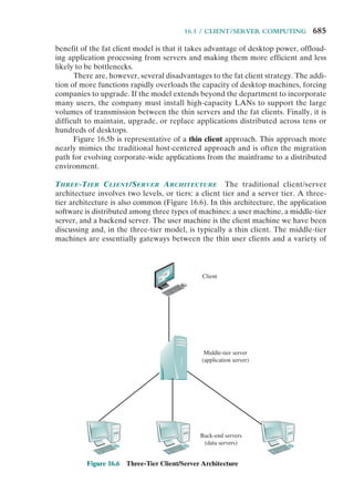
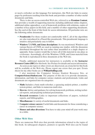
An example of a multicore system is the Intel Core i7, which includes four x86
processors, each with a dedicated L2 cache, and with a shared L3 cache (Figure 1.20).
One mechanism Intel uses to make its caches more effective is prefetching, in which
the hardware examines memory access patterns and attempts to fill the caches spec-
ulatively with data that’s likely to be requested soon.
The Core i7 chip supports two forms of external communications to other
chips. The DDR3 memory controller brings the memory controller for the DDR
(double data rate) main memory onto the chip. The interface supports three chan-
nels that are 8 bytes wide for a total bus width of 192 bits, for an aggregate data
rate of up to 32 GB/s. With the memory controller on the chip, the Front Side Bus
is eliminated. The QuickPath Interconnect (QPI) is a point-to-point link electri-
cal interconnect specification. It enables high-speed communications among con-
nected processor chips. The QPI link operates at 6.4 GT/s (transfers per second).
6
A description of hardware-based cache coherency schemes is provided in [STAL10].](https://image.slidesharecdn.com/williamstallingsoperatingsystemsinter-230528124001-c4cbce35/85/William_Stallings_Operating_SystemsInter-pdf-57-320.jpg)
![36 CHAPTER 1 / COMPUTER SYSTEM OVERVIEW
At 16 bits per transfer, that adds up to 12.8 GB/s; and since QPI links involve dedi-
cated bidirectional pairs, the total bandwidth is 25.6 GB/s.
1.9 RECOMMENDED READING AND WEB SITES
[STAL10] covers the topics of this chapter in detail. In addition, there are many other
texts on computer organization and architecture. Among the more worthwhile texts
are the following. [PATT09] is a comprehensive survey; [HENN07], by the same
authors, is a more advanced text that emphasizes quantitative aspects of design.
[DENN05] looks at the history of the development and application of the
locality principle, making for fascinating reading.
Core 0
32 kB I&D
L1 caches
256 kB
L2 cache
Core 1
32 kB I&D
L1 caches
256 kB
L2 cache
Core 2
3 × 8B @ 1.33 GT/s
32 kB I&D
L1 caches
256 kB
L2 cache
Core 3
32 kB I&D
L1 caches
256 kB
L2 cache
8 MB
L3 cache
DDR3 memory
controllers
Quickpath
interconnect
4 × 20b @ 6.4 GT/s
Figure 1.20 Intel Core i7 Block Diagram
Recommended Web sites:
• WWW Computer Architecture Home Page: A comprehensive index to information
relevant to computer architecture researchers, including architecture groups and proj-
ects, technical organizations, literature, employment, and commercial information
• CPU Info Center: Information on specific processors, including technical papers, prod-
uct information, and latest announcements
DENN05 Denning, P. “The Locality Principle.” Communications of the ACM, July 2005.
HENN07 Hennessy, J., and Patterson, D. Computer Architecture: A Quantitative
Approach. San Mateo, CA: Morgan Kaufmann, 2007.
PATT09 Patterson, D., and Hennessy, J. Computer Organization and Design: The
Hardware/Software Interface. San Mateo, CA: Morgan Kaufmann, 2009.
STAL10 Stallings, W. Computer Organization and Architecture, 8th ed. Upper Saddle
River, NJ: Prentice Hall, 2010.](https://image.slidesharecdn.com/williamstallingsoperatingsystemsinter-230528124001-c4cbce35/85/William_Stallings_Operating_SystemsInter-pdf-58-320.jpg)


![APPENDIX 1A / PERFORMANCE CHARACTERISTICS OF TWO-LEVEL MEMORIES 39
Assume that one processor cycle equals one bus cycle. Now suppose that very large
blocks of data are to be transferred between M and D.
a. If programmed I/O is used and each one-word I/O transfer requires the CPU to
execute two instructions, estimate the maximum I/O data transfer rate, in words
per second, possible through D.
b. Estimate the same rate if DMA transfer is used.
1.10. Consider the following code:
for (i ⫽ 0; i ⬍ 20; i++)
for (j ⫽ 0; j ⬍ 10; j++)
a[i] ⫽ a[i] * j
a. Give one example of the spatial locality in the code.
b. Give one example of the temporal locality in the code.
1.11. Generalize Equations (1.1) and (1.2) in Appendix 1A to n-level memory hierarchies.
1.12. Consider a memory system with the following parameters:
Tc ⫽ 100 ns Cc ⫽ 0.01 cents/bit
Tm ⫽ 1,200 ns Cm ⫽ 0.001 cents/bit
a. What is the cost of 1 MByte of main memory?
b. What is the cost of 1 MByte of main memory using cache memory technology?
c. If the effective access time is 10% greater than the cache access time, what is the
hit ratio H?
1.13. A computer has a cache, main memory, and a disk used for virtual memory. If a refer-
enced word is in the cache, 20 ns are required to access it. If it is in main memory but
not in the cache, 60 ns are needed to load it into the cache (this includes the time to
originally check the cache), and then the reference is started again. If the word is not
in main memory, 12 ms are required to fetch the word from disk, followed by 60 ns to
copy it to the cache, and then the reference is started again. The cache hit ratio is 0.9
and the main-memory hit ratio is 0.6.What is the average time in ns required to access
a referenced word on this system?
1.14. Suppose a stack is to be used by the processor to manage procedure calls and returns.
Can the program counter be eliminated by using the top of the stack as a program
counter?
APPENDIX 1A PERFORMANCE CHARACTERISTICS
OF TWO-LEVEL MEMORIES
In this chapter, reference is made to a cache that acts as a buffer between main
memory and processor, creating a two-level internal memory. This two-level archi-
tecture exploits a property known as locality to provide improved performance over
a comparable one-level memory.
The main memory cache mechanism is part of the computer architecture,
implemented in hardware and typically invisible to the OS. Accordingly, this
mechanism is not pursued in this book. However, there are two other instances
of a two-level memory approach that also exploit the property of locality and that
are, at least partially, implemented in the OS: virtual memory and the disk cache
(Table 1.2). These two topics are explored in Chapters 8 and 11, respectively. In this
appendix, we look at some of the performance characteristics of two-level memo-
ries that are common to all three approaches.](https://image.slidesharecdn.com/williamstallingsoperatingsystemsinter-230528124001-c4cbce35/85/William_Stallings_Operating_SystemsInter-pdf-61-320.jpg)
![40 CHAPTER 1 / COMPUTER SYSTEM OVERVIEW
Table 1.2 Characteristics of Two-Level Memories
Main Memory
Cache
Virtual Memory
(Paging) Disk Cache
Typical access time ratios 5 : 1 106
: 1 106
: 1
Memory management
system
Implemented by
special hardware
Combination of hardware
and system software
System software
Typical block size 4 to 128 bytes 64 to 4096 bytes 64 to 4096 bytes
Access of processor to
second level
Direct access Indirect access Indirect access
Locality
The basis for the performance advantage of a two-level memory is the principle of
locality, referred to in Section 1.5.This principle states that memory references tend
to cluster. Over a long period of time, the clusters in use change; but over a short
period of time, the processor is primarily working with fixed clusters of memory
references.
Intuitively, the principle of locality makes sense. Consider the following line
of reasoning:
1. Except for branch and call instructions, which constitute only a small fraction
of all program instructions, program execution is sequential. Hence, in most
cases, the next instruction to be fetched immediately follows the last instruc-
tion fetched.
2. It is rare to have a long uninterrupted sequence of procedure calls followed
by the corresponding sequence of returns. Rather, a program remains con-
fined to a rather narrow window of procedure-invocation depth. Thus, over
a short period of time references to instructions tend to be localized to a few
procedures.
3. Most iterative constructs consist of a relatively small number of instructions
repeated many times. For the duration of the iteration, computation is there-
fore confined to a small contiguous portion of a program.
4. In many programs, much of the computation involves processing data struc-
tures, such as arrays or sequences of records. In many cases, successive
references to these data structures will be to closely located data items.
This line of reasoning has been confirmed in many studies. With reference to
point (1), a variety of studies have analyzed the behavior of high-level language
programs. Table 1.3 includes key results, measuring the appearance of various
statement types during execution, from the following studies. The earliest study of
programming language behavior, performed by Knuth [KNUT71], examined a col-
lection of FORTRAN programs used as student exercises. Tanenbaum [TANE78]
published measurements collected from over 300 procedures used in OS programs
and written in a language that supports structured programming (SAL). Patterson
and Sequin [PATT82] analyzed a set of measurements taken from compilers
and programs for typesetting, computer-aided design (CAD), sorting, and file](https://image.slidesharecdn.com/williamstallingsoperatingsystemsinter-230528124001-c4cbce35/85/William_Stallings_Operating_SystemsInter-pdf-62-320.jpg)
![APPENDIX 1A / PERFORMANCE CHARACTERISTICS OF TWO-LEVEL MEMORIES 41
comparison. The programming languages C and Pascal were studied. Huck
[HUCK83] analyzed four programs intended to represent a mix of general-purpose
scientific computing, including fast Fourier transform and the integration of systems
of differential equations. There is good agreement in the results of this mixture of
languages and applications that branching and call instructions represent only a
fraction of statements executed during the lifetime of a program. Thus, these
studies confirm assertion (1), from the preceding list.
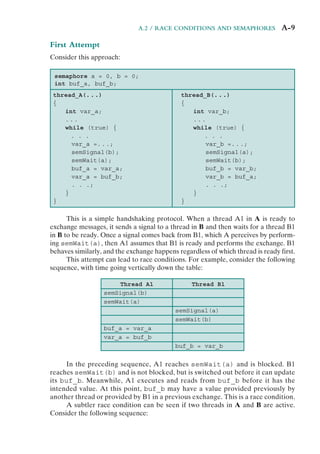
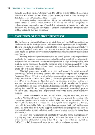
With respect to assertion (2), studies reported in [PATT85] provide confirma-
tion. This is illustrated in Figure 1.21, which shows call-return behavior. Each call is
represented by the line moving down and to the right, and each return by the line
moving up and to the right. In the figure, a window with depth equal to 5 is defined.
Only a sequence of calls and returns with a net movement of 6 in either direction
causes the window to move. As can be seen, the executing program can remain
within a stationary window for long periods of time. A study by the same analysts of
C and Pascal programs showed that a window of depth 8 would only need to shift on
less than 1% of the calls or returns [TAMI83].
Table 1.3 Relative Dynamic Frequency of High-Level Language Operations
Study [HUCK83] [KNUT71] [PATT82] [TANE78]
Language Pascal FORTRAN Pascal C SAL
Workload Scientific Student System System System
Assign 74 67 45 38 42
Loop 4 3 5 3 4
Call 1 3 15 12 12
IF 20 11 29 43 36
GOTO 2 9 — 3 —
Other — 7 6 1 6
w ⫽ 5
t ⫽ 33
Time
(in units of calls/returns)
Nesting
depth
Return
Call
Figure 1.21 Example Call-Return Behavior of a Program](https://image.slidesharecdn.com/williamstallingsoperatingsystemsinter-230528124001-c4cbce35/85/William_Stallings_Operating_SystemsInter-pdf-63-320.jpg)


![APPENDIX 1A / PERFORMANCE CHARACTERISTICS OF TWO-LEVEL MEMORIES 45
have shown that rather small cache sizes will yield a hit ratio above 0.75 regardless
of the size of main memory (e.g., [AGAR89], [PRZY88], [STRE83], and [SMIT82]).
A cache in the range of 1K to 128K words is generally adequate, whereas main
memory is now typically in the gigabyte range. When we consider virtual mem-
ory and disk cache, we will cite other studies that confirm the same phenomenon,
namely that a relatively small M1 yields a high value of hit ratio because of locality.
This brings us to the last question listed earlier: Does the relative size of the
two memories satisfy the cost requirement? The answer is clearly yes. If we need
only a relatively small upper-level memory to achieve good performance, then the
average cost per bit of the two levels of memory will approach that of the cheaper
lower-level memory.
No locality
Moderate
locality
Strong
locality
Hit
ratio
Relative memory size (S1/S2)
0.0
0.0
0.2
0.4
0.6
0.8
1.0
0.2 0.4 0.6 0.8 1.0
Figure 1.24 Hit Ratio as a Function of Relative Memory Size](https://image.slidesharecdn.com/williamstallingsoperatingsystemsinter-230528124001-c4cbce35/85/William_Stallings_Operating_SystemsInter-pdf-67-320.jpg)


![52 CHAPTER 2 / OPERATING SYSTEM OVERVIEW
the use of graphics terminals and page-mode terminals instead of line-at-a-
time scroll mode terminals affects OS design. For example, a graphics terminal
typically allows the user to view several applications at the same time through
“windows” on the screen. This requires more sophisticated support in the OS.
• New services: In response to user demand or in response to the needs of sys-
tem managers, the OS expands to offer new services. For example, if it is found
to be difficult to maintain good performance for users with existing tools, new
measurement and control tools may be added to the OS.
• Fixes: Any OS has faults. These are discovered over the course of time and
fixes are made. Of course, the fix may introduce new faults.
The need to change an OS regularly places certain requirements on its design.
An obvious statement is that the system should be modular in construction, with
clearly defined interfaces between the modules, and that it should be well docu-
mented. For large programs, such as the typical contemporary OS, what might be
referred to as straightforward modularization is inadequate [DENN80a]. That is,
much more must be done than simply partitioning a program into modules. We
return to this topic later in this chapter.
2.2 THE EVOLUTION OF OPERATING SYSTEMS
In attempting to understand the key requirements for an OS and the significance
of the major features of a contemporary OS, it is useful to consider how operating
systems have evolved over the years.
Serial Processing
With the earliest computers, from the late 1940s to the mid-1950s, the programmer
interacted directly with the computer hardware; there was no OS. These computers
were run from a console consisting of display lights, toggle switches, some form of
input device, and a printer. Programs in machine code were loaded via the input
device (e.g., a card reader). If an error halted the program, the error condition was
indicated by the lights. If the program proceeded to a normal completion, the out-
put appeared on the printer.
These early systems presented two main problems:
• Scheduling: Most installations used a hardcopy sign-up sheet to reserve com-
puter time. Typically, a user could sign up for a block of time in multiples of a
half hour or so. A user might sign up for an hour and finish in 45 minutes; this
would result in wasted computer processing time. On the other hand, the user
might run into problems, not finish in the allotted time, and be forced to stop
before resolving the problem.
• Setup time: A single program, called a job, could involve loading the com-
piler plus the high-level language program (source program) into memory,
saving the compiled program (object program) and then loading and linking
together the object program and common functions. Each of these steps could](https://image.slidesharecdn.com/williamstallingsoperatingsystemsinter-230528124001-c4cbce35/85/William_Stallings_Operating_SystemsInter-pdf-74-320.jpg)
![2.2 / THE EVOLUTION OF OPERATING SYSTEMS 53
involve mounting or dismounting tapes or setting up card decks. If an error
occurred, the hapless user typically had to go back to the beginning of the
setup sequence. Thus, a considerable amount of time was spent just in setting
up the program to run.
This mode of operation could be termed serial processing, reflecting the fact
that users have access to the computer in series. Over time, various system software
tools were developed to attempt to make serial processing more efficient. These
include libraries of common functions, linkers, loaders, debuggers, and I/O driver
routines that were available as common software for all users.
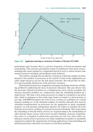
Simple Batch Systems
Early computers were very expensive, and therefore it was important to maxi-
mize processor utilization. The wasted time due to scheduling and setup time was
unacceptable.
To improve utilization, the concept of a batch OS was developed. It appears
that the first batch OS (and the first OS of any kind) was developed in the mid-1950s
by General Motors for use on an IBM 701 [WEIZ81]. The concept was subsequently
refined and implemented on the IBM 704 by a number of IBM customers. By the
early 1960s, a number of vendors had developed batch operating systems for their
computer systems. IBSYS, the IBM OS for the 7090/7094 computers, is particularly
notable because of its widespread influence on other systems.
The central idea behind the simple batch-processing scheme is the use of a
piece of software known as the monitor. With this type of OS, the user no longer has
direct access to the processor. Instead, the user submits the job on cards or tape to a
computer operator, who batches the jobs together sequentially and places the entire
batch on an input device, for use by the monitor. Each program is constructed to
branch back to the monitor when it completes processing, at which point the moni-
tor automatically begins loading the next program.
To understand how this scheme works, let us look at it from two points of
view: that of the monitor and that of the processor.
• Monitor point of view: The monitor controls the sequence of events. For this
to be so, much of the monitor must always be in main memory and available
for execution (Figure 2.3). That portion is referred to as the resident monitor.
The rest of the monitor consists of utilities and common functions that are
loaded as subroutines to the user program at the beginning of any job that
requires them. The monitor reads in jobs one at a time from the input device
(typically a card reader or magnetic tape drive). As it is read in, the current job
is placed in the user program area, and control is passed to this job. When the
job is completed, it returns control to the monitor, which immediately reads
in the next job. The results of each job are sent to an output device, such as a
printer, for delivery to the user.
• Processor point of view: At a certain point, the processor is executing instruc-
tions from the portion of main memory containing the monitor. These
instructions cause the next job to be read into another portion of main](https://image.slidesharecdn.com/williamstallingsoperatingsystemsinter-230528124001-c4cbce35/85/William_Stallings_Operating_SystemsInter-pdf-75-320.jpg)


![60 CHAPTER 2 / OPERATING SYSTEM OVERVIEW
Today, the requirement for an interactive computing facility can be, and often
is, met by the use of a dedicated personal computer or workstation. That option was
not available in the 1960s, when most computers were big and costly. Instead, time
sharing was developed.
Just as multiprogramming allows the processor to handle multiple batch jobs
at a time, multiprogramming can also be used to handle multiple interactive jobs. In
this latter case, the technique is referred to as time sharing, because processor time is
shared among multiple users. In a time-sharing system, multiple users simultaneously
access the system through terminals, with the OS interleaving the execution of each
user program in a short burst or quantum of computation. Thus, if there are n users
actively requesting service at one time, each user will only see on the average 1/n
of the effective computer capacity, not counting OS overhead. However, given the
relatively slow human reaction time, the response time on a properly designed system
should be similar to that on a dedicated computer.
Both batch processing and time sharing use multiprogramming. The key
differences are listed in Table 2.3.
One of the first time-sharing operating systems to be developed was the
Compatible Time-Sharing System (CTSS) [CORB62], developed at MIT by a
group known as Project MAC (Machine-Aided Cognition, or Multiple-Access
Computers). The system was first developed for the IBM 709 in 1961 and later
transferred to an IBM 7094.
Compared to later systems, CTSS is primitive. The system ran on a computer
with 32,000 36-bit words of main memory, with the resident monitor consuming 5000
of that. When control was to be assigned to an interactive user, the user’s program
and data were loaded into the remaining 27,000 words of main memory. A pro-
gram was always loaded to start at the location of the 5000th word; this simplified
both the monitor and memory management. A system clock generated interrupts
at a rate of approximately one every 0.2 seconds. At each clock interrupt, the OS
regained control and could assign the processor to another user. This technique is
known as time slicing. Thus, at regular time intervals, the current user would be
preempted and another user loaded in. To preserve the old user program status for
later resumption, the old user programs and data were written out to disk before the
new user programs and data were read in. Subsequently, the old user program code
and data were restored in main memory when that program was next given a turn.
To minimize disk traffic, user memory was only written out when the incoming
program would overwrite it. This principle is illustrated in Figure 2.7. Assume that
there are four interactive users with the following memory requirements, in words:
• JOB1: 15,000
• JOB2: 20,000
Table 2.3 Batch Multiprogramming versus Time Sharing
Batch Multiprogramming Time Sharing
Principal objective Maximize processor use Minimize response time
Source of directives to
operating system
Job control language commands
provided with the job
Commands entered at the
terminal](https://image.slidesharecdn.com/williamstallingsoperatingsystemsinter-230528124001-c4cbce35/85/William_Stallings_Operating_SystemsInter-pdf-82-320.jpg)

![62 CHAPTER 2 / OPERATING SYSTEM OVERVIEW
to a particular file. The contention for resources, such as printers and mass storage
devices, must be handled. These and other problems, with possible solutions, will be
encountered throughout this text.
2.3 MAJOR ACHIEVEMENTS
Operating systems are among the most complex pieces of software ever devel-
oped. This reflects the challenge of trying to meet the difficult and in some cases
competing objectives of convenience, efficiency, and ability to evolve. [DENN80a]
proposes that there have been four major theoretical advances in the development
of operating systems:
• Processes
• Memory management
• Information protection and security
• Scheduling and resource management
Each advance is characterized by principles, or abstractions, developed to
meet difficult practical problems. Taken together, these five areas span many of
the key design and implementation issues of modern operating systems. The brief
review of these five areas in this section serves as an overview of much of the rest
of the text.
The Process
Central to the design of operating systems is the concept of process. This term was
first used by the designers of Multics in the 1960s [DALE68]. It is a somewhat
more general term than job. Many definitions have been given for the term process,
including
• A program in execution
• An instance of a program running on a computer
• The entity that can be assigned to and executed on a processor
• A unit of activity characterized by a single sequential thread of execution, a
current state, and an associated set of system resources
This concept should become clearer as we proceed.
Three major lines of computer system development created problems in timing
and synchronization that contributed to the development of the concept of the
process: multiprogramming batch operation, time sharing, and real-time transaction
systems. As we have seen, multiprogramming was designed to keep the processor
and I/O devices, including storage devices, simultaneously busy to achieve maxi-
mum efficiency. The key mechanism is this: In response to signals indicating the
completion of I/O transactions, the processor is switched among the various pro-
grams residing in main memory.](https://image.slidesharecdn.com/williamstallingsoperatingsystemsinter-230528124001-c4cbce35/85/William_Stallings_Operating_SystemsInter-pdf-84-320.jpg)
![2.3 / MAJOR ACHIEVEMENTS 63
A second line of development was general-purpose time sharing. Here, the
key design objective is to be responsive to the needs of the individual user and yet,
for cost reasons, be able to support many users simultaneously. These goals are
compatible because of the relatively slow reaction time of the user. For example,
if a typical user needs an average of 2 seconds of processing time per minute, then
close to 30 such users should be able to share the same system without noticeable
interference. Of course, OS overhead must be factored into such calculations.
A third important line of development has been real-time transaction process-
ing systems. In this case, a number of users are entering queries or updates against a
database. An example is an airline reservation system. The key difference between
the transaction processing system and the time-sharing system is that the former
is limited to one or a few applications, whereas users of a time-sharing system can
engage in program development, job execution, and the use of various applications.
In both cases, system response time is paramount.
The principal tool available to system programmers in developing the early
multiprogramming and multiuser interactive systems was the interrupt. The activity
of any job could be suspended by the occurrence of a defined event, such as an I/O
completion. The processor would save some sort of context (e.g., program coun-
ter and other registers) and branch to an interrupt-handling routine, which would
determine the nature of the interrupt, process the interrupt, and then resume user
processing with the interrupted job or some other job.
The design of the system software to coordinate these various activities turned
out to be remarkably difficult. With many jobs in progress at any one time, each of
which involved numerous steps to be performed in sequence, it became impossible
to analyze all of the possible combinations of sequences of events. In the absence of
some systematic means of coordination and cooperation among activities, program-
mers resorted to ad hoc methods based on their understanding of the environment
that the OS had to control. These efforts were vulnerable to subtle programming
errors whose effects could be observed only when certain relatively rare sequences
of actions occurred. These errors were difficult to diagnose because they needed to
be distinguished from application software errors and hardware errors. Even when
the error was detected, it was difficult to determine the cause, because the precise
conditions under which the errors appeared were very hard to reproduce. In general
terms, there are four main causes of such errors [DENN80a]:
• Improper synchronization: It is often the case that a routine must be sus-
pended awaiting an event elsewhere in the system. For example, a program
that initiates an I/O read must wait until the data are available in a buffer
before proceeding. In such cases, a signal from some other routine is required.
Improper design of the signaling mechanism can result in signals being lost or
duplicate signals being received.
• Failed mutual exclusion: It is often the case that more than one user or pro-
gram will attempt to make use of a shared resource at the same time. For
example, two users may attempt to edit the same file at the same time. If
these accesses are not controlled, an error can occur. There must be some
sort of mutual exclusion mechanism that permits only one routine at a time
to perform an update against the file. The implementation of such mutual](https://image.slidesharecdn.com/williamstallingsoperatingsystemsinter-230528124001-c4cbce35/85/William_Stallings_Operating_SystemsInter-pdf-85-320.jpg)


![74 CHAPTER 2 / OPERATING SYSTEM OVERVIEW
2.5 VIRTUAL MACHINES
Virtual Machines and Virtualizing
Traditionally, applications have run directly on an OS on a PC or a server. Each PC
or server would run only one OS at a time. Thus, the vendor had to rewrite parts
of its applications for each OS/platform they would run on. An effective strategy
for dealing with this problem is known as virtualization. Virtualization technology
enables a single PC or server to simultaneously run multiple operating systems or
multiple sessions of a single OS. A machine with virtualization can host numerous
applications, including those that run on different operating systems, on a single
platform. In essence, the host operating system can support a number of virtual
machines (VM), each of which has the characteristics of a particular OS and, in some
versions of virtualization, the characteristics of a particular hardware platform.
The VM approach is becoming a common way for businesses and individuals
to deal with legacy applications and to optimize their hardware usage by maximizing
the number of kinds of applications that a single computer can handle [GEER09].
Commercial VM offerings by companies such as VMware and Microsoft are widely
used, with millions of copies having been sold. In addition to their use in server
environments, these VM technologies also are used in desktop environments to run
multiple operating systems, typically Windows and Linux.
The specific architecture of the VM approach varies among vendors.
Figure 2.13 shows a typical arrangement. The virtual machine monitor (VMM), or
hypervisor, runs on top of (or is incorporated into) the host OS. The VMM sup-
ports VMs, which are emulated hardware devices. Each VM runs a separate OS.
The VMM handles each operating system’s communications with the processor,
the storage medium, and the network. To execute programs, the VMM hands off
the processor control to a virtual OS on a VM. Most VMs use virtualized network
Shared hardware
Host operating system
Virtual machine monitor
Virtual
machine 1
Virtual
machine 2
Virtual
machine n
Applications
and
processes
Applications
and
processes
Applications
and
processes
Figure 2.13 Virtual Memory Concept](https://image.slidesharecdn.com/williamstallingsoperatingsystemsinter-230528124001-c4cbce35/85/William_Stallings_Operating_SystemsInter-pdf-96-320.jpg)
![2.5 / VIRTUAL MACHINES 75
connections to communicate with one another, when such communication is needed.
Key to the success of this approach is that the VMM provides a layer between soft-
ware environments and the underlying hardware and host OS that is programma-
ble, transparent to the software above it, and makes efficient use of the hardware
below it.
Virtual Machine Architecture2
Recall from Section 2.1 (see Figure 2.1) the discussion of the application program-
ming interface, the application binary interface, and the instruction set archi-
tecture. Let us use these interface concepts to clarify the meaning of machine in
the term virtual machine. Consider a process executing a compiled application
program. From the perspective of the process, the machine on which it executes
consists of the virtual memory space assigned to the process, the processor reg-
isters it may use, the user-level machine instructions it may execute, and the OS
system calls it may invoke for I/O. Thus the ABI defines the machine as seen by
a process.
From the perspective of an application, the machine characteristics are speci-
fied by high-level language capabilities, and OS and system library calls. Thus, the
API defines the machine for an application.
For the operating system, the machine hardware defines the system that
supports the operation of the OS and the numerous processes that execute con-
currently. These processes share a file system and other I/O resources. The system
allocates real memory and I/O resources to the processes and allows the processes
to interact with their resources. From the OS perspective, therefore, it is the ISA
that provides the interface between the system and machine.
With these considerations in mind, we can consider two architectural
approaches to implementing virtual machines: process VMs and system VMs.
PROCESS VIRTUAL MACHINE In essence, a process VM presents an ABI to an
application process, translates a set of OS and user-level instructions composing one
platform to those of another (Figure 2.14a). A process VM is a virtual platform for
executing a single process. As such, the process VM is created when the process is
created and terminated when the process is terminated.
In order to provide cross-platform portability, a common implementation of
the process VM architecture is as part of an overall HLL application environment.
The resulting ABI does not correspond to any specific machine. Instead, the ABI
specification is designed to easily support a given HLL or set of HLLs and to be eas-
ily portable to a variety of ISAs. The HLL VM includes a front-end compiler that
generates a virtual binary code for execution or interpretation. This code can then
be executed on any machine that has the process VM implemented.
Two widely used examples of this approach are the Java VM architecture and
the Microsoft Common Language Infrastructure, which is the foundation of the
.NET framework.
2
Much of the discussion that follows is based on [SMIT05].](https://image.slidesharecdn.com/williamstallingsoperatingsystemsinter-230528124001-c4cbce35/85/William_Stallings_Operating_SystemsInter-pdf-97-320.jpg)


![2.6 / OS DESIGN CONSIDERATIONS FOR MULTIPROCESSOR AND MULTICORE 79
GCD does not help the developer decide how to break up a task or application into
separate concurrent parts. But once a developer has identified something that can
be split off into a separate task, GCD makes it as easy and noninvasive as possible
to actually do so.
In essence, GCD is a thread pool mechanism, in which the OS maps tasks onto
threads representing an available degree of concurrency (plus threads for block-
ing on I/O). Windows also has a thread pool mechanism (since 2000), and thread
pools have been heavily used in server applications for years. What is new in GCD
is the extension to programming languages to allow anonymous functions (called
blocks) as a way of specifying tasks. GCD is hence not a major evolutionary step.
Nevertheless, it is a new and valuable tool for exploiting the available parallelism of
a multicore system.
One of Apple’s slogans for GCD is “islands of serialization in a sea of concurrency.”
That captures the practical reality of adding more concurrency to run-of-the-mill
desktop applications. Those islands are what isolate developers from the thorny
problems of simultaneous data access, deadlock, and other pitfalls of multithreading.
Developers are encouraged to identify functions of their applications that would be
better executed off the main thread, even if they are made up of several sequential or
otherwise partially interdependent tasks. GCD makes it easy to break off the entire
unit of work while maintaining the existing order and dependencies between subtasks.
In later chapters, we look at some of the details of GCD.
VIRTUAL MACHINE APPROACH An alternative approach is to recognize that
with the ever-increasing number of cores on a chip, the attempt to multiprogram
individual cores to support multiple applications may be a misplaced use of
resources [JACK10]. If instead, we allow one or more cores to be dedicated to a
particular process and then leave the processor alone to devote its efforts to that
process, we avoid much of the overhead of task switching and scheduling decisions.
The multicore OS could then act as a hypervisor that makes a high-level decision
to allocate cores to applications but does little in the way of resource allocation
beyond that.
The reasoning behind this approach is as follows. In the early days of com-
puting, one program was run on a single processor. With multiprogramming,
each application is given the illusion that it is running on a dedicated processor.
Multiprogramming is based on the concept of a process, which is an abstraction of
an execution environment. To manage processes, the OS requires protected space,
free from user and program interference. For this purpose, the distinction between
kernel mode and user mode was developed. In effect, kernel mode and user mode
abstracted the processor into two processors. With all these virtual processors, how-
ever, come struggles over who gets the attention of the real processor. The overhead
of switching between all these processors starts to grow to the point where respon-
siveness suffers, especially when multiple cores are introduced. But with many-core
systems, we can consider dropping the distinction between kernel and user mode.
In this approach, the OS acts more like a hypervisor. The programs themselves take
on many of the duties of resource management. The OS assigns an application a
processor and some memory, and the program itself, using metadata generated by
the compiler, would best know how to use these resources.](https://image.slidesharecdn.com/williamstallingsoperatingsystemsinter-230528124001-c4cbce35/85/William_Stallings_Operating_SystemsInter-pdf-101-320.jpg)


![82 CHAPTER 2 / OPERATING SYSTEM OVERVIEW
Architecture
Figure 2.15 illustrates the overall structure of Windows 7; all releases of Windows
based on NT have essentially the same structure at this level of detail.
As with virtually all operating systems, Windows separates application-oriented
software from the core OS software. The latter, which includes the Executive, the
Kernel, device drivers, and the hardware abstraction layer, runs in kernel mode.
Kernel mode software has access to system data and to the hardware. The remaining
software, running in user mode, has limited access to system data.
OPERATING SYSTEM ORGANIZATION Windows has a highly modular architecture.
Each system function is managed by just one component of the OS. The rest of the
OS and all applications access that function through the responsible component using
standard interfaces. Key system data can only be accessed through the appropriate
User mode
Kernel mode
Session
manager
System
threads
System service dispatcher
Winlogon
Lsass
Lsass = local security authentication server
POSIX = portable operating system interface
GDI = graphics device interface
DLL = dynamic link libraries
Colored area indicates Executive
System support
processes
Service processes
Applications
Environment
subsystems
Service control
manager
Spooler
Winmgmt.exe
SVChost.exe
User
application
Subsytem DLLs Win32
Ntdll.dll
Windows
explorer
Task manager
(Kernel-mode callable interfaces)
Win32 USER,
GDI
Graphics
drivers
Hardware abstraction layer (HAL)
File
system
cache
Object
manager
Plug-and-play
manager
Power
manager
Security
reference
monitor
Virtual
memory
Processes
and
threads
Configuration
manager
(registry)
Local
procedure
call
POSIX
Device
and file
system
drivers
I/O manager
Kernel
Services.exe
Figure 2.15 Windows and Windows Vista Architecture [RUSS11]](https://image.slidesharecdn.com/williamstallingsoperatingsystemsinter-230528124001-c4cbce35/85/William_Stallings_Operating_SystemsInter-pdf-104-320.jpg)


![86 CHAPTER 2 / OPERATING SYSTEM OVERVIEW
• It provides a suitable base for distributed computing. Typically, distributed
computing makes use of a client/server model, with remote procedure calls
implemented using distributed client and server modules and the exchange of
messages between clients and servers. With Windows, a local server can pass
a message on to a remote server for processing on behalf of local client appli-
cations. Clients need not know whether a request is being serviced locally or
remotely. Indeed, whether a request is serviced locally or remotely can change
dynamically based on current load conditions and on dynamic configuration
changes.
Threads and SMP
Two important characteristics of Windows are its support for threads and for
symmetric multiprocessing (SMP), both of which were introduced in Section 2.4.
[RUSS11] lists the following features of Windows that support threads and SMP:
• OS routines can run on any available processor, and different routines can
execute simultaneously on different processors.
• Windows supports the use of multiple threads of execution within a single
process. Multiple threads within the same process may execute on different
processors simultaneously.
• Server processes may use multiple threads to process requests from more than
one client simultaneously.
• Windows provides mechanisms for sharing data and resources between proc-
esses and flexible interprocess communication capabilities.
Windows Objects
Though the core of Windows is written in C, the design principles followed draw
heavily on the concepts of object-oriented design. This approach facilitates the shar-
ing of resources and data among processes and the protection of resources from
unauthorized access. Among the key object-oriented concepts used by Windows are
the following:
• Encapsulation: An object consists of one or more items of data, called
attributes, and one or more procedures that may be performed on those data,
called services. The only way to access the data in an object is by invoking one
of the object’s services. Thus, the data in the object can easily be protected
from unauthorized use and from incorrect use (e.g., trying to execute a non-
executable piece of data).
• Object class and instance: An object class is a template that lists the attributes
and services of an object and defines certain object characteristics. The OS can
create specific instances of an object class as needed. For example, there is a
single process object class and one process object for every currently active
process. This approach simplifies object creation and management.
• Inheritance: Although the implementation is hand coded, the Executive uses
inheritance to extend object classes by adding new features. Every Executive](https://image.slidesharecdn.com/williamstallingsoperatingsystemsinter-230528124001-c4cbce35/85/William_Stallings_Operating_SystemsInter-pdf-108-320.jpg)


![90 CHAPTER 2 / OPERATING SYSTEM OVERVIEW
2.8 TRADITIONAL UNIX SYSTEMS
History
The history of UNIX is an oft-told tale and will not be repeated in great detail here.
Instead, we provide a brief summary.
UNIX was initially developed at Bell Labs and became operational on a
PDP-7 in 1970. Some of the people involved at Bell Labs had also participated in
the time-sharing work being done at MIT’s Project MAC. That project led to the
development of first CTSS and then Multics. Although it is common to say that
the original UNIX was a scaled-down version of Multics, the developers of UNIX
actually claimed to be more influenced by CTSS [RITC78]. Nevertheless, UNIX
incorporated many ideas from Multics.
Work on UNIX at Bell Labs, and later elsewhere, produced a series of versions
of UNIX. The first notable milestone was porting the UNIX system from the PDP-7 to
the PDP-11. This was the first hint that UNIX would be an OS for all computers. The
next important milestone was the rewriting of UNIX in the programming language
C. This was an unheard-of strategy at the time. It was generally felt that something as
complex as an OS, which must deal with time-critical events, had to be written exclu-
sively in assembly language. Reasons for this attitude include the following:
• Memory (both RAM and secondary store) was small and expensive by today’s
standards, so effective use was important. This included various techniques for
overlaying memory with different code and data segments, and self-modifying
code.
• Even though compilers had been available since the 1950s, the computer
industry was generally skeptical of the quality of automatically generated
code. With resource capacity small, efficient code, both in terms of time and
space, was essential.
• Processor and bus speeds were relatively slow, so saving clock cycles could
make a substantial difference in execution time.
The C implementation demonstrated the advantages of using a high-level
language for most if not all of the system code. Today, virtually all UNIX imple-
mentations are written in C.
These early versions of UNIX were popular within Bell Labs. In 1974, the
UNIX system was described in a technical journal for the first time [RITC74]. This
spurred great interest in the system. Licenses for UNIX were provided to commer-
cial institutions as well as universities. The first widely available version outside Bell
Labs was Version 6, in 1976. The follow-on Version 7, released in 1978, is the ances-
tor of most modern UNIX systems. The most important of the non-AT&T systems
to be developed was done at the University of California at Berkeley, called UNIX
BSD (Berkeley Software Distribution), running first on PDP and then VAX com-
puters. AT&T continued to develop and refine the system. By 1982, Bell Labs had
combined several AT&T variants of UNIX into a single system, marketed com-
mercially as UNIX System III. A number of features was later added to the OS to
produce UNIX System V.](https://image.slidesharecdn.com/williamstallingsoperatingsystemsinter-230528124001-c4cbce35/85/William_Stallings_Operating_SystemsInter-pdf-112-320.jpg)
![2.8 / TRADITIONAL UNIX SYSTEMS 91
Description
Figure 2.16 provides a general description of the classic UNIX architecture. The
underlying hardware is surrounded by the OS software. The OS is often called the
system kernel, or simply the kernel, to emphasize its isolation from the user and appli-
cations. It is the UNIX kernel that we will be concerned with in our use of UNIX as
an example in this book. UNIX also comes equipped with a number of user services
and interfaces that are considered part of the system. These can be grouped into
the shell, other interface software, and the components of the C compiler (compiler,
assembler, loader). The layer outside of this consists of user applications and the user
interface to the C compiler.
A closer look at the kernel is provided in Figure 2.17. User programs can
invoke OS services either directly or through library programs. The system call
interface is the boundary with the user and allows higher-level software to gain
access to specific kernel functions. At the other end, the OS contains primitive rou-
tines that interact directly with the hardware. Between these two interfaces, the
system is divided into two main parts, one concerned with process control and the
other concerned with file management and I/O. The process control subsystem is
responsible for memory management, the scheduling and dispatching of processes,
and the synchronization and interprocess communication of processes. The file sys-
tem exchanges data between memory and external devices either as a stream of
characters or in blocks. To achieve this, a variety of device drivers are used. For
block-oriented transfers, a disk cache approach is used: A system buffer in main
memory is interposed between the user address space and the external device.
The description in this subsection has dealt with what might be termed
traditional UNIX systems; [VAHA96] uses this term to refer to System V Release
3 (SVR3), 4.3BSD, and earlier versions. The following general statements may be
Hardware
Kernel
System call
interface
UNIX commands
and libraries
User-written
applications
Figure 2.16 General UNIX Architecture](https://image.slidesharecdn.com/williamstallingsoperatingsystemsinter-230528124001-c4cbce35/85/William_Stallings_Operating_SystemsInter-pdf-113-320.jpg)


![2.10 / LINUX 95
GNU Public License (GPL) is the FSF seal of approval. Torvalds used GNU tools
in developing his kernel, which he then released under the GPL. Thus, the Linux
distributions that you see today are the product of FSF’s GNU project, Torvald’s
individual effort, and the efforts of many collaborators all over the world.
In addition to its use by many individual programmers, Linux has now made
significant penetration into the corporate world. This is not only because of the
free software, but also because of the quality of the Linux kernel. Many talented
programmers have contributed to the current version, resulting in a technically
impressive product. Moreover, Linux is highly modular and easily configured. This
makes it easy to squeeze optimal performance from a variety of hardware platforms.
Plus, with the source code available, vendors can tweak applications and utilities to
meet specific requirements. Throughout this book, we will provide details of Linux
kernel internals based on the most recent version, Linux 2.6.
Modular Structure
Most UNIX kernels are monolithic. Recall from earlier in this chapter that a mono-
lithic kernel is one that includes virtually all of the OS functionality in one large
block of code that runs as a single process with a single address space. All the func-
tional components of the kernel have access to all of its internal data structures
and routines. If changes are made to any portion of a typical monolithic OS, all the
modules and routines must be relinked and reinstalled and the system rebooted
before the changes can take effect. As a result, any modification, such as adding
a new device driver or file system function, is difficult. This problem is especially
acute for Linux, for which development is global and done by a loosely associated
group of independent programmers.
Although Linux does not use a microkernel approach, it achieves many of
the potential advantages of this approach by means of its particular modular archi-
tecture. Linux is structured as a collection of modules, a number of which can be
automatically loaded and unloaded on demand. These relatively independent blocks
are referred to as loadable modules [GOYE99]. In essence, a module is an object
file whose code can be linked to and unlinked from the kernel at runtime. Typically,
a module implements some specific function, such as a file system, a device driver,
or some other feature of the kernel’s upper layer. A module does not execute as its
own process or thread, although it can create kernel threads for various purposes
as necessary. Rather, a module is executed in kernel mode on behalf of the current
process.
Thus, although Linux may be considered monolithic, its modular structure
overcomes some of the difficulties in developing and evolving the kernel.
The Linux loadable modules have two important characteristics:
• Dynamic linking: A kernel module can be loaded and linked into the kernel
while the kernel is already in memory and executing. A module can also be
unlinked and removed from memory at any time.
• Stackable modules: The modules are arranged in a hierarchy. Individual
modules serve as libraries when they are referenced by client modules higher
up in the hierarchy, and as clients when they reference modules further down.](https://image.slidesharecdn.com/williamstallingsoperatingsystemsinter-230528124001-c4cbce35/85/William_Stallings_Operating_SystemsInter-pdf-117-320.jpg)
![96 CHAPTER 2 / OPERATING SYSTEM OVERVIEW
Dynamic linking [FRAN97] facilitates configuration and saves kernel memory.
In Linux, a user program or user can explicitly load and unload kernel modules
using the insmod and rmmod commands. The kernel itself monitors the need for
particular functions and can load and unload modules as needed. With stackable
modules, dependencies between modules can be defined. This has two benefits:
1. Code common to a set of similar modules (e.g., drivers for similar hardware)
can be moved into a single module, reducing replication.
2. The kernel can make sure that needed modules are present, refraining from
unloading a module on which other running modules depend, and loading any
additional required modules when a new module is loaded.
Figure 2.19 is an example that illustrates the structures used by Linux to
manage modules. The figure shows the list of kernel modules after only two modules
have been loaded: FAT and VFAT. Each module is defined by two tables, the mod-
ule table and the symbol table. The module table includes the following elements:
• *next: Pointer to the following module. All modules are organized into a
linked list. The list begins with a pseudomodule (not shown in Figure 2.19).
• *name: Pointer to module name
• size: Module size in memory pages
• usecount: Module usage counter. The counter is incremented when an opera-
tion involving the module’s functions is started and decremented when the
operation terminates.
FAT
*syms
*deps
*refs
ndeps
nysms
flags
usecount
size
*name
*next
value
*name
value
Symbol_table
*name
value
*name
value
*name
value
*name
value
*name
VFAT
Module
Symbol_table
*syms
*deps
*refs
ndeps
nysms
flags
usecount
size
*name
*next
Module
Figure 2.19 Example List of Linux Kernel Modules](https://image.slidesharecdn.com/williamstallingsoperatingsystemsinter-230528124001-c4cbce35/85/William_Stallings_Operating_SystemsInter-pdf-118-320.jpg)
![2.10 / LINUX 97
• flags: Module flags
• nsyms: Number of exported symbols
• ndeps: Number of referenced modules
• *syms: Pointer to this module’s symbol table.
• *deps: Pointer to list of modules that are referenced by this module.
• *refs: Pointer to list of modules that use this module.
The symbol table defines those symbols controlled by this module that are
used elsewhere.
Figure 2.19 shows that the VFAT module was loaded after the FAT module
and that the VFAT module is dependent on the FAT module.
Kernel Components
Figure 2.20, taken from [MOSB02], shows the main components of the Linux kernel
as implemented on an IA-64 architecture (e.g., Intel Itanium). The figure shows
several processes running on top of the kernel. Each box indicates a separate pro-
cess, while each squiggly line with an arrowhead represents a thread of execution.4
The kernel itself consists of an interacting collection of components, with arrows
Signals System calls
Processes
& scheduler
Virtual
memory
Physical
memory
System
memory
Processes
Hardware
User
level
Kernel
CPU Terminal Disk
Traps &
faults
Char device
drivers
Block device
drivers
Network
device drivers
File
systems
Network
protocols
Interrupts
Network interface
controller
Figure 2.20 Linux Kernel Components
4
In Linux, there is no distinction between the concepts of processes and threads. However, multiple
threads in Linux can be grouped together in such a way that, effectively, you can have a single process
comprising multiple threads.These matters are discussed in Chapter 4.](https://image.slidesharecdn.com/williamstallingsoperatingsystemsinter-230528124001-c4cbce35/85/William_Stallings_Operating_SystemsInter-pdf-119-320.jpg)


![100 CHAPTER 2 / OPERATING SYSTEM OVERVIEW
• File systems: Provides a global, hierarchical namespace for files, directories,
and other file related objects and provides file system functions.
• Network protocols: Supports the Sockets interface to users for the TCP/IP
protocol suite.
• Character device drivers: Manages devices that require the kernel to send or
receive data one byte at a time, such as terminals, modems, and printers.
• Block device drivers: Manages devices that read and write data in blocks, such
as various forms of secondary memory (magnetic disks, CD-ROMs, etc.).
• Network device drivers: Manages network interface cards and communica-
tions ports that connect to network devices, such as bridges and routers.
• Traps and faults: Handles traps and faults generated by the processor, such as
a memory fault.
• Physical memory: Manages the pool of page frames in real memory and allo-
cates pages for virtual memory.
• Interrupts: Handles interrupts from peripheral devices.
2.11 LINUXVSERVERVIRTUAL MACHINE ARCHITECTURE
Linux VServer is an open-source, fast, lightweight approach to implement-
ing virtual machines on a Linux server [SOLT07, LIGN05]. Only a single copy
of the Linux kernel is involved. VServer consists of a relatively modest modifi-
cation to the kernel plus a small set of OS userland5
tools. The VServer Linux
kernel supports a number of separate virtual servers. The kernel manages all sys-
tem resources and tasks, including process scheduling, memory, disk space, and
processor time. This is closer in concept to the process VM rather than the system
VM of Figure 2.14.
Each virtual server is isolated from the others using Linux kernel capabilities.
This provides security and makes it easy to set up multiple virtual machines on a
single platform. The isolation involves four elements: chroot, chcontext, chbind, and
capabilities.
The chroot command is a UNIX or Linux command to make the root directory
(/) become something other than its default for the lifetime of the current process.
It can only be run by privileged users and is used to give a process (commonly a net-
work server such as FTP or HTTP) access to a restricted portion of the file system.
This command provides file system isolation. All commands executed by the virtual
server can only affect files that start with the defined root for that server.
The chcontext Linux utility allocates a new security context and executes
commands in that context. The usual or hosted security context is the context 0.
This context has the same privileges as the root user (UID 0): This context can
see and kill other tasks in the other contexts. Context number 1 is used to view
5
The term userland refers to all application software that runs in user space rather than kernel space. OS
userland usually refers to the various programs and libraries that the operating system uses to interact
with the kernel: software that performs input/output, manipulates file system objects, etc.](https://image.slidesharecdn.com/williamstallingsoperatingsystemsinter-230528124001-c4cbce35/85/William_Stallings_Operating_SystemsInter-pdf-122-320.jpg)
![2.12 / RECOMMENDED READING AND WEB SITES 101
other contexts but cannot affect them. All other contexts provide complete isola-
tion: Processes from one context can neither see nor interact with processes from
another context. This provides the ability to run similar contexts on the same com-
puter without any interaction possible at the application level. Thus, each virtual
server has its own execution context that provides process isolation.
The chbind utility executes a command, and locks the resulting process and
its children into using a specific IP address. Once called, all packets sent out by this
virtual server through the system’s network interface are assigned the sending IP
address derived from the argument given to chbind. This system call provides net-
work isolation: Each virtual server uses a separate and distinct IP address. Incoming
traffic intended for one virtual server cannot be accessed by other virtual servers.
Finally, each virtual server is assigned a set of capabilities. The concept of
capabilities, as used in Linux, refers to a partitioning of the privileges available to
a root user, such as the ability to read files or to trace processes owned by another
user. Thus, each virtual server can be assigned a limited subset of the root user’s
privileges. This provides root isolation. VServer can also set resource limits, such as
limits to the amount of virtual memory a process may use.
Figure 2.21, based on [SOLT07], shows the general architecture of Linux
VServer. VServer provides a shared, virtualized OS image, consisting of a root file
system, and a shared set of system libraries and kernel services. Each VM can be
booted, shut down, and rebooted independently. Figure 2.21 shows three group-
ings of software running on the computer system. The hosting platform includes the
shared OS image and a privileged host VM, whose function is to monitor and man-
age the other VMs. The virtual platform creates virtual machines and is the view of
the system seen by the applications running on the individual VMs.
2.12 RECOMMENDED READING AND WEB SITES
[BRIN01] is an excellent collection of papers covering major advances in OS design
over the years. [SWAI07] is a provocative and interesting short article on the future
of operating systems.
VM admin.
Remote admin.
Core services
Server
applications
Standard OS image
Hosting
platform
Virtual
platform
Server
applications
/proc
/home
/usr
/dev
/proc
/home
/usr
/dev
/proc
/home
/usr
/dev
VMhost VM1 VMn
Figure 2.21 Linux VServer Architecture](https://image.slidesharecdn.com/williamstallingsoperatingsystemsinter-230528124001-c4cbce35/85/William_Stallings_Operating_SystemsInter-pdf-123-320.jpg)
![102 CHAPTER 2 / OPERATING SYSTEM OVERVIEW
[MUKH96] provides a good discussion of OS design issues for SMPs.
[CHAP97] contains five articles on recent design directions for multiprocessor
operating systems. Worthwhile discussions of the principles of microkernel design
are contained in [LIED95] and [LIED96]; the latter focuses on performance
issues.
[LI10] and [SMIT05] provide good treatments of virtual machines.
An excellent treatment of UNIX internals, which provides a comparative
analysis of a number of variants, is [VAHA96]. For UNIX SVR4, [GOOD94]
provides a definitive treatment, with ample technical detail. For the popular open-
source FreeBSD, [MCKU05] is highly recommended. [MCDO07] provides a good
treatment of Solaris internals. Good treatments of Linux internals are [LOVE10]
and [MAUE08].
Although there are countless books on various versions of Windows, there
is remarkably little material available on Windows internals. The book to read is
[RUSS11].
BRIN01 Brinch Hansen, P. Classic Operating Systems: From Batch Processing to
Distributed Systems. New York: Springer-Verlag, 2001.
CHAP97 Chapin, S., and Maccabe, A., eds. “Multiprocessor Operating Systems:
Harnessing the Power.” special issue of IEEE Concurrency, April–June 1997.
GOOD94 Goodheart, B., and Cox, J. The Magic Garden Explained: The Internals of
UNIX System V Release 4. Englewood Cliffs, NJ: Prentice Hall, 1994.
LOVE10 Love, R. Linux Kernel Development. Upper Saddle River, NJ: Addison-
Wesley, 2010.
LI10 Li, Y.; Li, W.; and Jiang, C. “A Survey of Virtual Machine Systems: Current
Technology and Future Trends.” Proceedings, Third International Symposium on
Electronic Commerce and Security, 2010.
LIED95 Liedtke, J. “On μ-Kernel Construction.” Proceedings of the Fifteenth ACM
Symposium on Operating Systems Principles, December 1995.
LIED96 Liedtke, J. “Toward Real Microkernels.” Communications of the ACM,
September 1996.
MAUE08 Mauerer, W. Professional Linux Kernel Architecture. New York: Wiley, 2008.
MCDO07 McDougall, R., and Mauro, J. Solaris Internals: Solaris 10 and OpenSolaris
Kernel Architecture. Palo Alto, CA: Sun Microsystems Press, 2007.
MCKU05 McKusick, M., and Neville-Neil, J. The Design and Implementation of the
FreeBSD Operating System. Reading, MA: Addison-Wesley, 2005.
MUKH96 Mukherjee, B., and Karsten, S. “Operating Systems for Parallel Machines.”
In Parallel Computers: Theory and Practice. Edited by T. Casavant, P. Tvrkik, and
F. Plasil. Los Alamitos, CA: IEEE Computer Society Press, 1996.
RUSS11 Russinovich, M.; Solomon, D.; and Ionescu, A. Windows Internals: Covering
Windows 7 and Windows Server 2008 R2. Redmond, WA: Microsoft Press, 2011.
SMIT05 Smith, J., and Nair, R. “The Architecture of Virtual Machines.” Computer,
May 2005.
SWAI07 Swaine, M. “Wither Operating Systems?” Dr. Dobb’s Journal, March 2007.
VAHA96 Vahalia, U. UNIX Internals: The New Frontiers. Upper Saddle River, NJ:
Prentice Hall, 1996.](https://image.slidesharecdn.com/williamstallingsoperatingsystemsinter-230528124001-c4cbce35/85/William_Stallings_Operating_SystemsInter-pdf-124-320.jpg)


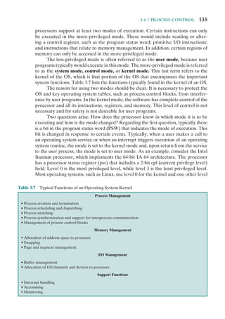


![3.6 / SECURITY ISSUES 143
level and be interleaved with other processes under dispatcher control. Finally,
implementing the OS as a set of processes is useful in a multiprocessor or multicom-
puter environment, in which some of the operating system services can be shipped
out to dedicated processors, improving performance.
3.6 SECURITY ISSUES
An OS associates a set of privileges with each process. These privileges dictate what
resources the process may access, including regions of memory, files, privileged sys-
tem instructions, and so on. Typically, a process that executes on behalf of a user
has the privileges that the OS recognizes for that user. A system or utility process
may have privileges assigned at configuration time.
On a typical system, the highest level of privilege is referred to as administra-
tor, supervisor, or root access.11
Root access provides access to all the functions and
services of the operating system. With root access, a process has complete control of
the system and can add or change programs and files, monitor other processes, send
and receive network traffic, and alter privileges.
A key security issue in the design of any OS is to prevent, or at least detect,
attempts by a user or a piece of malicious software (malware) from gaining unau-
thorized privileges on the system and, in particular, from gaining root access. In
this section, we briefly summarize the threats and countermeasures related to this
security issue. Part Seven provides more detail.
System Access Threats
System access threats fall into two general categories: intruders and malicious
software.
INTRUDERS One of the most common threats to security is the intruder (the other
is viruses), often referred to as a hacker or cracker. In an important early study of
intrusion, Anderson [ANDE80] identified three classes of intruders:
• Masquerader: An individual who is not authorized to use the computer and
who penetrates a system’s access controls to exploit a legitimate user’s account
• Misfeasor: A legitimate user who accesses data, programs, or resources for
which such access is not authorized, or who is authorized for such access but
misuses his or her privileges
• Clandestine user: An individual who seizes supervisory control of the system
and uses this control to evade auditing and access controls or to suppress audit
collection
The masquerader is likely to be an outsider; the misfeasor generally is an insider;
and the clandestine user can be either an outsider or an insider.
Intruder attacks range from the benign to the serious. At the benign end of the
scale, there are many people who simply wish to explore internets and see what is
11
On UNIX systems, the administrator, or superuser, account is called root; hence the term root access.](https://image.slidesharecdn.com/williamstallingsoperatingsystemsinter-230528124001-c4cbce35/85/William_Stallings_Operating_SystemsInter-pdf-165-320.jpg)


![3.7 / UNIX SVR4 PROCESS MANAGEMENT 147
[BELL94] lists the following design goals for a firewall:
1. All traffic from inside to outside, and vice versa, must pass through the fire-
wall. This is achieved by physically blocking all access to the local network
except via the firewall. Various configurations are possible, as explained later
in this chapter.
2. Only authorized traffic, as defined by the local security policy, will be allowed
to pass. Various types of firewalls are used, which implement various types of
security policies.
3. The firewall itself is immune to penetration. This implies the use of a hard-
ened system with a secured operating system. Trusted computer systems are
suitable for hosting a firewall and often required in government applications.
3.7 UNIX SVR4 PROCESS MANAGEMENT
UNIX System V makes use of a simple but powerful process facility that is highly
visible to the user. UNIX follows the model of Figure 3.15b, in which most of the OS
executes within the environment of a user process. UNIX uses two categories of pro-
cesses: system processes and user processes. System processes run in kernel mode and
execute operating system code to perform administrative and housekeeping func-
tions, such as allocation of memory and process swapping. User processes operate
in user mode to execute user programs and utilities and in kernel mode to execute
instructions that belong to the kernel. A user process enters kernel mode by issuing a
system call, when an exception (fault) is generated, or when an interrupt occurs.
Process States
A total of nine process states are recognized by the UNIX SVR4 operating system;
these are listed in Table 3.9 and a state transition diagram is shown in Figure 3.17
Table 3.9 UNIX Process States
User Running Executing in user mode.
Kernel Running Executing in kernel mode.
Ready to Run, in
Memory
Ready to run as soon as the kernel schedules it.
Asleep in Memory Unable to execute until an event occurs; process is in main memory (a blocked state).
Ready to Run,
Swapped
Process is ready to run, but the swapper must swap the process into main memory
before the kernel can schedule it to execute.
Sleeping, Swapped The process is awaiting an event and has been swapped to secondary storage (a
blocked state).
Preempted Process is returning from kernel to user mode, but the kernel preempts it and does a
process switch to schedule another process.
Created Process is newly created and not yet ready to run.
Zombie Process no longer exists, but it leaves a record for its parent process to collect.](https://image.slidesharecdn.com/williamstallingsoperatingsystemsinter-230528124001-c4cbce35/85/William_Stallings_Operating_SystemsInter-pdf-169-320.jpg)
![148 CHAPTER 3 / PROCESS DESCRIPTION AND CONTROL
(based on figure in [BACH86]). This figure is similar to Figure 3.9b, with the two
UNIX sleeping states corresponding to the two blocked states. The differences are
as follows:
• UNIX employs two Running states to indicate whether the process is execut-
ing in user mode or kernel mode.
• A distinction is made between the two states: (Ready to Run, in Memory) and
(Preempted). These are essentially the same state, as indicated by the dotted
line joining them. The distinction is made to emphasize the way in which the
preempted state is entered. When a process is running in kernel mode (as a
result of a supervisor call, clock interrupt, or I/O interrupt), there will come
a time when the kernel has completed its work and is ready to return control
to the user program. At this point, the kernel may decide to preempt the cur-
rent process in favor of one that is ready and of higher priority. In that case,
the current process moves to the preempted state. However, for purposes of
dispatching, those processes in the Preempted state and those in the (Ready to
Run, in Memory) state form one queue.
Preemption can only occur when a process is about to move from kernel mode
to user mode. While a process is running in kernel mode, it may not be preempted.
This makes UNIX unsuitable for real-time processing. Chapter 10 discusses the
requirements for real-time processing.
Fork
Not enough memory
(swapping system only)
Enough
memory
Swap in
Swap out
Swap out
Wakeup
Wakeup
Sleep
Return
Preempt
Return
to User
System call,
interrupt
Exit
Reschedule
process
Interrupt,
interrupt return
Preempted
Created
Ready to run
swapped
Ready to run
in memory
Kernel
running
Zombie
Asleep in
memory
Sleep,
swapped
User
running
Figure 3.17 UNIX Process State Transition Diagram](https://image.slidesharecdn.com/williamstallingsoperatingsystemsinter-230528124001-c4cbce35/85/William_Stallings_Operating_SystemsInter-pdf-170-320.jpg)


![3.7 / UNIX SVR4 PROCESS MANAGEMENT 151
the dynamic portion of the system-level context. This stack is used when the process
is executing in kernel mode and contains the information that must be saved and
restored as procedure calls and interrupts occur.
Process Control
Process creation in UNIX is made by means of the kernel system call, fork( ). When
a process issues a fork request, the OS performs the following functions [BACH86]:
1. It allocates a slot in the process table for the new process.
2. It assigns a unique process ID to the child process.
3. It makes a copy of the process image of the parent, with the exception of any
shared memory.
4. It increments counters for any files owned by the parent, to reflect that an
additional process now also owns those files.
5. It assigns the child process to the Ready to Run state.
6. It returns the ID number of the child to the parent process, and a 0 value to
the child process.
All of this work is accomplished in kernel mode in the parent process. When
the kernel has completed these functions it can do one of the following, as part of
the dispatcher routine:
• Stay in the parent process. Control returns to user mode at the point of the
fork call of the parent.
Table 3.12 UNIX U Area
Process table
pointer
Indicates entry that corresponds to the U area.
User identifiers Real and effective user IDs. Used to determine user privileges.
Timers Record time that the process (and its descendants) spent executing in user mode and in
kernel mode.
Signal-handler
array
For each type of signal defined in the system, indicates how the process will react to
receipt of that signal (exit, ignore, execute specified user function).
Control terminal Indicates login terminal for this process, if one exists.
Error field Records errors encountered during a system call.
Return value Contains the result of system calls.
I/O parameters Describe the amount of data to transfer, the address of the source (or target) data array
in user space, and file offsets for I/O.
File parameters Current directory and current root describe the file system environment of the process.
User file
descriptor table
Records the files the process has opened.
Limit fields Restrict the size of the process and the size of a file it can write.
Permission modes
fields
Mask mode settings on files the process creates.](https://image.slidesharecdn.com/williamstallingsoperatingsystemsinter-230528124001-c4cbce35/85/William_Stallings_Operating_SystemsInter-pdf-173-320.jpg)
![152 CHAPTER 3 / PROCESS DESCRIPTION AND CONTROL
• Transfer control to the child process. The child process begins executing
at the same point in the code as the parent, namely at the return from the
fork call.
• Transfer control to another process. Both parent and child are left in the
Ready to Run state.
It is perhaps difficult to visualize this method of process creation because both
parent and child are executing the same passage of code. The difference is this:
When the return from the fork occurs, the return parameter is tested. If the value is
zero, then this is the child process, and a branch can be executed to the appropriate
user program to continue execution. If the value is nonzero, then this is the parent
process, and the main line of execution can continue.
3.8 SUMMARY
The most fundamental concept in a modern OS is the process. The principal func-
tion of the OS is to create, manage, and terminate processes. While processes are
active, the OS must see that each is allocated time for execution by the proces-
sor, coordinate their activities, manage conflicting demands, and allocate system
resources to processes.
To perform its process management functions, the OS maintains a description
of each process, or process image, which includes the address space within which the
process executes, and a process control block. The latter contains all of the informa-
tion that is required by the OS to manage the process, including its current state,
resources allocated to it, priority, and other relevant data.
During its lifetime, a process moves among a number of states. The most
important of these are Ready, Running, and Blocked. A ready process is one that
is not currently executing but that is ready to be executed as soon as the OS dis-
patches it. The running process is that process that is currently being executed by
the processor. In a multiple-processor system, more than one process can be in this
state. A blocked process is waiting for the completion of some event, such as an I/O
operation.
A running process is interrupted either by an interrupt, which is an event that
occurs outside the process and that is recognized by the processor, or by executing
a supervisor call to the OS. In either case, the processor performs a mode switch,
transferring control to an operating system routine. The OS, after it has completed
necessary work, may resume the interrupted process or switch to some other
process.
3.9 RECOMMENDED READING
Good descriptions of UNIX process management are found in [GOOD94] and
[GRAY97]. [NEHM75] is an interesting discussion of process states and the operat-
ing system primitives needed for process dispatching.](https://image.slidesharecdn.com/williamstallingsoperatingsystemsinter-230528124001-c4cbce35/85/William_Stallings_Operating_SystemsInter-pdf-174-320.jpg)


![3.10 / KEY TERMS, REVIEW QUESTIONS, AND PROBLEMS 155
The four modes are as follows:
• Kernel: Executes the kernel of the VMS operating system, which includes memory
management, interrupt handling, and I/O operations
• Executive: Executes many of the OS service calls, including file and record (disk
and tape) management routines
• Supervisor: Executes other OS services, such as responses to user commands
• User: Executes user programs, plus utilities such as compilers, editors, linkers, and
debuggers
A process executing in a less-privileged mode often needs to call a procedure that
executes in a more-privileged mode; for example, a user program requires an operat-
ing system service. This call is achieved by using a change-mode (CHM) instruction,
which causes an interrupt that transfers control to a routine at the new access mode.A
return is made by executing the REI (return from exception or interrupt) instruction.
a. A number of operating systems have two modes, kernel and user. What are the
advantages and disadvantages of providing four modes instead of two?
b. Can you make a case for even more than four modes?
3.8 TheVMS scheme discussed in the preceding problem is often referred to as a ring pro-
tection structure, as illustrated in Figure 3.18. Indeed, the simple kernel/user scheme,
as described in Section 3.3, is a two-ring structure. [SILB04] points out a problem with
this approach:
The main disadvantage of the ring (hierarchical) structure is that it does not
allow us to enforce the need-to-know principle. In particular, if an object must
Table 3.13 VAX/VMS Process States
Process State Process Condition
Currently Executing Running process.
Computable (resident) Ready and resident in main memory.
Computable (outswapped) Ready, but swapped out of main memory.
Page Fault Wait Process has referenced a page not in main memory and must wait for
the page to be read in.
Collided Page Wait Process has referenced a shared page that is the cause of an existing
page fault wait in another process, or a private page that is in the
process of being read in or written out.
Common Event Wait Waiting for shared event flag (event flags are single-bit interprocess
signaling mechanisms).
Free Page Wait Waiting for a free page in main memory to be added to the collection of
pages in main memory devoted to this process (the working set of the
process).
Hibernate Wait (resident) Process puts itself in a wait state.
Hibernate Wait (outswapped) Hibernating process is swapped out of main memory.
Local Event Wait (resident) Process in main memory and waiting for local event flag (usually I/O
completion).
Local Event Wait (outswapped) Process in local event wait is swapped out of main memory.
Suspended Wait (resident) Process is put into a wait state by another process.
Suspended Wait (outswapped) Suspended process is swapped out of main memory.
Resource Wait Process waiting for miscellaneous system resource.](https://image.slidesharecdn.com/williamstallingsoperatingsystemsinter-230528124001-c4cbce35/85/William_Stallings_Operating_SystemsInter-pdf-177-320.jpg)


![4.1 / PROCESSES AND THREADS 159
distinguish the two characteristics, the unit of dispatching is usually referred to
as a thread or lightweight process, while the unit of resource ownership is usually
referred to as a process or task.1
Multithreading
Multithreading refers to the ability of an OS to support multiple, concurrent paths
of execution within a single process. The traditional approach of a single thread of
execution per process, in which the concept of a thread is not recognized, is referred
to as a single-threaded approach. The two arrangements shown in the left half of
Figure 4.1 are single-threaded approaches. MS-DOS is an example of an OS that
supports a single user process and a single thread. Other operating systems, such
as some variants of UNIX, support multiple user processes but only support one
thread per process. The right half of Figure 4.1 depicts multithreaded approaches.
A Java run-time environment is an example of a system of one process with multi-
ple threads. Of interest in this section is the use of multiple processes, each of which
supports multiple threads. This approach is taken in Windows, Solaris, and many
modern versions of UNIX, among others. In this section we give a general description
1
Alas, even this degree of consistency is not maintained. In IBM’s mainframe operating systems, the con-
cepts of address space and task, respectively, correspond roughly to the concepts of process and thread
that we describe in this section. Also, in the literature, the term lightweight process is used as either (1)
equivalent to the term thread, (2) a particular type of thread known as a kernel-level thread, or (3) in the
case of Solaris, an entity that maps user-level threads to kernel-level threads.
One process
One thread
One process
Multiple threads
Multiple processes
One thread per process
= Instruction trace
Multiple processes
Multiple threads per process
Figure 4.1 Threads and Processes [ANDE97]](https://image.slidesharecdn.com/williamstallingsoperatingsystemsinter-230528124001-c4cbce35/85/William_Stallings_Operating_SystemsInter-pdf-181-320.jpg)

![4.1 / PROCESSES AND THREADS 161
block for each thread containing register values, priority, and other thread-related
state information.
Thus, all of the threads of a process share the state and resources of that
process. They reside in the same address space and have access to the same data.
When one thread alters an item of data in memory, other threads see the results if
and when they access that item. If one thread opens a file with read privileges, other
threads in the same process can also read from that file.
The key benefits of threads derive from the performance implications:
1. It takes far less time to create a new thread in an existing process than to
create a brand-new process. Studies done by the Mach developers show that
thread creation is ten times faster than process creation in UNIX [TEVA87].
2. It takes less time to terminate a thread than a process.
3. It takes less time to switch between two threads within the same process than
to switch between processes.
4. Threads enhance efficiency in communication between different executing
programs. In most operating systems, communication between independent
processes requires the intervention of the kernel to provide protection and the
mechanisms needed for communication. However, because threads within the
same process share memory and files, they can communicate with each other
without invoking the kernel.
Thus, if there is an application or function that should be implemented as a
set of related units of execution, it is far more efficient to do so as a collection of
threads rather than a collection of separate processes.
An example of an application that could make use of threads is a file server.
As each new file request comes in, a new thread can be spawned for the file manage-
ment program. Because a server will handle many requests, many threads will be
created and destroyed in a short period. If the server runs on a multiprocessor com-
puter, then multiple threads within the same process can be executing simultaneously
on different processors. Further, because processes or threads in a file server must
share file data and therefore coordinate their actions, it is faster to use threads and
shared memory than processes and message passing for this coordination.
The thread construct is also useful on a single processor to simplify the structure
of a program that is logically doing several different functions.
[LETW88] gives four examples of the uses of threads in a single-user multi-
processing system:
• Foreground and background work: For example, in a spreadsheet program,
one thread could display menus and read user input, while another thread
executes user commands and updates the spreadsheet. This arrangement often
increases the perceived speed of the application by allowing the program to
prompt for the next command before the previous command is complete.
• Asynchronous processing: Asynchronous elements in the program can be
implemented as threads. For example, as a protection against power failure,
one can design a word processor to write its random access memory (RAM)
buffer to disk once every minute. A thread can be created whose sole job is](https://image.slidesharecdn.com/williamstallingsoperatingsystemsinter-230528124001-c4cbce35/85/William_Stallings_Operating_SystemsInter-pdf-183-320.jpg)
![162 CHAPTER 4 / THREADS
periodic backup and that schedules itself directly with the OS; there is no need
for fancy code in the main program to provide for time checks or to coordinate
input and output.
• Speed of execution: A multithreaded process can compute one batch of data
while reading the next batch from a device. On a multiprocessor system, mul-
tiple threads from the same process may be able to execute simultaneously.
Thus, even though one thread may be blocked for an I/O operation to read in
a batch of data, another thread may be executing.
• Modular program structure: Programs that involve a variety of activities or a
variety of sources and destinations of input and output may be easier to design
and implement using threads.
In an OS that supports threads, scheduling and dispatching is done on a thread
basis; hence, most of the state information dealing with execution is maintained in
thread-level data structures. There are, however, several actions that affect all of the
threads in a process and that the OS must manage at the process level. For example,
suspension involves swapping the address space of one process out of main memory
to make room for the address space of another process. Because all threads in a
process share the same address space, all threads are suspended at the same time.
Similarly, termination of a process terminates all threads within that process.
Thread Functionality
Like processes, threads have execution states and may synchronize with one
another. We look at these two aspects of thread functionality in turn.
THREAD STATES As with processes, the key states for a thread are Running, Ready,
and Blocked. Generally, it does not make sense to associate suspend states with
threads because such states are process-level concepts. In particular, if a process is
swapped out, all of its threads are necessarily swapped out because they all share
the address space of the process.
There are four basic thread operations associated with a change in thread
state [ANDE04]:
• Spawn: Typically, when a new process is spawned, a thread for that process
is also spawned. Subsequently, a thread within a process may spawn another
thread within the same process, providing an instruction pointer and argu-
ments for the new thread. The new thread is provided with its own register
context and stack space and placed on the ready queue.
• Block: When a thread needs to wait for an event, it will block (saving its user
registers, program counter, and stack pointers). The processor may now
turn to the execution of another ready thread in the same or a different
process.
• Unblock: When the event for which a thread is blocked occurs, the thread is
moved to the Ready queue.
• Finish: When a thread completes, its register context and stacks are
deallocated.](https://image.slidesharecdn.com/williamstallingsoperatingsystemsinter-230528124001-c4cbce35/85/William_Stallings_Operating_SystemsInter-pdf-184-320.jpg)
![4.1 / PROCESSES AND THREADS 163
A significant issue is whether the blocking of a thread results in the blocking
of the entire process. In other words, if one thread in a process is blocked, does
this prevent the running of any other thread in the same process even if that other
thread is in a ready state? Clearly, some of the flexibility and power of threads is lost
if the one blocked thread blocks an entire process.
We return to this issue subsequently in our discussion of user-level versus
kernel-level threads, but for now let us consider the performance benefits of threads
that do not block an entire process. Figure 4.3 (based on one in [KLEI96]) shows a
program that performs two remote procedure calls (RPCs)2
to two different hosts
to obtain a combined result. In a single-threaded program, the results are obtained
in sequence, so the program has to wait for a response from each server in turn.
Rewriting the program to use a separate thread for each RPC results in a substantial
speedup. Note that if this program operates on a uniprocessor, the requests must be
generated sequentially and the results processed in sequence; however, the program
waits concurrently for the two replies.
2
An RPC is a technique by which two programs, which may execute on different machines, interact using
procedure call/return syntax and semantics. Both the called and calling program behave as if the partner
program were running on the same machine. RPCs are often used for client/server applications and are
discussed in Chapter 16.
(a) RPC using single thread
(b) RPC using one thread per server (on a uniprocessor)
Time
Process 1
Blocked, waiting for response to RPC
Blocked, waiting for processor, which is in use by Thread B
Running
Thread A (Process 1)
Thread B (Process 1)
Server Server
Server
Server
RPC
request
RPC
request
RPC
request
RPC
request
Figure 4.3 Remote Procedure Call (RPC) Using Threads](https://image.slidesharecdn.com/williamstallingsoperatingsystemsinter-230528124001-c4cbce35/85/William_Stallings_Operating_SystemsInter-pdf-185-320.jpg)
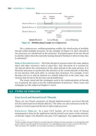


![4.2 / TYPES OF THREADS 169
Thus, on the face of it, while there is a significant speedup by using KLT mul-
tithreading compared to single-threaded processes, there is an additional signifi-
cant speedup by using ULTs. However, whether or not the additional speedup is
realized depends on the nature of the applications involved. If most of the thread
switches in an application require kernel mode access, then a ULT-based scheme
may not perform much better than a KLT-based scheme.
COMBINED APPROACHES Some operating systems provide a combined ULT/
KLT facility (Figure 4.5c). In a combined system, thread creation is done
completely in user space, as is the bulk of the scheduling and synchronization of
threads within an application. The multiple ULTs from a single application are
mapped onto some (smaller or equal) number of KLTs. The programmer may
adjust the number of KLTs for a particular application and processor to achieve
the best overall results.
In a combined approach, multiple threads within the same application can
run in parallel on multiple processors, and a blocking system call need not block
the entire process. If properly designed, this approach should combine the advan-
tages of the pure ULT and KLT approaches while minimizing the disadvantages.
Solaris is a good example of an OS using this combined approach. The current
Solaris version limits the ULT/KLT relationship to be one-to-one.
Other Arrangements
As we have said, the concepts of resource allocation and dispatching unit have
traditionally been embodied in the single concept of the process—that is, as a 1 : 1
relationship between threads and processes. Recently, there has been much inter-
est in providing for multiple threads within a single process, which is a many-to-
one relationship. However, as Table 4.2 shows, the other two combinations have
also been investigated, namely, a many-to-many relationship and a one-to-many
relationship.
MANY-TO-MANY RELATIONSHIP The idea of having a many-to-many relationship
between threads and processes has been explored in the experimental operating
system TRIX [PAZZ92, WARD80]. In TRIX, there are the concepts of domain
Table 4.2 Relationship between Threads and Processes
Threads: Processes Description Example Systems
1:1 Each thread of execution is a unique process with its
own address space and resources.
Traditional UNIX
implementations
M:1 A process defines an address space and dynamic
resource ownership. Multiple threads may be created
and executed within that process.
Windows NT, Solaris,
Linux, OS/2, OS/390,
MACH
1:M A thread may migrate from one process environment
to another. This allows a thread to be easily moved
among distinct systems.
Ra (Clouds),
Emerald
M:N Combines attributes of M:1 and 1:M cases. TRIX](https://image.slidesharecdn.com/williamstallingsoperatingsystemsinter-230528124001-c4cbce35/85/William_Stallings_Operating_SystemsInter-pdf-191-320.jpg)

![4.3 / MULTICORE AND MULTITHREADING 171
concept of a thread as primarily an entity that can move among address spaces.5
A
notable example of this research is the Clouds operating system, and especially its
kernel, known as Ra [DASG92]. Another example is the Emerald system [STEE95].
A thread in Clouds is a unit of activity from the user’s perspective. A process
is a virtual address space with an associated process control block. Upon creation,
a thread starts executing in a process by invoking an entry point to a program in
that process. Threads may move from one address space to another and actually
span computer boundaries (i.e., move from one computer to another). As a thread
moves, it must carry with it certain information, such as the controlling terminal,
global parameters, and scheduling guidance (e.g., priority).
The Clouds approach provides an effective way of insulating both users and
programmers from the details of the distributed environment. A user’s activity may
be represented as a single thread, and the movement of that thread among comput-
ers may be dictated by the OS for a variety of system-related reasons, such as the
need to access a remote resource, and load balancing.
4.3 MULTICORE AND MULTITHREADING
The use of a multicore system to support a single application with multiple threads,
such as might occur on a workstation, a video-game console, or a personal computer
running a processor-intense application, raises issues of performance and applica-
tion design. In this section, we first look at some of the performance implications
of a multithreaded application on a multicore system and then describe a specific
example of an application designed to exploit multicore capabilities.
Performance of Software on Multicore
The potential performance benefits of a multicore organization depend on the
ability to effectively exploit the parallel resources available to the application. Let
us focus first on a single application running on a multicore system. Amdahl’s law
(see Appendix E) states that:
Speedup =
time to execute program on a single processor
time to execute program on N parallel processors
=
1
(1 - f ) +
f
N
The law assumes a program in which a fraction (1 - f) of the execution time
involves code that is inherently serial and a fraction f that involves code that is infi-
nitely parallelizable with no scheduling overhead.
This law appears to make the prospect of a multicore organization attractive.
But as Figure 4.7a shows, even a small amount of serial code has a noticeable impact.
If only 10% of the code is inherently serial (f = 0.9), running the program on a
multicore system with eight processors yields a performance gain of only a factor
of 4.7. In addition, software typically incurs overhead as a result of communication
5
The movement of processes or threads among address spaces, or thread migration, on different machines
has become a hot topic in recent years. Chapter 18 explores this topic.](https://image.slidesharecdn.com/williamstallingsoperatingsystemsinter-230528124001-c4cbce35/85/William_Stallings_Operating_SystemsInter-pdf-193-320.jpg)
![172 CHAPTER 4 / THREADS
and distribution of work to multiple processors and cache coherence overhead. This
results in a curve where performance peaks and then begins to degrade because
of the increased burden of the overhead of using multiple processors. Figure 4.7b,
from [MCDO07], is a representative example.
However, software engineers have been addressing this problem and there are
numerous applications in which it is possible to effectively exploit a multicore sys-
tem. [MCDO07] reports on a set of database applications, in which great attention
Relative
speedup
0
2
4
6
8
2
1
Number of processors
(a) Speedup with 0%, 2%, 5%, and 10% sequential portions
3 4 5 6
0%
2%
5%
10%
7 8
Relative
speedup
10%
5%
15%
20%
0
0.5
1.0
1.5
2.0
2.5
2
1
Number of processors
(b) Speedup with overheads
3 4 5 6 7 8
Figure 4.7 Performance Effect of Multiple Cores](https://image.slidesharecdn.com/williamstallingsoperatingsystemsinter-230528124001-c4cbce35/85/William_Stallings_Operating_SystemsInter-pdf-194-320.jpg)
![4.3 / MULTICORE AND MULTITHREADING 173
was paid to reducing the serial fraction within hardware architectures, operating
systems, middleware, and the database application software. Figure 4.8 shows the
result. As this example shows, database management systems and database applica-
tions are one area in which multicore systems can be used effectively. Many kinds of
servers can also effectively use the parallel multicore organization, because servers
typically handle numerous relatively independent transactions in parallel.
In addition to general-purpose server software, a number of classes of applica-
tions benefit directly from the ability to scale throughput with the number of cores.
[MCDO06] lists the following examples:
• Multithreaded native applications: Multithreaded applications are charac-
terized by having a small number of highly threaded processes. Examples
of threaded applications include Lotus Domino or Siebel CRM (Customer
Relationship Manager).
• Multiprocess applications: Multiprocess applications are characterized by
the presence of many single-threaded processes. Examples of multiprocess
applications include the Oracle database, SAP, and PeopleSoft.
• Java applications: Java applications embrace threading in a fundamental way.
Not only does the Java language greatly facilitate multithreaded applications,
but the Java Virtual Machine is a multithreaded process that provides sched-
uling and memory management for Java applications. Java applications that
can benefit directly from multicore resources include application servers such
as Sun’s Java Application Server, BEA’s Weblogic, IBM’s Websphere, and
the open-source Tomcat application server. All applications that use a Java 2
Platform, Enterprise Edition (J2EE platform) application server can immedi-
ately benefit from multicore technology.
0
0
16
32
48
64
16 32
Number of CPUs
Scaling
48 64
p
e
r
f
e
c
t
s
c
a
l
i
n
g
Oracle DSS 4-way join
TMC data mining
DB2 DSS scan & aggs
Oracle ad hoc insurance OLTP
Figure 4.8 Scaling of Database Workloads on Multiple-Processor Hardware](https://image.slidesharecdn.com/williamstallingsoperatingsystemsinter-230528124001-c4cbce35/85/William_Stallings_Operating_SystemsInter-pdf-195-320.jpg)
![174 CHAPTER 4 / THREADS
• Multiinstance applications: Even if an individual application does not scale
to take advantage of a large number of threads, it is still possible to gain from
multicore architecture by running multiple instances of the application in
parallel. If multiple application instances require some degree of isolation,
virtualization technology (for the hardware of the operating system) can be
used to provide each of them with its own separate and secure environment.
Application Example: Valve Game Software
Valve is an entertainment and technology company that has developed a number
of popular games, as well as the Source engine, one of the most widely played game
engines available. Source is an animation engine used by Valve for its games and
licensed for other game developers.
In recent years, Valve has reprogrammed the Source engine software to use
multithreading to exploit the power of multicore processor chips from Intel and
AMD [REIM06]. The revised Source engine code provides more powerful support
for Valve games such as Half Life 2.
From Valve’s perspective, threading granularity options are defined as follows
[HARR06]:
• Coarse threading: Individual modules, called systems, are assigned to individ-
ual processors. In the Source engine case, this would mean putting rendering
on one processor, AI (artificial intelligence) on another, physics on another,
and so on. This is straightforward. In essence, each major module is single
threaded and the principal coordination involves synchronizing all the threads
with a timeline thread.
• Fine-grained threading: Many similar or identical tasks are spread across mul-
tiple processors. For example, a loop that iterates over an array of data can be
split up into a number of smaller parallel loops in individual threads that can
be scheduled in parallel.
• Hybrid threading: This involves the selective use of fine-grained threading for
some systems and single threading for other systems.
Valve found that through coarse threading, it could achieve up to twice the
performance across two processors compared to executing on a single processor.
But this performance gain could only be achieved with contrived cases. For real-
world gameplay, the improvement was on the order of a factor of 1.2. Valve also
found that effective use of fine-grained threading was difficult. The time per work
unit can be variable, and managing the timeline of outcomes and consequences
involved complex programming.
Valve found that a hybrid threading approach was the most promising and
would scale the best, as multicore systems with 8 or 16 processors became available.
Valve identified systems that operate very effectively being permanently assigned
to a single processor. An example is sound mixing, which has little user interaction,
is not constrained by the frame configuration of windows, and works on its own set
of data. Other modules, such as scene rendering, can be organized into a number
of threads so that the module can execute on a single processor but achieve greater
performance as it is spread out over more and more processors.](https://image.slidesharecdn.com/williamstallingsoperatingsystemsinter-230528124001-c4cbce35/85/William_Stallings_Operating_SystemsInter-pdf-196-320.jpg)
![4.3 / MULTICORE AND MULTITHREADING 175
Figure 4.9 illustrates the thread structure for the rendering module. In this hier-
archical structure, higher-level threads spawn lower-level threads as needed. The
rendering module relies on a critical part of the Source engine, the world list, which
is a database representation of the visual elements in the game’s world. The first task
is to determine what are the areas of the world that need to be rendered. The next
task is to determine what objects are in the scene as viewed from multiple angles.
Then comes the processor-intensive work. The rendering module has to work out
the rendering of each object from multiple points of view, such as the player’s view,
the view of TV monitors, and the point of view of reflections in water.
Some of the key elements of the threading strategy for the rendering module
are listed in [LEON07] and include the following:
• Construct scene-rendering lists for multiple scenes in parallel (e.g., the world
and its reflection in water).
• Overlap graphics simulation.
• Compute character bone transformations for all characters in all scenes in
parallel.
• Allow multiple threads to draw in parallel.
The designers found that simply locking key databases, such as the world list, for
a thread was too inefficient. Over 95% of the time, a thread is trying to read from a data
set, and only 5% of the time at most is spent in writing to a data set. Thus, a concurrency
mechanism known as the single-writer-multiple-readers model works effectively.
Render
Skybox Main view
Scene list
For each object
Particles
Sim and draw
Bone setup
Draw
Character
Etc.
Monitor Etc.
Figure 4.9 Hybrid Threading for Rendering Module](https://image.slidesharecdn.com/williamstallingsoperatingsystemsinter-230528124001-c4cbce35/85/William_Stallings_Operating_SystemsInter-pdf-197-320.jpg)
![176 CHAPTER 4 / THREADS
4.4 WINDOWS 7 THREAD AND SMP MANAGEMENT
Windows process design is driven by the need to provide support for a variety of OS
environments. Processes supported by different OS environments differ in a number
of ways, including the following:
• How processes are named
• Whether threads are provided within processes
• How processes are represented
• How process resources are protected
• What mechanisms are used for interprocess communication and synchronization
• How processes are related to each other
Accordingly, the native process structures and services provided by the
Windows Kernel are relatively simple and general purpose, allowing each OS
subsystem to emulate a particular process structure and functionality. Important
characteristics of Windows processes are the following:
• Windows processes are implemented as objects.
• A process can be created as new process, or as a copy of an existing process.
• An executable process may contain one or more threads.
• Both process and thread objects have built-in synchronization capabilities.
Figure 4.10, based on one in [RUSS11], illustrates the way in which a process
relates to the resources it controls or uses. Each process is assigned a security access
Process
object
Access
token
Virtual address descriptors
Thread x
File y
Section z
Handle1
Handle2
Handle3
Available
objects
Handle table
Figure 4.10 A Windows Process and Its Resources](https://image.slidesharecdn.com/williamstallingsoperatingsystemsinter-230528124001-c4cbce35/85/William_Stallings_Operating_SystemsInter-pdf-198-320.jpg)


![182 CHAPTER 4 / THREADS
4.5 SOLARIS THREAD AND SMP MANAGEMENT
Solaris implements multilevel thread support designed to provide considerable
flexibility in exploiting processor resources.
Multithreaded Architecture
Solaris makes use of four separate thread-related concepts:
• Process: This is the normal UNIX process and includes the user’s address
space, stack, and process control block.
• User-level threads: Implemented through a threads library in the address
space of a process, these are invisible to the OS. A user-level thread (ULT)7
is
a user-created unit of execution within a process.
• Lightweight processes: A lightweight process (LWP) can be viewed as a map-
ping between ULTs and kernel threads. Each LWP supports ULT and maps
to one kernel thread. LWPs are scheduled by the kernel independently and
may execute in parallel on multiprocessors.
• Kernel threads: These are the fundamental entities that can be scheduled and
dispatched to run on one of the system processors.
Figure 4.13 illustrates the relationship among these four entities. Note that
there is always exactly one kernel thread for each LWP. An LWP is visible within a
process to the application. Thus, LWP data structures exist within their respective
process address space. At the same time, each LWP is bound to a single dispatchable
kernel thread, and the data structure for that kernel thread is maintained within the
kernel’s address space.
Hardware
Kernel
System calls
syscall()
syscall()
Process
Kernel
thread
Kernel
thread
Lightweight
process (LWP)
Lightweight
process (LWP)
User
thread
User
thread
Figure 4.13 Processes and Threads in Solaris [MCDO07]
7
Again, the acronym ULT is unique to this book and is not found in the Solaris literature.](https://image.slidesharecdn.com/williamstallingsoperatingsystemsinter-230528124001-c4cbce35/85/William_Stallings_Operating_SystemsInter-pdf-204-320.jpg)

![184 CHAPTER 4 / THREADS
Thread Execution
Figure 4.15 shows a simplified view of both thread execution states. These states
reflect the execution status of both a kernel thread and the LWP bound to it. As
mentioned, some kernel threads are not associated with an LWP; the same execu-
tion diagram applies. The states are as follows:
• RUN: The thread is runnable; that is, the thread is ready to execute.
• ONPROC: The thread is executing on a processor.
• SLEEP: The thread is blocked.
• STOP: The thread is stopped.
• ZOMBIE: The thread has terminated.
• FREE: Thread resources have been released and the thread is awaiting
removal from the OS thread data structure.
A thread moves from ONPROC to RUN if it is preempted by a higher-priority
thread or because of time slicing. A thread moves from ONPROC to SLEEP if it
Process ID
UNIX process structure
User IDs
Signal dispatch table
File descriptors
Memory map
Priority
Signal mask
Registers
STACK
LWP ID
Processor state
Process ID
Solaris process structure
User IDs
Signal dispatch table
File descriptors
LWP 1
LWP ID
LWP 2
Memory map
Priority
Signal mask
Registers
STACK
Priority
Signal mask
Registers
STACK
Figure 4.14 Process Structure in Traditional UNIX and Solaris [LEWI96]](https://image.slidesharecdn.com/williamstallingsoperatingsystemsinter-230528124001-c4cbce35/85/William_Stallings_Operating_SystemsInter-pdf-206-320.jpg)

![186 CHAPTER 4 / THREADS
The solution in Solaris can be summarized as follows:
1. Solaris employs a set of kernel threads to handle interrupts. As with any kernel
thread, an interrupt thread has its own identifier, priority, context, and stack.
2. The kernel controls access to data structures and synchronizes among inter-
rupt threads using mutual exclusion primitives, of the type discussed in
Chapter 5. That is, the normal synchronization techniques for threads are used
in handling interrupts.
3. Interrupt threads are assigned higher priorities than all other types of kernel
threads.
When an interrupt occurs, it is delivered to a particular processor and the
thread that was executing on that processor is pinned. A pinned thread cannot
move to another processor and its context is preserved; it is simply suspended until
the interrupt is processed. The processor then begins executing an interrupt thread.
There is a pool of deactivated interrupt threads available, so that a new thread crea-
tion is not required. The interrupt thread then executes to handle the interrupt.
If the handler routine needs access to a data structure that is currently locked in
some fashion for use by another executing thread, the interrupt thread must wait for
access to that data structure. An interrupt thread can only be preempted by another
interrupt thread of higher priority.
Experience with Solaris interrupt threads indicates that this approach provides
superior performance to the traditional interrupt-handling strategy [KLEI95].
4.6 LINUX PROCESS AND THREAD MANAGEMENT
Linux Tasks
A process, or task, in Linux is represented by a task_struct data structure. The
task_struct data structure contains information in a number of categories:
• State: The execution state of the process (executing, ready, suspended,
stopped, zombie). This is described subsequently.
• Scheduling information: Information needed by Linux to schedule processes.
A process can be normal or real time and has a priority. Real-time processes
are scheduled before normal processes, and within each category, relative pri-
orities can be used. A counter keeps track of the amount of time a process is
allowed to execute.
• Identifiers: Each process has a unique process identifier and also has user and
group identifiers. A group identifier is used to assign resource access privi-
leges to a group of processes.
• Interprocess communication: Linux supports the IPC mechanisms found in
UNIX SVR4, described in Chapter 6.
• Links: Each process includes a link to its parent process, links to its siblings
(processes with the same parent), and links to all of its children.](https://image.slidesharecdn.com/williamstallingsoperatingsystemsinter-230528124001-c4cbce35/85/William_Stallings_Operating_SystemsInter-pdf-208-320.jpg)


![190 CHAPTER 4 / THREADS
Blocks enable the programmer to encapsulate complex functions, together
with their arguments and data, so that they can easily be referenced and passed
around in a program, much like a variable.9
Symbolically:
= F +
F data
Blocks are scheduled and dispatched by means of queues. The application
makes use of system queues provided by GCD and may also set up private queues.
Blocks are put onto a queue as they are encountered during program execution.
GCD then uses those queues to describe concurrency, serialization, and callbacks.
Queues are lightweight user-space data structures, which generally makes them far
more efficient than manually managing threads and locks. For example, this queue
has three blocks:
Queue
H G F
Depending on the queue and how it is defined, GCD either treats these blocks
as potentially concurrent activities, or treats them as serial activities. In either case,
blocks are dispatched on a first-in-first-out basis. If this is a concurrent queue, then
the dispatcher assigns F to a thread as soon as one is available, then G, then H. If
this is a serial queue, the dispatcher assigns F to a thread, and then only assigns G
to a thread after F has completed. The use of predefined threads saves the cost of
creating a new thread for each request, reducing the latency associated with process-
ing a block. Thread pools are automatically sized by the system to maximize the
performance of the applications using GCD while minimizing the number of idle or
competing threads.
H G F
Pool Thread
In addition to scheduling blocks directly, the application can associate a sin-
gle block and queue with an event source, such as a timer, network socket, or file
descriptor. Every time the source issues an event, the block is scheduled if it is not
9
Much of the material in the remainder of this section is based on [APPL09].](https://image.slidesharecdn.com/williamstallingsoperatingsystemsinter-230528124001-c4cbce35/85/William_Stallings_Operating_SystemsInter-pdf-212-320.jpg)
![4.7 / MAC OS X GRAND CENTRAL DISPATCH 191
already running. This allows rapid response without the expense of polling or “park-
ing a thread” on the event source.
E
E
Source
E
An example from [SIRA09] indicates the ease of using GCD. Consider a
document-based application with a button that, when clicked, will analyze the
current document and display some interesting statistics about it. In the common
case, this analysis should execute in under a second, so the following code is used
to connect the button with an action:
- (Inaction)analyzeDocument:(NSButton *)sender
{
NSDictionary *stats = [myDoc analyze];
[myModel setDict:stats];
[myStatsView setNeedsDisplay:YES];
[stats release];
}
The first line of the function body analyzes the document, the second line
updates the application’s internal state, and the third line tells the application that
the statistics view needs to be updated to reflect this new state. This code, which fol-
lows a common pattern, is executed in the main thread. The design is acceptable so
long as the analysis does not take too long, because after the user clicks the button,
the main thread of the application needs to handle that user input as fast as pos-
sible so it can get back to the main event loop to process the next user action. But
if the user opens a very large or complex document, the analyze step may take an
unacceptably long amount of time. A developer may be reluctant to alter the code
to meet this unlikely event, which may involve application-global objects, thread
management, callbacks, argument marshalling, context objects, new variables, and
so on. But with GCD, a modest addition to the code produces the desired result:
- (IBAction)analyzeDocument:(NSButton *)sender
{dispatch_async(dispatch_get_global_queue(0, 0), ^{
NSDictionary *stats = [myDoc analyze];
dispatch_async(dispatch_get_main_queue(), ^{
[myModel setDict:stats];
[myStatsView setNeedsDisplay:YES];
[stats release];
});
});
}](https://image.slidesharecdn.com/williamstallingsoperatingsystemsinter-230528124001-c4cbce35/85/William_Stallings_Operating_SystemsInter-pdf-213-320.jpg)
![192 CHAPTER 4 / THREADS
All functions in GCD begin with dispatch_. The outer dispatch_
async() call puts a task on a global concurrent queue. This tells the OS that the
block can be assigned to a separate concurrent queue, off the main queue, and exe-
cuted in parallel. Therefore, the main thread of execution is not delayed. When the
analyze function is complete, the inner dispatch_async() call is encountered.
This directs the OS to put the following block of code at the end of the main queue,
to be executed when it reaches the head of the queue. So, with very little work on
the part of the programmer, the desired requirement is met.
4.8 SUMMARY
Some operating systems distinguish the concepts of process and thread, the for-
mer related to resource ownership and the latter related to program execution.
This approach may lead to improved efficiency and coding convenience. In a mul-
tithreaded system, multiple concurrent threads may be defined within a single
process. This may be done using either user-level threads or kernel-level threads.
User-level threads are unknown to the OS and are created and managed by a
threads library that runs in the user space of a process. User-level threads are
very efficient because a mode switch is not required to switch from one thread
to another. However, only a single user-level thread within a process can execute
at a time, and if one thread blocks, the entire process is blocked. Kernel-level
threads are threads within a process that are maintained by the kernel. Because
they are recognized by the kernel, multiple threads within the same process can
execute in parallel on a multiprocessor and the blocking of a thread does not
block the entire process. However, a mode switch is required to switch from one
thread to another.
4.9 RECOMMENDED READING
[LEWI96] and [KLEI96] provide good overviews of thread concepts and a discus-
sion of programming strategies; the former focuses more on concepts and the latter
more on programming, but both provide useful coverage of both topics. [PHAM96]
discusses the Windows NT thread facility in depth. Good coverage of UNIX threads
concepts is found in [ROBB04].
KLEI96 Kleiman, S., Shah, D., and Smallders, B. Programming with Threads. Upper
Saddle River, NJ: Prentice Hall, 1996.
LEWI96 Lewis, B., and Berg, D. Threads Primer. Upper Saddle River, NJ: Prentice
Hall, 1996.
PHAM96 Pham, T., and Garg, P. Multithreaded Programming with Windows NT.
Upper Saddle River, NJ: Prentice Hall, 1996.
ROBB04 Robbins, K., and Robbins, S. UNIX Systems Programming: Communication,
Concurrency, and Threads. Upper Saddle River, NJ: Prentice Hall, 2004.](https://image.slidesharecdn.com/williamstallingsoperatingsystemsinter-230528124001-c4cbce35/85/William_Stallings_Operating_SystemsInter-pdf-214-320.jpg)


![5.1 / PRINCIPLES OF CONCURRENCY 201
5.1 PRINCIPLES OF CONCURRENCY
In a single-processor multiprogramming system, processes are interleaved in time
to yield the appearance of simultaneous execution (Figure 2.12a). Even though
actual parallel processing is not achieved, and even though there is a certain amount
of overhead involved in switching back and forth between processes, interleaved
execution provides major benefits in processing efficiency and in program structuring.
In a multiple-processor system, it is possible not only to interleave the execution of
multiple processes but also to overlap them (Figure 2.12b).
At first glance, it may seem that interleaving and overlapping represent funda-
mentally different modes of execution and present different problems. In fact, both
techniques can be viewed as examples of concurrent processing, and both present
the same problems. In the case of a uniprocessor, the problems stem from a basic
characteristic of multiprogramming systems: The relative speed of execution of
processes cannot be predicted. It depends on the activities of other processes, the
way in which the OS handles interrupts, and the scheduling policies of the OS. The
following difficulties arise:
1. The sharing of global resources is fraught with peril. For example, if two processes
both make use of the same global variable and both perform reads and writes on
that variable, then the order in which the various reads and writes are executed
is critical. An example of this problem is shown in the following subsection.
2. It is difficult for the OS to manage the allocation of resources optimally. For
example, process A may request use of, and be granted control of, a particular
I/O channel and then be suspended before using that channel. It may be unde-
sirable for the OS simply to lock the channel and prevent its use by other pro-
cesses; indeed this may lead to a deadlock condition, as described in Chapter 6.
3. It becomes very difficult to locate a programming error because results are
typically not deterministic and reproducible (e.g., see [LEBL87, CARR89,
SHEN02] for a discussion of this point).
All of the foregoing difficulties present themselves in a multiprocessor system
as well, because here too the relative speed of execution of processes is unpredictable.
A multiprocessor system must also deal with problems arising from the simultaneous
execution of multiple processes. Fundamentally, however, the problems are the same
as those for uniprocessor systems. This should become clear as the discussion proceeds.
A Simple Example
Consider the following procedure:
void echo()
{
chin = getchar();
chout = chin;
putchar(chout);
}](https://image.slidesharecdn.com/williamstallingsoperatingsystemsinter-230528124001-c4cbce35/85/William_Stallings_Operating_SystemsInter-pdf-223-320.jpg)


![210 CHAPTER 5 / CONCURRENCY: MUTUAL EXCLUSION AND SYNCHRONIZATION
Interrupt Disabling
In a uniprocessor system, concurrent processes cannot have overlapped execution;
they can only be interleaved. Furthermore, a process will continue to run until it
invokes an OS service or until it is interrupted. Therefore, to guarantee mutual
exclusion, it is sufficient to prevent a process from being interrupted. This capability
can be provided in the form of primitives defined by the OS kernel for disabling and
enabling interrupts. A process can then enforce mutual exclusion in the following
way (compare Figure 5.1):
while (true) {
/* disable interrupts */;
/* critical section */;
/* enable interrupts */;
/* remainder */;
}
Because the critical section cannot be interrupted, mutual exclusion is guar-
anteed. The price of this approach, however, is high. The efficiency of execution
could be noticeably degraded because the processor is limited in its ability to
interleave processes. Another problem is that this approach will not work in a
multiprocessor architecture. When the computer includes more than one proces-
sor, it is possible (and typical) for more than one process to be executing at a time.
In this case, disabled interrupts do not guarantee mutual exclusion.
Special Machine Instructions
In a multiprocessor configuration, several processors share access to a common
main memory. In this case, there is not a master/slave relationship; rather the pro-
cessors behave independently in a peer relationship. There is no interrupt mecha-
nism between processors on which mutual exclusion can be based.
At the hardware level, as was mentioned, access to a memory location
excludes any other access to that same location. With this as a foundation, proc-
essor designers have proposed several machine instructions that carry out two
actions atomically,2
such as reading and writing or reading and testing, of a single
memory location with one instruction fetch cycle. During execution of the instruc-
tion, access to the memory location is blocked for any other instruction referencing
that location.
In this section, we look at two of the most commonly implemented instruc-
tions. Others are described in [RAYN86] and [STON93].
COMPARE&SWAP INSTRUCTION The compare&swap instruction, also called a
compare and exchange instruction, can be defined as follows [HERL90]:
2
The term atomic means that the instruction is treated as a single step that cannot be interrupted.](https://image.slidesharecdn.com/williamstallingsoperatingsystemsinter-230528124001-c4cbce35/85/William_Stallings_Operating_SystemsInter-pdf-232-320.jpg)


![214 CHAPTER 5 / CONCURRENCY: MUTUAL EXCLUSION AND SYNCHRONIZATION
The first major advance in dealing with the problems of concurrent proc-
esses came in 1965 with Dijkstra’s treatise [DIJK65]. Dijkstra was concerned with
the design of an OS as a collection of cooperating sequential processes and with
the development of efficient and reliable mechanisms for supporting cooperation.
These mechanisms can just as readily be used by user processes if the processor and
OS make the mechanisms available.
The fundamental principle is this: Two or more processes can cooperate by
means of simple signals, such that a process can be forced to stop at a specified place
until it has received a specific signal. Any complex coordination requirement can
be satisfied by the appropriate structure of signals. For signaling, special variables
called semaphores are used. To transmit a signal via semaphore s, a process exe-
cutes the primitive semSignal(s). To receive a signal via semaphore s, a process
executes the primitive semWait(s); if the corresponding signal has not yet been
transmitted, the process is suspended until the transmission takes place.4
To achieve the desired effect, we can view the semaphore as a variable that
has an integer value upon which only three operations are defined:
1. A semaphore may be initialized to a nonnegative integer value.
2. The semWait operation decrements the semaphore value. If the value
becomes negative, then the process executing the semWait is blocked.
Otherwise, the process continues execution.
3. The semSignal operation increments the semaphore value. If the resulting
value is less than or equal to zero, then a process blocked by a semWait oper-
ation, if any, is unblocked.
Other than these three operations, there is no way to inspect or manipulate
semaphores.
We explain these operations as follows. To begin, the semaphore has a zero or
positive value. If the value is positive, that value equals the number of processes that
can issue a wait and immediately continue to execute. If the value is zero, either by
initialization or because a number of processes equal to the initial semaphore value
have issued a wait, the next process to issue a wait is blocked, and the semaphore
value goes negative. Each subsequent wait drives the semaphore value further into
minus territory. The negative value equals the number of processes waiting to be
unblocked. Each signal unblocks one of the waiting processes when the semaphore
value is negative.
[DOWN08] points out three interesting consequences of the semaphore
definition:
• In general, there is no way to know before a process decrements a semaphore
whether it will block or not.
4
In Dijkstra’s original paper and in much of the literature, the letter P is used for semWait and the letter
V for semSignal; these are the initials of the Dutch words for test (proberen) and increment (verhogen).
In some of the literature, the terms wait and signal are used.This book uses semWait and semSig-
nal for clarity, and to avoid confusion with similar wait and signal operations in monitors, discussed
subsequently](https://image.slidesharecdn.com/williamstallingsoperatingsystemsinter-230528124001-c4cbce35/85/William_Stallings_Operating_SystemsInter-pdf-236-320.jpg)

![216 CHAPTER 5 / CONCURRENCY: MUTUAL EXCLUSION AND SYNCHRONIZATION
must be the one to unlock it (sets the value to 1). In contrast, it is possible for one
process to lock a binary semaphore and for another to unlock it.5
For both counting semaphores and binary semaphores, a queue is used to
hold processes waiting on the semaphore. The question arises of the order in
which processes are removed from such a queue. The fairest removal policy is
first-in-first-out (FIFO): The process that has been blocked the longest is released
from the queue first; a semaphore whose definition includes this policy is called
a strong semaphore. A semaphore that does not specify the order in which proc-
esses are removed from the queue is a weak semaphore. Figure 5.5, based on
one in [DENN84], is an example of the operation of a strong semaphore. Here
processes A, B, and C depend on a result from process D. Initially (1), A is run-
ning; B, C, and D are ready; and the semaphore count is 1, indicating that one of
D’s results is available. When A issues a semWait instruction on semaphore s,
the semaphore decrements to 0, and A can continue to execute; subsequently it
rejoins the ready queue. Then B runs (2), eventually issues a semWait instruc-
tion, and is blocked, allowing D to run (3). When D completes a new result, it
issues a semSignal instruction, which allows B to move to the ready queue (4).
D rejoins the ready queue and C begins to run (5) but is blocked when it issues a
semWait instruction. Similarly, A and B run and are blocked on the semaphore,
allowing D to resume execution (6). When D has a result, it issues a semSignal,
which transfers C to the ready queue. Later cycles of D will release A and B from
the Blocked state.
struct binary_semaphore {
enum {zero, one} value;
queueType queue;
};
void semWaitB(binary_semaphore s)
{
if (s.value == one)
s.value = zero;
else {
/* place this process in s.queue */;
/* block this process */;
}
}
void semSignalB(semaphore s)
{
if (s.queue is empty())
s.value = one;
else {
/* remove a process P from s.queue */;
/* place process P on ready list */;
}
}
Figure 5.4 A Definition of Binary Semaphore Primitives
5
In some of the literature, and in some textbooks, no distinction is made between a mutex and a binary
semaphore. However, in practice, a number of operating systems, such as Linux, Windows, and Solaris
offer a mutex facility which conforms to the definition in this book.](https://image.slidesharecdn.com/williamstallingsoperatingsystemsinter-230528124001-c4cbce35/85/William_Stallings_Operating_SystemsInter-pdf-238-320.jpg)

![218 CHAPTER 5 / CONCURRENCY: MUTUAL EXCLUSION AND SYNCHRONIZATION
/* program mutualexclusion */
const int n = /* number of processes */;
semaphore s = 1;
void P(int i)
{
while (true) {
semWait(s);
/* critical section */;
semSignal(s);
/* remainder */;
}
}
void main()
{
parbegin (P(1), P(2),…, P(n));
}
Figure 5.6 Mutual Exclusion Using Semaphores
For the mutual exclusion algorithm discussed in the next subsection and illus-
trated in Figure 5.6, strong semaphores guarantee freedom from starvation, while
weak semaphores do not. We will assume strong semaphores because they are more
convenient and because this is the form of semaphore typically provided by operat-
ing systems.
Mutual Exclusion
Figure 5.6 shows a straightforward solution to the mutual exclusion problem using
a semaphore s (compare Figure 5.1). Consider n processes, identified in the array
P(i), all of which need access to the same resource. Each process has a critical sec-
tion used to access the resource. In each process, a semWait(s) is executed just
before its critical section. If the value of s becomes negative, the process is blocked.
If the value is 1, then it is decremented to 0 and the process immediately enters its
critical section; because s is no longer positive, no other process will be able to enter
its critical section.
The semaphore is initialized to 1. Thus, the first process that executes a
semWait will be able to enter the critical section immediately, setting the value
of s to 0. Any other process attempting to enter the critical section will find it busy
and will be blocked, setting the value of s to –1. Any number of processes may
attempt entry; each such unsuccessful attempt results in a further decrement of the
value of s. When the process that initially entered its critical section departs, s is
incremented and one of the blocked processes (if any) is removed from the queue of
blocked processes associated with the semaphore and put in a Ready state. When it
is next scheduled by the OS, it may enter the critical section.
Figure 5.7, based on one in [BACO03], shows a possible sequence for three
processes using the mutual exclusion discipline of Figure 5.6. In this example three
processes (A, B, C) access a shared resource protected by the semaphore lock.
Process A executes semWait(lock); because the semaphore has a value of 1 at
the time of the semWait operation, A can immediately enter its critical section and
the semaphore takes on the value 0. While A is in its critical section, both B and C](https://image.slidesharecdn.com/williamstallingsoperatingsystemsinter-230528124001-c4cbce35/85/William_Stallings_Operating_SystemsInter-pdf-240-320.jpg)

![220 CHAPTER 5 / CONCURRENCY: MUTUAL EXCLUSION AND SYNCHRONIZATION
these in a buffer. There is a single consumer that is taking items out of the buffer
one at a time. The system is to be constrained to prevent the overlap of buffer oper-
ations. That is, only one agent (producer or consumer) may access the buffer at any
one time. The problem is to make sure that the producer won’t try to add data into
the buffer if it’s full and that the consumer won’t try to remove data from an empty
buffer. We will look at a number of solutions to this problem to illustrate both the
power and the pitfalls of semaphores.
To begin, let us assume that the buffer is infinite and consists of a linear array
of elements. In abstract terms, we can define the producer and consumer functions
as follows:
producer: consumer:
while (true) { while (true) {
/* produce item v */; while (in <= out)
b[in] = v; /* do nothing */;
in++; w = b[out];
} out++;
/* consume item w */;
}
Figure 5.8 illustrates the structure of buffer b. The producer can generate
items and store them in the buffer at its own pace. Each time, an index (in) into the
buffer is incremented. The consumer proceeds in a similar fashion but must make
sure that it does not attempt to read from an empty buffer. Hence, the consumer
makes sure that the producer has advanced beyond it (in> out) before proceeding.
Let us try to implement this system using binary semaphores. Figure 5.9 is a
first attempt. Rather than deal with the indices in and out, we can simply keep track
of the number of items in the buffer, using the integer variable n (= in – out). The
semaphore s is used to enforce mutual exclusion; the semaphore delay is used to
force the consumer to semWait if the buffer is empty.
This solution seems rather straightforward. The producer is free to add
to the buffer at any time. It performs semWaitB(s) before appending and
semSignalB(s) afterward to prevent the consumer or any other producer from
b[1] b[2]
Out
b[3] b[4] b[5]
0 1 2 3 4
In
Note: Shaded area indicates portion of buffer that is occupied
Figure 5.8 Infinite Buffer for the
Producer/Consumer Problem](https://image.slidesharecdn.com/williamstallingsoperatingsystemsinter-230528124001-c4cbce35/85/William_Stallings_Operating_SystemsInter-pdf-242-320.jpg)


![224 CHAPTER 5 / CONCURRENCY: MUTUAL EXCLUSION AND SYNCHRONIZATION
The producer and consumer functions can be expressed as follows (variable in
and out are initialized to 0 and n is the size of the buffer):
producer: consumer:
while (true) { while (true) {
/* produce item v */ while (in == out)
while ((in + 1) % n == out) /* do nothing */;
/* do nothing */; w = b[out];
b[in] = v; out = (out + 1) % n;
in = (in + 1) % n; /* consume item w */;
} }
Figure 5.13 shows a solution using general semaphores. The semaphore e has
been added to keep track of the number of empty spaces.
Another instructive example in the use of semaphores is the barbershop prob-
lem, described in Appendix A. Appendix A also includes additional examples of
the problem of race conditions when using semaphores.
Implementation of Semaphores
As was mentioned earlier, it is imperative that the semWait and semSignal oper-
ations be implemented as atomic primitives. One obvious way is to implement them
Figure 5.11 A Solution to the Infinite-Buffer Producer/Consumer Problem Using
Semaphores
/* program producerconsumer */
semaphore n = 0, s = 1;
void producer()
{
while (true) {
produce();
semWait(s);
append();
semSignal(s);
semSignal(n);
}
}
void consumer()
{
while (true) {
semWait(n);
semWait(s);
take();
semSignal(s);
consume();
}
}
void main()
{
parbegin (producer, consumer);
}](https://image.slidesharecdn.com/williamstallingsoperatingsystemsinter-230528124001-c4cbce35/85/William_Stallings_Operating_SystemsInter-pdf-246-320.jpg)
![5.3 / SEMAPHORES 225
b[1] b[2]
Out
b[3] b[4] b[5] b[n]
In
b[1] b[2]
In
b[3] b[4] b[5] b[n]
Out
(a)
(b)
Figure 5.12 Finite Circular Buffer for the
Producer/Consumer Problem
in hardware or firmware. Failing this, a variety of schemes have been suggested. The
essence of the problem is one of mutual exclusion: Only one process at a time may
manipulate a semaphore with either a semWait or semSignal operation. Thus,
any of the software schemes, such as Dekker’s algorithm or Peterson’s algorithm
(Appendix A), could be used; this would entail a substantial processing overhead.
Figure 5.13 A Solution to the Bounded-Buffer Producer/Consumer Problem Using
Semaphores
/* program boundedbuffer */
const int sizeofbuffer = /* buffer size */;
semaphore s = 1, n = 0, e = sizeofbuffer;
void producer()
{
while (true) {
produce();
semWait(e);
semWait(s);
append();
semSignal(s);
semSignal(n);
}
}
void consumer()
{
while (true) {
semWait(n);
semWait(s);
take();
semSignal(s);
semSignal(e);
consume();
}
}
void main()
{
parbegin (producer, consumer);
}](https://image.slidesharecdn.com/williamstallingsoperatingsystemsinter-230528124001-c4cbce35/85/William_Stallings_Operating_SystemsInter-pdf-247-320.jpg)
![226 CHAPTER 5 / CONCURRENCY: MUTUAL EXCLUSION AND SYNCHRONIZATION
Another alternative is to use one of the hardware-supported schemes for mutual
exclusion. For example, Figure 5.14a shows the use of a compare&swap instruc-
tion. In this implementation, the semaphore is again a structure, as in Figure 5.3,
but now includes a new integer component, s.flag. Admittedly, this involves a form
of busy waiting. However, the semWait and semSignal operations are relatively
short, so the amount of busy waiting involved should be minor.
For a single-processor system, it is possible to inhibit interrupts for the duration
of a semWait or semSignal operation, as suggested in Figure 5.14b. Once again, the
relatively short duration of these operations means that this approach is reasonable.
5.4 MONITORS
Semaphores provide a primitive yet powerful and flexible tool for enforcing mutual
exclusion and for coordinating processes. However, as Figure 5.9 suggests, it may be
difficult to produce a correct program using semaphores. The difficulty is that sem-
Wait and semSignal operations may be scattered throughout a program and it is
not easy to see the overall effect of these operations on the semaphores they affect.
The monitor is a programming-language construct that provides equivalent
functionality to that of semaphores and that is easier to control. The concept was
first formally defined in [HOAR74]. The monitor construct has been implemented
in a number of programming languages, including Concurrent Pascal, Pascal-Plus,
Modula-2, Modula-3, and Java. It has also been implemented as a program library.
This allows programmers to put a monitor lock on any object. In particular, for
semWait(s)
{
inhibit interrupts;
s.count--;
if (s.count < 0) {
/* place this process in s.queue */;
/* block this process and allow inter-
rupts*/;
}
else
allow interrupts;
}
semSignal(s)
{
inhibit interrupts;
s.count++;
if (s.count<= 0) {
/* remove a process P from s.queue */;
/* place process P on ready list */;
}
allow interrupts;
}
semWait(s)
{
while (compare_and_swap(s.flag, 0 , 1) == 1)
/* do nothing */;
s.count--;
if (s.count < 0) {
/* place this process in s.queue*/;
/* block this process (must also set
s.flag to 0) */;
}
s.flag = 0;
}
semSignal(s)
{
while (compare_and_swap(s.flag, 0 , 1) == 1)
/* do nothing */;
s.count++;
if (s.count<= 0) {
/* remove a process P from s.queue */;
/* place process P on ready list */;
}
s.flag = 0;
}
Figure 5.14 Two Possible Implementations of Semaphores
(a) Compare and Swap Instruction (b) Interrupts](https://image.slidesharecdn.com/williamstallingsoperatingsystemsinter-230528124001-c4cbce35/85/William_Stallings_Operating_SystemsInter-pdf-248-320.jpg)


![5.4 / MONITORS 229
A producer can add characters to the buffer only by means of the procedure
append inside the monitor; the producer does not have direct access to buffer. The
procedure first checks the condition notfull to determine if there is space available
in the buffer. If not, the process executing the monitor is blocked on that condition.
Some other process (producer or consumer) may now enter the monitor. Later,
when the buffer is no longer full, the blocked process may be removed from the
queue, reactivated, and resume processing. After placing a character in the buffer,
Figure 5.16 A Solution to the Bounded-Buffer Producer/Consumer Problem Using a
Monitor
/* program producerconsumer */
monitor boundedbuffer;
char buffer [N]; /* space for N items */
int nextin, nextout; /* buffer pointers */
int count; /* number of items in buffer */
cond notfull, notempty; /* condition variables for synchronization */
void append (char x)
{
if (count == N) cwait(notfull); /* buffer is full; avoid overflow */
buffer[nextin] = x;
nextin = (nextin + 1) % N;
count++;
/* one more item in buffer */
csignal (nonempty); /*resume any waiting consumer */
}
void take (char x)
{
if (count == 0) cwait(notempty); /* buffer is empty; avoid underflow */
x = buffer[nextout];
nextout = (nextout + 1) % N);
count--; /* one fewer item in buffer */
csignal (notfull); /* resume any waiting producer */
}
{ /* monitor body */
nextin = 0; nextout = 0; count = 0; /* buffer initially empty */
}
void producer()
{
char x;
while (true) {
produce(x);
append(x);
}
}
void consumer()
{
char x;
while (true) {
take(x);
consume(x);
}
}
void main()
{
parbegin (producer, consumer);
}](https://image.slidesharecdn.com/williamstallingsoperatingsystemsinter-230528124001-c4cbce35/85/William_Stallings_Operating_SystemsInter-pdf-251-320.jpg)
![230 CHAPTER 5 / CONCURRENCY: MUTUAL EXCLUSION AND SYNCHRONIZATION
the process signals the notempty condition. A similar description can be made of the
consumer function.
This example points out the division of responsibility with monitors compared
to semaphores. In the case of monitors, the monitor construct itself enforces mutual
exclusion: It is not possible for both a producer and a consumer simultaneously to
access the buffer. However, the programmer must place the appropriate cwait and
csignal primitives inside the monitor to prevent processes from depositing items in
a full buffer or removing them from an empty one. In the case of semaphores, both
mutual exclusion and synchronization are the responsibility of the programmer.
Note that in Figure 5.16, a process exits the monitor immediately after executing
the csignal function. If the csignal does not occur at the end of the procedure,
then, in Hoare’s proposal, the process issuing the signal is blocked to make the moni-
tor available and placed in a queue until the monitor is free. One possibility at this
point would be to place the blocked process in the entrance queue, so that it would
have to compete for access with other processes that had not yet entered the monitor.
However, because a process blocked on a csignal function has already partially
performed its task in the monitor, it makes sense to give this process precedence over
newly entering processes by setting up a separate urgent queue (Figure 5.15). One
language that uses monitors, Concurrent Pascal, requires that csignal only appear
as the last operation executed by a monitor procedure.
If there are no processes waiting on condition x, then the execution of
csignal(x) has no effect.
As with semaphores, it is possible to make mistakes in the synchroniza-
tion function of monitors. For example, if either of the csignal functions in the
boundedbuffer monitor are omitted, then processes entering the corresponding
condition queue are permanently hung up. The advantage that monitors have over
semaphores is that all of the synchronization functions are confined to the monitor.
Therefore, it is easier to verify that the synchronization has been done correctly and
to detect bugs. Furthermore, once a monitor is correctly programmed, access to the
protected resource is correct for access from all processes. In contrast, with sema-
phores, resource access is correct only if all of the processes that access the resource
are programmed correctly.
Alternate Model of Monitors with Notify and Broadcast
Hoare’s definition of monitors [HOAR74] requires that if there is at least one pro-
cess in a condition queue, a process from that queue runs immediately when another
process issues a csignal for that condition. Thus, the process issuing the csignal
must either immediately exit the monitor or be blocked on the monitor.
There are two drawbacks to this approach:
1. If the process issuing the csignal has not finished with the monitor, then two
additional process switches are required: one to block this process and another
to resume it when the monitor becomes available.
2. Process scheduling associated with a signal must be perfectly reliable. When
a csignal is issued, a process from the corresponding condition queue must
be activated immediately and the scheduler must ensure that no other process](https://image.slidesharecdn.com/williamstallingsoperatingsystemsinter-230528124001-c4cbce35/85/William_Stallings_Operating_SystemsInter-pdf-252-320.jpg)
![5.4 / MONITORS 231
enters the monitor before activation. Otherwise, the condition under which
the process was activated could change. For example, in Figure 5.16, when a
csignal(notempty) is issued, a process from the notempty queue must
be activated before a new consumer enters the monitor. Another example:
a producer process may append a character to an empty buffer and then fail
before signaling; any processes in the notempty queue would be permanently
hung up.
Lampson and Redell developed a different definition of monitors for the lan-
guage Mesa [LAMP80]. Their approach overcomes the problems just listed and
supports several useful extensions. The Mesa monitor structure is also used in the
Modula-3 systems programming language [NELS91]. In Mesa, the csignal prim-
itive is replaced by cnotify, with the following interpretation: When a process
executing in a monitor executes cnotify(x), it causes the x condition queue to be
notified, but the signaling process continues to execute. The result of the notifica-
tion is that the process at the head of the condition queue will be resumed at some
convenient future time when the monitor is available. However, because there is
no guarantee that some other process will not enter the monitor before the waiting
process, the waiting process must recheck the condition. For example, the proce-
dures in the boundedbuffer monitor would now have the code of Figure 5.17.
The if statements are replaced by while loops. Thus, this arrangement results
in at least one extra evaluation of the condition variable. In return, however, there
are no extra process switches, and no constraints on when the waiting process must
run after a cnotify.
One useful refinement that can be associated with the cnotify primitive is
a watchdog timer associated with each condition primitive. A process that has been
waiting for the maximum timeout interval will be placed in a Ready state regard-
less of whether the condition has been notified. When activated, the process checks
the condition and continues if the condition is satisfied. The timeout prevents the
indefinite starvation of a process in the event that some other process fails before
signaling a condition.
Figure 5.17 Bounded-Buffer Monitor Code for Mesa Monitor
void append (char x)
{
while (count == N) cwait(notfull); /* buffer is full; avoid overflow */
buffer[nextin] = x;
nextin = (nextin + 1) % N;
count++; /* one more item in buffer */
cnotify(notempty); /* notify any waiting consumer */
}
void take (char x)
{
while (count == 0) cwait(notempty); /* buffer is empty; avoid underflow */
x = buffer[nextout];
nextout = (nextout + 1) % N);
count--; /* one fewer item in buffer */
cnotify(notfull); /* notify any waiting producer */
}](https://image.slidesharecdn.com/williamstallingsoperatingsystemsinter-230528124001-c4cbce35/85/William_Stallings_Operating_SystemsInter-pdf-253-320.jpg)


![5.7 / SUMMARY 243
• If count < 0, then a writer has made a request and is being made to wait
to clear all active readers. Therefore, only “finished” messages should be
serviced.
5.7 SUMMARY
The central themes of modern operating systems are multiprogramming, multipro-
cessing, and distributed processing. Fundamental to these themes, and fundamen-
tal to the technology of OS design, is concurrency. When multiple processes are
executing concurrently, either actually in the case of a multiprocessor system or vir-
tually in the case of a single-processor multiprogramming system, issues of conflict
resolution and cooperation arise.
Concurrent processes may interact in a number of ways. Processes that are
unaware of each other may nevertheless compete for resources, such as processor
time or access to I/O devices. Processes may be indirectly aware of one another
because they share access to a common object, such as a block of main memory or
a file. Finally, processes may be directly aware of each other and cooperate by the
exchange of information. The key issues that arise in these interactions are mutual
exclusion and deadlock.
void reader(int i) void controller()
{ {
message rmsg; while (true)
while (true) { {
rmsg = i; if (count > 0) {
send (readrequest, rmsg); if (!empty (finished)) {
receive (mbox[i], rmsg); receive (finished, msg);
READUNIT (); count++;
rmsg = i; }
send (finished, rmsg); else if (!empty (writerequest)) {
} receive (writerequest, msg);
} writer_id = msg.id;
void writer(int j) count = count – 100;
{ }
message rmsg; else if (!empty (readrequest)) {
while(true) { receive (readrequest, msg);
rmsg = j; count--;
send (writerequest, rmsg); send (msg.id, “OK”);
receive (mbox[j], rmsg); }
WRITEUNIT (); }
rmsg = j; if (count == 0) {
send (finished, rmsg); send (writer_id, “OK”);
} receive (finished, msg);
} count = 100;
}
while (count < 0) {
receive (finished, msg);
count++;
}
}
}
Figure 5.24 A Solution to the Readers/Writers Problem Using Message Passing](https://image.slidesharecdn.com/williamstallingsoperatingsystemsinter-230528124001-c4cbce35/85/William_Stallings_Operating_SystemsInter-pdf-265-320.jpg)
![244 CHAPTER 5 / CONCURRENCY: MUTUAL EXCLUSION AND SYNCHRONIZATION
Mutual exclusion is a condition in which there is a set of concurrent processes,
only one of which is able to access a given resource or perform a given function
at any time. Mutual exclusion techniques can be used to resolve conflicts, such as
competition for resources, and to synchronize processes so that they can coop-
erate. An example of the latter is the producer/consumer model, in which one
process is putting data into a buffer and one or more processes are extracting data
from that buffer.
One approach to supporting mutual exclusion involves the use of special-pur-
pose machine instructions. This approach reduces overhead but is still inefficient
because it uses busy waiting.
Another approach to supporting mutual exclusion is to provide features within
the OS. Two of the most common techniques are semaphores and message facili-
ties. Semaphores are used for signaling among processes and can be readily used to
enforce a mutual-exclusion discipline. Messages are useful for the enforcement of
mutual exclusion and also provide an effective means of interprocess communication.
5.8 RECOMMENDED READING
The misnamed Little Book of Semaphores (291 pages) [DOWN08] provides numer-
ous examples of the uses of semaphores; available free online.
[ANDR83] surveys many of the mechanisms described in this chapter.
[BEN82] provides a very clear and even entertaining discussion of concurrency,
mutual exclusion, semaphores, and other related topics. A more formal treatment,
expanded to include distributed systems, is contained in [BEN06]. [AXFO88]
is another readable and useful treatment; it also contains a number of problems
with worked-out solutions. [RAYN86] is a comprehensive and lucid collection of
algorithms for mutual exclusion, covering software (e.g., Dekker) and hardware
approaches, as well as semaphores and messages. [HOAR85] is a very readable
classic that presents a formal approach to defining sequential processes and concur-
rency. [LAMP86] is a lengthy formal treatment of mutual exclusion. [RUDO90] is
a useful aid in understanding concurrency. [BACO03] is a well-organized treatment
of concurrency. [BIRR89] provides a good practical introduction to programming
using concurrency. [BUHR95] is an exhaustive survey of monitors. [KANG98] is
an instructive analysis of 12 different scheduling policies for the readers/writers
problem.
ANDR83 Andrews, G., and Schneider, F. “Concepts and Notations for Concurrent
Programming.” Computing Surveys, March 1983.
AXFO88 Axford, T. Concurrent Programming: Fundamental Techniques for Real-
Time and Parallel Software Design. New York: Wiley, 1988.
BACO03 Bacon, J., and Harris, T. Operating Systems: Concurrent and Distributed
Software Design. Reading, MA: Addison-Wesley, 2003.
BEN82 Ben-Ari, M. Principles of Concurrent Programming. Englewood Cliffs, NJ:
Prentice Hall, 1982.](https://image.slidesharecdn.com/williamstallingsoperatingsystemsinter-230528124001-c4cbce35/85/William_Stallings_Operating_SystemsInter-pdf-266-320.jpg)
![246 CHAPTER 5 / CONCURRENCY: MUTUAL EXCLUSION AND SYNCHRONIZATION
5.9 What is the difference between binary and general semaphores?
5.10 What is the difference between strong and weak semaphores?
5.11 What is a monitor?
5.12 What is the distinction between blocking and nonblocking with respect to messages?
5.13 What conditions are generally associated with the readers/writers problem?
Problems
5.1 At the beginning of Section 5.1, it is stated that multiprogramming and multiprocess-
ing present the same problems, with respect to concurrency. This is true as far as it
goes. However, cite two differences in terms of concurrency between multiprogram-
ming and multiprocessing.
5.2 Processes and threads provide a powerful structuring tool for implementing programs
that would be much more complex as simple sequential programs. An earlier con-
struct that is instructive to examine is the coroutine.The purpose of this problem is to
introduce coroutines and compare them to processes. Consider this simple problem
from [CONW63]:
Read 80-column cards and print them on 125-character lines, with the following
changes. After every card image an extra blank is inserted, and every adjacent
pair of asterisks (**) on a card is replaced by the character.
a. Develop a solution to this problem as an ordinary sequential program. You
will find that the program is tricky to write. The interactions among the various
elements of the program are uneven because of the conversion from a length of
80 to 125; furthermore, the length of the card image, after conversion, will vary
depending on the number of double asterisk occurrences. One way to improve
clarity, and to minimize the potential for bugs, is to write the application as three
separate procedures. The first procedure reads in card images, pads each image
with a blank, and writes a stream of characters to a temporary file. After all of
the cards have been read, the second procedure reads the temporary file, does the
character substitution, and writes out a second temporary file.The third procedure
reads the stream of characters from the second temporary file and prints lines of
125 characters each.
b. The sequential solution is unattractive because of the overhead of I/O and tempo-
rary files. Conway proposed a new form of program structure, the coroutine, that
allows the application to be written as three programs connected by one-character
buffers (Figure 5.25). In a traditional procedure, there is a master/slave relation-
ship between the called and calling procedure.The calling procedure may execute
a call from any point in the procedure; the called procedure is begun at its entry
point and returns to the calling procedure at the point of call.The coroutine exhib-
its a more symmetric relationship. As each call is made, execution takes up from
the last active point in the called procedure. Because there is no sense in which
a calling procedure is “higher” than the called, there is no return. Rather, any co-
routine can pass control to any other coroutine with a resume command.The first
time a coroutine is invoked, it is “resumed” at its entry point. Subsequently, the co-
routine is reactivated at the point of its own last resume command. Note that only
one coroutine in a program can be in execution at one time and that the transition
points are explicitly defined in the code, so this is not an example of concurrent
processing. Explain the operation of the program in Figure 5.25.
c. The program does not address the termination condition. Assume that the I/O
routine READCARD returns the value true if it has placed an 80-character image
in inbuf; otherwise it returns false. Modify the program to include this contingency.
Note that the last printed line may therefore contain less than 125 characters.
d. Rewrite the solution as a set of three processes using semaphores.](https://image.slidesharecdn.com/williamstallingsoperatingsystemsinter-230528124001-c4cbce35/85/William_Stallings_Operating_SystemsInter-pdf-268-320.jpg)
![5.9 / KEY TERMS, REVIEW QUESTIONS, AND PROBLEMS 247
5.3 Consider the following program:
P1: { P2:{
shared int x; shared int x;
x = 10; x = 10;
while (1) { while ( 1 ) {
x = x - 1; x = x - 1;
x = x + 1; x = x + 1;
if (x != 10) if (x!=10)
printf(“x is %d”,x) printf(“x is %d”,x)
} }
} }
} }
Note that the scheduler in a uniprocessor system would implement pseudo-parallel
execution of these two concurrent processes by interleaving their instructions,without
restriction on the order of the interleaving.
a. Show a sequence (i.e., trace the sequence of interleavings of statements) such that
the statement “x is 10” is printed.
b. Show a sequence such that the statement “x is 8” is printed.You should remember
that the increment/decrements at the source language level are not done atomi-
cally, that is, the assembly language code:
LD R0,X /* load R0 from memory location x */
INCR R0 /* increment R0 */
STO R0,X /* store the incremented value back in X */
implements the single C increment instruction (x = x + 1).
char rs, sp; void squash()
char inbuf[80], outbuf[125] ; {
void read() while (true) {
{ if (rs != “*”) {
while (true) { sp = rs;
READCARD (inbuf); RESUME print;
for (int i=0; i < 80; i++){ }
rs = inbuf [i]; else{
RESUME squash RESUME read;
} if (rs == “*”) {
rs = “ “; sp = “ ”;
RESUME squash; RESUME print;
} }
} else {
void print() sp = “*”;
{ RESUME print;
while (true) { sp = rs;
for (int j = 0; j < 125; j++){ RESUME print;
outbuf [j] = sp; }
RESUME squash }
} RESUME read;
OUTPUT (outbuf); }
} }
}
Figure 5.25 An Application of Coroutines](https://image.slidesharecdn.com/williamstallingsoperatingsystemsinter-230528124001-c4cbce35/85/William_Stallings_Operating_SystemsInter-pdf-269-320.jpg)
![248 CHAPTER 5 / CONCURRENCY: MUTUAL EXCLUSION AND SYNCHRONIZATION
5.4 Consider the following program:
const int n = 50;
int tally;
void total()
{
int count;
for (count = 1; count<= n; count++){
tally++;
}
}
void main()
{
tally = 0;
parbegin (total (), total ());
write (tally);
}
a. Determine the proper lower bound and upper bound on the final value of the
shared variable tally output by this concurrent program. Assume processes can
execute at any relative speed and that a value can only be incremented after it has
been loaded into a register by a separate machine instruction.
b. Suppose that an arbitrary number of these processes are permitted to execute in
parallel under the assumptions of part (a).What effect will this modification have
on the range of final values of tally?
5.5 Is busy waiting always less efficient (in terms of using processor time) than a blocking
wait? Explain.
5.6 Consider the following program:
boolean blocked [2];
int turn;
void P (int id)
{
while (true) {
blocked[id] = true;
while (turn != id) {
while (blocked[1-id])
/* do nothing */;
turn = id;
}
/* critical section */
blocked[id] = false;
/* remainder */
}
}
void main()
{
blocked[0] = false;
blocked[1] = false;
turn = 0;
parbegin (P(0), P(1));
}
This software solution to the mutual exclusion problem for two processes is proposed
in [HYMA66]. Find a counterexample that demonstrates that this solution is incor-
rect. It is interesting to note that even the Communications of the ACM was fooled
on this one.](https://image.slidesharecdn.com/williamstallingsoperatingsystemsinter-230528124001-c4cbce35/85/William_Stallings_Operating_SystemsInter-pdf-270-320.jpg)
![5.9 / KEY TERMS, REVIEW QUESTIONS, AND PROBLEMS 249
5.7 A software approach to mutual exclusion is Lamport’s bakery algorithm [LAMP74],
so called because it is based on the practice in bakeries and other shops in which every
customer receives a numbered ticket on arrival, allowing each to be served in turn.
The algorithm is as follows:
boolean choosing[n];
int number[n];
while (true) {
choosing[i] = true;
number[i] = 1 + getmax(number[], n);
choosing[i] = false;
for (int j = 0; j < n; j++){
while (choosing[j]) { };
while ((number[j] != 0) && (number[j],j) < (number[i],i)) { };
}
/* critical section */;
number [i] = 0;
/* remainder */;
}
The arrays choosing and number are initialized to false and 0, respectively. The ith
element of each array may be read and written by process i but only read by other
processes.The notation (a, b) < (c, d) is defined as:
(a < c) or (a = c and b < d)
a. Describe the algorithm in words.
b. Show that this algorithm avoids deadlock.
c. Show that it enforces mutual exclusion.
5.8 Now consider a version of the bakery algorithm without the variable choosing.
Then we have
1 int number[n];
2 while (true) {
3 number[i] = 1 + getmax(number[], n);
4 for (int j = 0; j < n; j++){
5 while ((number[j] != 0) && (number[j],j) < (number[i],i)) { };
6 }
7 /* critical section */;
8 number [i] = 0;
9 /* remainder */;
10 }
Does this version violate mutual exclusion? Explain why or why not.
5.9 Consider the following program which provides a software approach to mutual
exclusion:
integer array control [1 :N]; integer k
where 1 ≤ k ≤ N, and each element of “control” is either 0, 1,
or 2.All elements of “control” are initially zero; the initial value
of k is immaterial.
The program of the ith process (1 ≤ i ≤ N) is
begin integer j;
L0: control [i] := l;
LI: for j:=k step l until N, l step l until k do
begin
if j = i then goto L2;](https://image.slidesharecdn.com/williamstallingsoperatingsystemsinter-230528124001-c4cbce35/85/William_Stallings_Operating_SystemsInter-pdf-271-320.jpg)
![250 CHAPTER 5 / CONCURRENCY: MUTUAL EXCLUSION AND SYNCHRONIZATION
if control [j] ≠ 0 then goto L1
end;
L2: control [i] := 2;
for j := 1 step 1 until N do
if j ≠ i and control [j] = 2 then goto L0;
L3: if control [k] ≠ 0 and k ≠ i then goto L0;
L4: k := i;
critical section;
L5: for j := k step 1 until N, 1 step 1 until k do
if j ≠ k and control [j] ≠ 0 then
begin
k := j;
goto L6
end;
L6: control [i] := 0;
L7: remainder of cycle;
goto L0;
end
This is referred to as the Eisenberg-McGuire algorithm. Explain its operation and its
key features.
5.10 Consider the first instance of the statement bolt = 0 in Figure 5.2b.
a. Achieve the same result using the exchange instruction.
b. Which method is preferable?
5.11 When a special machine instruction is used to provide mutual exclusion in the fash-
ion of Figure 5.2, there is no control over how long a process must wait before being
granted access to its critical section.Devise an algorithm that uses the compare&swap
instruction but that guarantees that any process waiting to enter its critical section will
do so within n – 1 turns, where n is the number of processes that may require access
to the critical section and a “turn” is an event consisting of one process leaving the
critical section and another process being granted access.
5.12 Consider the following definition of semaphores:
void semWait(s)
{
if (s.count > 0) {
s.count--;
}
else {
place this process in s.queue;
block;
}
}
void semSignal (s)
{
if (there is at least one process blocked on
semaphore s) {
remove a process P from s.queue;
place process P on ready list;
}
else
s.count++;
}](https://image.slidesharecdn.com/williamstallingsoperatingsystemsinter-230528124001-c4cbce35/85/William_Stallings_Operating_SystemsInter-pdf-272-320.jpg)


![5.9 / KEY TERMS, REVIEW QUESTIONS, AND PROBLEMS 255
The producer always manages to append a new element to the buffer and signal
during the consumption of the previous element by the consumer. The producer is
always appending to an empty buffer and the consumer is always taking the sole item
in the buffer.Although the consumer never blocks on the semaphore,a large number
of calls to the semaphore mechanism is made, creating considerable overhead.
Construct a new program that will be more efficient under these circumstances. Hints:
Allow n to have the value –1, which is to mean that not only is the buffer empty but
that the consumer has detected this fact and is going to block until the producer sup-
plies fresh data. The solution does not require the use of the local variable m found
in Figure 5.10.
5.21 Consider Figure 5.13.Would the meaning of the program change if the following were
interchanged?
a. semWait(e); semWait(s)
b. semSignal(s); semSignal(n)
c. semWait(n); semWait(s)
d. semSignal(s); semSignal(e)
5.22 The following pseudocode is a correct implementation of the producer/consumer
problem with a bounded buffer:
item[3] buffer; // initially empty
semaphore empty; // initialized to +3
semaphore full; // initialized to 0
binary_semaphore mutex; // initialized to 1
void producer() void consumer()
{ {
… …
while (true) { while (true) {
item = produce(); c1: wait(full);
p1: wait(empty); / wait(mutex);
/ wait(mutex); c2: item = take();
p2: append(item); signal(mutex);
signal(mutex); c3: signal(empty);
p3: signal(full); consume(item);
} }
} }
Labels p1, p2, p3 and c1, c2, c3 refer to the lines of code shown above (p2 and c2 each
cover three lines of code). Semaphores empty and full are linear semaphores that can
take unbounded negative and positive values.There are multiple producer processes,
referred to as Pa, Pb, Pc, etc., and multiple consumer processes, referred to as Ca, Cb,
Cc, etc. Each semaphore maintains a FIFO (first-in-first-out) queue of blocked pro-
cesses. In the scheduling chart below, each line represents the state of the buffer and
semaphores after the scheduled execution has occurred. To simplify, we assume that
scheduling is such that processes are never interrupted while executing a given por-
tion of code p1, or p2, …, or c3.Your task is to complete the following chart.
Scheduled
Step of Execution
full’s State and
Queue Buffer
empty’s State
and Queue
Initialization full = 0 OOO empty = +3
Ca executes c1 full = –1 (Ca) OOO empty = +3
Cb executes c1 full = –2 (Ca, Cb) OOO empty = +3](https://image.slidesharecdn.com/williamstallingsoperatingsystemsinter-230528124001-c4cbce35/85/William_Stallings_Operating_SystemsInter-pdf-277-320.jpg)


![260 CHAPTER 6 / CONCURRENCY: DEADLOCK AND STARVATION
All deadlocks involve conflicting needs for resources by two or more proc-
esses. A common example is the traffic deadlock. Figure 6.1a shows a situation in
which four cars have arrived at a four-way stop intersection at approximately the
same time. The four quadrants of the intersection are the resources over which con-
trol is needed. In particular, if all four cars wish to go straight through the intersec-
tion, the resource requirements are as follows:
• Car 1, traveling north, needs quadrants a and b.
• Car 2 needs quadrants b and c.
• Car 3 needs quadrants c and d.
• Car 4 needs quadrants d and a.
The rule of the road in the United States is that a car at a four-way stop should
defer to a car immediately to its right. This rule works if there are only two or three
cars at the intersection. For example, if only the northbound and westbound cars
arrive at the intersection, the northbound car will wait and the westbound car pro-
ceeds. However, if all four cars arrive at about the same time and all four follow the
rule, each will refrain from entering the intersection. This causes a potential deadlock.
It is only a potential deadlock, because the necessary resources are available for any
of the cars to proceed. If one car eventually chooses to proceed, it can do so.
However, if all four cars ignore the rules and proceed (cautiously) into the
intersection at the same time, then each car seizes one resource (one quadrant) but
cannot proceed because the required second resource has already been seized by
another car. This is an actual deadlock.
Let us now look at a depiction of deadlock involving processes and com-
puter resources. Figure 6.2 (based on one in [BACO03]), which we refer to as a
joint progress diagram, illustrates the progress of two processes competing for two
c b
d a
(a) Deadlock possible (b) Deadlock
4 4
1
1
3
3
2 2
Figure 6.1 Illustration of Deadlock](https://image.slidesharecdn.com/williamstallingsoperatingsystemsinter-230528124001-c4cbce35/85/William_Stallings_Operating_SystemsInter-pdf-282-320.jpg)


![6.1 / PRINCIPLES OF DEADLOCK 263
may compete for the same resource, a higher-dimensional diagram would be
required. The principles concerning fatal regions and deadlock would remain
the same.
Reusable Resources
Two general categories of resources can be distinguished: reusable and consumable.
A reusable resource is one that can be safely used by only one process at a time and
is not depleted by that use. Processes obtain resource units that they later release
for reuse by other processes. Examples of reusable resources include processors;
I/O channels; main and secondary memory; devices; and data structures such as
files, databases, and semaphores.
As an example of deadlock involving reusable resources, consider two
processes that compete for exclusive access to a disk file D and a tape drive T. The
programs engage in the operations depicted in Figure 6.4. Deadlock occurs if each
process holds one resource and requests the other. For example, deadlock occurs
if the multiprogramming system interleaves the execution of the two processes as
follows:
p0 p1 q0 q1 p2 q2
Progress
of P
Get A Get B
A Required B Required
⫽ Both P and Q want resource A
⫽ Both P and Q want resource B
Release A Release B
1 2 3
4
5
6
P and Q
want A
P and Q
want B
⫽ Possible progress path of P and Q.
Horizontal portion of path indicates P is executing and Q is waiting.
Vertical portion of path indicates Q is executing and P is waiting.
Progress
of Q
Get A
Get B
A
Required
Release
A
Release
B
B
Required
Figure 6.3 Example of No Deadlock [BACO03]](https://image.slidesharecdn.com/williamstallingsoperatingsystemsinter-230528124001-c4cbce35/85/William_Stallings_Operating_SystemsInter-pdf-285-320.jpg)

![6.1 / PRINCIPLES OF DEADLOCK 265
As an example of deadlock involving consumable resources, consider the
following pair of processes, in which each process attempts to receive a message
from the other process and then send a message to the other process:
P1 P2
… …
Receive (P2); Receive (P1);
… …
Send (P2, M1); Send (P1, M2);
Deadlock occurs if the Receive is blocking (i.e., the receiving process is
blocked until the message is received). Once again, a design error is the cause of
the deadlock. Such errors may be quite subtle and difficult to detect. Furthermore,
it may take a rare combination of events to cause the deadlock; thus a program
Table 6.1 Summary of Deadlock Detection, Prevention, and Avoidance Approaches for Operating
Systems [ISLO80]
Approach
Resource
Allocation
Policy
Different
Schemes Major Advantages Major Disadvantages
Requesting all
resources at
once
• Works well for processes
that perform a single
burst of activity
• No preemption necessary
• Inefficient
• Delays process initiation
• Future resource require-
ments must be known by
processes
Prevention Conservative;
undercommits
resources
Preemption • Convenient when
applied to resources
whose state can be saved
and restored easily
• Preempts more often
than necessary
Resource
ordering
• Feasible to enforce via
compile-time checks
• Needs no run-time com-
putation since problem is
solved in system design
• Disallows incremental
resource requests
Avoidance Midway
between that
of detection
and prevention
Manipulate to
find at least
one safe path
• No preemption
necessary
• Future resource require-
ments must be known
by OS
• Processes can be blocked
for long periods
Detection Very liberal;
requested
resources are
granted where
possible
Invoke peri-
odically to
test for
deadlock
• Never delays process
initiation
• Facilitates online
handling
• Inherent preemption
losses](https://image.slidesharecdn.com/williamstallingsoperatingsystemsinter-230528124001-c4cbce35/85/William_Stallings_Operating_SystemsInter-pdf-287-320.jpg)
![266 CHAPTER 6 / CONCURRENCY: DEADLOCK AND STARVATION
could be in use for a considerable period of time, even years, before the deadlock
actually occurs.
There is no single effective strategy that can deal with all types of deadlock.
Table 6.1 summarizes the key elements of the most important approaches that have
been developed: prevention, avoidance, and detection. We examine each of these
in turn, after first introducing resource allocation graphs and then discussing the
conditions for deadlock.
Resource Allocation Graphs
A useful tool in characterizing the allocation of resources to processes is the
resource allocation graph, introduced by Holt [HOLT72]. The resource allocation
graph is a directed graph that depicts a state of the system of resources and pro-
cesses, with each process and each resource represented by a node. A graph edge
directed from a process to a resource indicates a resource that has been requested
by the process but not yet granted (Figure 6.5a). Within a resource node, a dot is
shown for each instance of that resource. Examples of resource types that may have
multiple instances are I/O devices that are allocated by a resource management
module in the OS. A graph edge directed from a reusable resource node dot to a
process indicates a request that has been granted (Figure 6.5b); that is, the process
Rb
Ra
Ra
(c) Circular wait
(a) Resource is requested
Rb
Ra
(d) No deadlock
Ra
(b) Resource is held
Requests Held by
Requests
Held by
Requests
Held by
Requests
Held by
Requests
Held by
P1
P1
P1
P2 P1 P2
Figure 6.5 Examples of Resource Allocation Graphs](https://image.slidesharecdn.com/williamstallingsoperatingsystemsinter-230528124001-c4cbce35/85/William_Stallings_Operating_SystemsInter-pdf-288-320.jpg)

![268 CHAPTER 6 / CONCURRENCY: DEADLOCK AND STARVATION
The fourth condition is, actually, a potential consequence of the first three.
That is, given that the first three conditions exist, a sequence of events may occur
that lead to an unresolvable circular wait. The unresolvable circular wait is in fact
the definition of deadlock. The circular wait listed as condition 4 is unresolvable
because the first three conditions hold. Thus, the four conditions, taken together,
constitute necessary and sufficient conditions for deadlock.1
To clarify this discussion, it is useful to return to the concept of the joint
progress diagram, such as the one shown in Figure 6.2. Recall that we defined a
fatal region as one such that once the processes have progressed into that region,
those processes will deadlock. A fatal region exists only if all of the first three con-
ditions listed above are met. If one or more of these conditions are not met, there
is no fatal region and deadlock cannot occur. Thus, these are necessary conditions
for deadlock. For deadlock to occur, there must not only be a fatal region, but
also a sequence of resource requests that has led into the fatal region. If a circular
wait condition occurs, then in fact the fatal region has been entered. Thus, all four
conditions listed above are sufficient for deadlock. To summarize,
Possibility of Deadlock Existence of Deadlock
1. Mutual exclusion
2. No preemption
3. Hold and wait
1. Mutual exclusion
2. No preemption
3. Hold and wait
4. Circular wait
Three general approaches exist for dealing with deadlock. First, one can
prevent deadlock by adopting a policy that eliminates one of the conditions
(conditions 1 through 4). Second, one can avoid deadlock by making the appropri-
ate dynamic choices based on the current state of resource allocation. Third, one
can attempt to detect the presence of deadlock (conditions 1 through 4 hold) and
take action to recover. We discuss each of these approaches in turn.
6.2 DEADLOCK PREVENTION
The strategy of deadlock prevention is, simply put, to design a system in such a
way that the possibility of deadlock is excluded. We can view deadlock prevention
methods as falling into two classes. An indirect method of deadlock prevention
is to prevent the occurrence of one of the three necessary conditions listed previ-
ously (items 1 through 3). A direct method of deadlock prevention is to prevent the
occurrence of a circular wait (item 4). We now examine techniques related to each
of the four conditions.
1
Virtually all textbooks simply list these four conditions as the conditions needed for deadlock, but such
a presentation obscures some of the subtler issues. Item 4, the circular wait condition, is fundamentally
different from the other three conditions. Items 1 through 3 are policy decisions, while item 4 is a circum-
stance that might occur depending on the sequencing of requests and releases by the involved processes.
Linking circular wait with the three necessary conditions leads to inadequate distinction between preven-
tion and avoidance. See [SHUB90] and [SHUB03] for a discussion.](https://image.slidesharecdn.com/williamstallingsoperatingsystemsinter-230528124001-c4cbce35/85/William_Stallings_Operating_SystemsInter-pdf-290-320.jpg)


![6.3 / DEADLOCK AVOIDANCE 271
declared in advance by a process for deadlock avoidance to work. Similarly, the
matrix Allocation gives the current allocation to each process. The following rela-
tionships hold:
1. Rj = Vj + a
n
i=1
Aij, for all j All resources are either available or allocated.
2. Cij … Rj, for all i,j No process can claim more than the total
amount of resources in the system.
3. Aij … Cij, for all i,j No process is allocated more resources of any
type than the process originally claimed to need.
With these quantities defined, we can define a deadlock avoidance policy that
refuses to start a new process if its resource requirements might lead to deadlock.
Start a new process Pn+1 only if
Rj Ú C(n+1)j + a
n
i=1
Cij for all j
That is, a process is only started if the maximum claim of all current processes plus
those of the new process can be met. This strategy is hardly optimal, because it
assumes the worst: that all processes will make their maximum claims together.
Resource Allocation Denial
The strategy of resource allocation denial, referred to as the banker’s algorithm,3
was first proposed in [DIJK65]. Let us begin by defining the concepts of state and
safe state. Consider a system with a fixed number of processes and a fixed number
of resources. At any time a process may have zero or more resources allocated to it.
The state of the system reflects the current allocation of resources to processes. Thus,
the state consists of the two vectors, Resource and Available, and the two matrices,
Claim and Allocation, defined earlier. A safe state is one in which there is at least
one sequence of resource allocations to processes that does not result in a deadlock
(i.e., all of the processes can be run to completion). An unsafe state is, of course, a
state that is not safe.
The following example illustrates these concepts. Figure 6.7a shows the
state of a system consisting of four processes and three resources. The total
amount of resources R1, R2, and R3 are 9, 3, and 6 units, respectively. In the cur-
rent state allocations have been made to the four processes, leaving 1 unit of R2
3
Dijkstra used this name because of the analogy of this problem to one in banking, with customers who
wish to borrow money corresponding to processes and the money to be borrowed corresponding to
resources. Stated as a banking problem, the bank has a limited reserve of money to lend and a list of
customers, each with a line of credit. A customer may choose to borrow against the line of credit a por-
tion at a time, and there is no guarantee that the customer will make any repayment until after having
taken out the maximum amount of loan. The banker can refuse a loan to a customer if there is a risk
that the bank will have insufficient funds to make further loans that will permit the customers to repay
eventually.](https://image.slidesharecdn.com/williamstallingsoperatingsystemsinter-230528124001-c4cbce35/85/William_Stallings_Operating_SystemsInter-pdf-293-320.jpg)


![274 CHAPTER 6 / CONCURRENCY: DEADLOCK AND STARVATION
Figure 6.9 gives an abstract version of the deadlock avoidance logic. The
main algorithm is shown in part (b). With the state of the system defined by the
data structure state, request[*] is a vector defining the resources requested
by process i. First, a check is made to assure that the request does not exceed the
original claim of the process. If the request is valid, the next step is to determine if
it is possible to fulfill the request (i.e., there are sufficient resources available). If
it is not possible, then the process is suspended. If it is possible, the final step is to
determine if it is safe to fulfill the request. To do this, the resources are tentatively
assigned to process i to form newstate. Then a test for safety is made using the
algorithm in Figure 6.9c.
Deadlock avoidance has the advantage that it is not necessary to preempt and
rollback processes, as in deadlock detection, and is less restrictive than deadlock
prevention. However, it does have a number of restrictions on its use:
• The maximum resource requirement for each process must be stated in
advance.
• The processes under consideration must be independent; that is, the order
in which they execute must be unconstrained by any synchronization
requirements.
• There must be a fixed number of resources to allocate.
• No process may exit while holding resources.
R1 R2 R3
P1 3 2 2
P2 6 1 3
P3 3 1 4
P4 4 2 2
Claim matrix C
R1 R2 R3
P1 1 0 0
P2 5 1 1
P3 2 1 1
P4 0 0 2
Allocation matrix A
R1 R2 R3
P1 2 2 2
P2 1 0 2
P3 1 0 3
P4 4 2 0
C – A
Resource vector R
R1 R2 R3
9 3 6
Available vector V
R1 R2 R3
1 1 2
(a) Initial state
R1 R2 R3
P1 3 2 2
P2 6 1 3
P3 3 1 4
P4 4 2 2
Claim matrix C
R1 R2 R3
P1 2 0 1
P2 5 1 1
P3 2 1 1
P4 0 0 2
Allocation matrix A
R1 R2 R3
P1 1 2 1
P2 1 0 2
P3 1 0 3
P4 4 2 0
C – A
Resource vector R
R1 R2 R3
9 3 6
Available vector V
R1 R2 R3
0 1 1
(b) P1 requests one unit each of R1 and R3
Figure 6.8 Determination of an Unsafe State](https://image.slidesharecdn.com/williamstallingsoperatingsystemsinter-230528124001-c4cbce35/85/William_Stallings_Operating_SystemsInter-pdf-296-320.jpg)
![6.3 / DEADLOCK AVOIDANCE 275
Figure 6.9 Deadlock Avoidance Logic
struct state {
int resource[m];
int available[m];
int claim[n][m];
int alloc[n][m];
}
if (alloc [i,*] + request [*] > claim [i,*])
<error>; /* total request > claim*/
else if (request [*] > available [*])
<suspend process>;
else { /* simulate alloc */
<define newstate by:
alloc [i,*] = alloc [i,*] + request [*];
available [*] = available [*] - request [*]>;
}
if (safe (newstate))
<carry out allocation>;
else {
<restore original state>;
<suspend process>;
}
boolean safe (state S) {
int currentavail[m];
process rest[<number of processes>];
currentavail = available;
rest = {all processes};
possible = true;
while (possible) {
<find a process Pk in rest such that
claim [k,*] – alloc [k,*]<= currentavail;
if (found) { /* simulate execution of Pk */
currentavail = currentavail + alloc [k,*];
rest = rest - {Pk};
}
else possible = false;
}
return (rest == null);
}
(a) Global data structures
(b) Resource alloc algorithm
(c) Test for safety algorithm (banker’s algorithm)](https://image.slidesharecdn.com/williamstallingsoperatingsystemsinter-230528124001-c4cbce35/85/William_Stallings_Operating_SystemsInter-pdf-297-320.jpg)
![276 CHAPTER 6 / CONCURRENCY: DEADLOCK AND STARVATION
6.4 DEADLOCK DETECTION
Deadlock prevention strategies are very conservative; they solve the problem
of deadlock by limiting access to resources and by imposing restrictions on pro-
cesses. At the opposite extreme, deadlock detection strategies do not limit resource
access or restrict process actions. With deadlock detection, requested resources are
granted to processes whenever possible. Periodically, the OS performs an algorithm
that allows it to detect the circular wait condition described earlier in condition (4)
and illustrated in Figure 6.6.
Deadlock Detection Algorithm
A check for deadlock can be made as frequently as each resource request or,
less frequently, depending on how likely it is for a deadlock to occur. Checking
at each resource request has two advantages: It leads to early detection, and the
algorithm is relatively simple because it is based on incremental changes to the
state of the system. On the other hand, such frequent checks consume consider-
able processor time.
A common algorithm for deadlock detection is one described in [COFF71].
The Allocation matrix and Available vector described in the previous section are
used. In addition, a request matrix Q is defined such that Qij represents the amount
of resources of type j requested by process i. The algorithm proceeds by marking
processes that are not deadlocked. Initially, all processes are unmarked. Then the
following steps are performed:
1. Mark each process that has a row in the Allocation matrix of all zeros.
2. Initialize a temporary vector W to equal the Available vector.
3. Find an index i such that process i is currently unmarked and the ith row of Q
is less than or equal to W. That is, Qik … Wk, for 1 … k … m. If no such row is
found, terminate the algorithm.
4. If such a row is found, mark process i and add the corresponding row of the
allocation matrix to W. That is, set Wk = Wk + Aik, for 1 … k … m. Return
to step 3.
A deadlock exists if and only if there are unmarked processes at the end of
the algorithm. Each unmarked process is deadlocked. The strategy in this algo-
rithm is to find a process whose resource requests can be satisfied with the available
resources, and then assume that those resources are granted and that the process
runs to completion and releases all of its resources. The algorithm then looks for
another process to satisfy. Note that this algorithm does not guarantee to prevent
deadlock; that will depend on the order in which future requests are granted. All
that it does is determine if deadlock currently exists.
We can use Figure 6.10 to illustrate the deadlock detection algorithm. The
algorithm proceeds as follows:
1. Mark P4, because P4 has no allocated resources.
2. Set W = (0 0 0 0 1).](https://image.slidesharecdn.com/williamstallingsoperatingsystemsinter-230528124001-c4cbce35/85/William_Stallings_Operating_SystemsInter-pdf-298-320.jpg)

![278 CHAPTER 6 / CONCURRENCY: DEADLOCK AND STARVATION
• least total resources allocated so far
• lowest priority
Some of these quantities are easier to measure than others. Estimated time
remaining is particularly suspect. Also, other than by means of the priority measure,
there is no indication of the “cost” to the user, as opposed to the cost to the system
as a whole.
6.5 AN INTEGRATED DEADLOCK STRATEGY
As Table 6.1 suggests, there are strengths and weaknesses to all of the strategies for
dealing with deadlock. Rather than attempting to design an OS facility that employs
only one of these strategies, it might be more efficient to use different strategies in
different situations. [HOWA73] suggests one approach:
• Group resources into a number of different resource classes.
• Use the linear ordering strategy defined previously for the prevention of circular
wait to prevent deadlocks between resource classes.
• Within a resource class, use the algorithm that is most appropriate for that class.
As an example of this technique, consider the following classes of resources:
• Swappable space: Blocks of memory on secondary storage for use in swapping
processes
• Process resources: Assignable devices, such as tape drives, and files
• Main memory: Assignable to processes in pages or segments
• Internal resources: Such as I/O channels
The order of the preceding list represents the order in which resources are
assigned. The order is a reasonable one, considering the sequence of steps that a
process may follow during its lifetime. Within each class, the following strategies
could be used:
• Swappable space: Prevention of deadlocks by requiring that all of the required
resources that may be used be allocated at one time, as in the hold-and-wait
prevention strategy. This strategy is reasonable if the maximum storage
requirements are known, which is often the case. Deadlock avoidance is also a
possibility.
• Process resources: Avoidance will often be effective in this category, because
it is reasonable to expect processes to declare ahead of time the resources that
they will require in this class. Prevention by means of resource ordering within
this class is also possible.
• Main memory: Prevention by preemption appears to be the most appropriate
strategy for main memory. When a process is preempted, it is simply swapped
to secondary memory, freeing space to resolve the deadlock.
• Internal resources: Prevention by means of resource ordering can be used.](https://image.slidesharecdn.com/williamstallingsoperatingsystemsinter-230528124001-c4cbce35/85/William_Stallings_Operating_SystemsInter-pdf-300-320.jpg)
![6.6 / DINING PHILOSOPHERS PROBLEM 279
6.6 DINING PHILOSOPHERS PROBLEM
We now turn to the dining philosophers problem, introduced by Dijkstra [DIJK71].
Five philosophers live in a house, where a table is laid for them. The life of each phi-
losopher consists principally of thinking and eating, and through years of thought,
all of the philosophers had agreed that the only food that contributed to their think-
ing efforts was spaghetti. Due to a lack of manual skill, each philosopher requires
two forks to eat spaghetti.
The eating arrangements are simple (Figure 6.11): a round table on which is
set a large serving bowl of spaghetti, five plates, one for each philosopher, and five
forks. A philosopher wishing to eat goes to his or her assigned place at the table
and, using the two forks on either side of the plate, takes and eats some spaghetti.
The problem: Devise a ritual (algorithm) that will allow the philosophers to eat. The
algorithm must satisfy mutual exclusion (no two philosophers can use the same fork
at the same time) while avoiding deadlock and starvation (in this case, the term has
literal as well as algorithmic meaning!).
This problem may not seem important or relevant in itself. However, it does
illustrate basic problems in deadlock and starvation. Furthermore, attempts to
develop solutions reveal many of the difficulties in concurrent programming (e.g.,
see [GING90]). In addition, the dining philosophers problem can be seen as repre-
sentative of problems dealing with the coordination of shared resources, which may
P3
P0
P2
P4
P1
Figure 6.11 Dining Arrangement for Philosophers](https://image.slidesharecdn.com/williamstallingsoperatingsystemsinter-230528124001-c4cbce35/85/William_Stallings_Operating_SystemsInter-pdf-301-320.jpg)
![280 CHAPTER 6 / CONCURRENCY: DEADLOCK AND STARVATION
occur when an application includes concurrent threads of execution. Accordingly,
this problem is a standard test case for evaluating approaches to synchronization.
Solution Using Semaphores
Figure 6.12 suggests a solution using semaphores. Each philosopher picks up first
the fork on the left and then the fork on the right. After the philosopher is finished
eating, the two forks are replaced on the table. This solution, alas, leads to deadlock:
If all of the philosophers are hungry at the same time, they all sit down, they all pick
up the fork on their left, and they all reach out for the other fork, which is not there.
In this undignified position, all philosophers starve.
To overcome the risk of deadlock, we could buy five additional forks (a more
sanitary solution!) or teach the philosophers to eat spaghetti with just one fork.
As another approach, we could consider adding an attendant who only allows four
philosophers at a time into the dining room. With at most four seated philosophers,
at least one philosopher will have access to two forks. Figure 6.13 shows such a solu-
tion, again using semaphores. This solution is free of deadlock and starvation.
Solution Using a Monitor
Figure 6.14 shows a solution to the dining philosophers problem using a monitor. A
vector of five condition variables is defined, one condition variable per fork. These
condition variables are used to enable a philosopher to wait for the availability of a
fork. In addition, there is a Boolean vector that records the availability status of each
fork (true means the fork is available). The monitor consists of two procedures.
The get_forks procedure is used by a philosopher to seize his or her left and
Figure 6.12 A First Solution to the Dining Philosophers Problem
/* program diningphilosophers */
semaphore fork [5] = {1};
int i;
void philosopher (int i)
{
while (true) {
think();
wait (fork[i]);
wait (fork [(i+1) mod 5]);
eat();
signal(fork [(i+1) mod 5]);
signal(fork[i]);
}
}
void main()
{
parbegin (philosopher (0), philosopher (1),
philosopher (2), philosopher (3),
philosopher (4));
}](https://image.slidesharecdn.com/williamstallingsoperatingsystemsinter-230528124001-c4cbce35/85/William_Stallings_Operating_SystemsInter-pdf-302-320.jpg)
![6.7 / UNIX CONCURRENCY MECHANISMS 281
right forks. If either fork is unavailable, the philosopher process is queued on the
appropriate condition variable. This enables another philosopher process to enter
the monitor. The release-forks procedure is used to make two forks available.
Note that the structure of this solution is similar to that of the semaphore solution
proposed in Figure 6.12. In both cases, a philosopher seizes first the left fork and
then the right fork. Unlike the semaphore solution, this monitor solution does not
suffer from deadlock, because only one process at a time may be in the monitor. For
example, the first philosopher process to enter the monitor is guaranteed that it can
pick up the right fork after it picks up the left fork before the next philosopher to the
right has a chance to seize its left fork, which is this philosopher’s right fork.
6.7 UNIX CONCURRENCY MECHANISMS
UNIX provides a variety of mechanisms for interprocessor communication and syn-
chronization. Here, we look at the most important of these:
• Pipes
• Messages
• Shared memory
• Semaphores
• Signals
Figure 6.13 A Second Solution to the Dining Philosophers Problem
/* program diningphilosophers */
semaphore fork[5] = {1};
semaphore room = {4};
int i;
void philosopher (int i)
{
while (true) {
think();
wait (room);
wait (fork[i]);
wait (fork [(i+1) mod 5]);
eat();
signal (fork [(i+1) mod 5]);
signal (fork[i]);
signal (room);
}
}
void main()
{
parbegin (philosopher (0), philosopher (1),
philosopher (2), philosopher (3),
philosopher (4));
}](https://image.slidesharecdn.com/williamstallingsoperatingsystemsinter-230528124001-c4cbce35/85/William_Stallings_Operating_SystemsInter-pdf-303-320.jpg)
![282 CHAPTER 6 / CONCURRENCY: DEADLOCK AND STARVATION
Figure 6.14 A Solution to the Dining Philosophers Problem Using a Monitor
monitor dining_controller;
cond ForkReady[5]; /* condition variable for synchronization */
boolean fork[5] = {true}; /* availability status of each fork */
void get_forks(int pid) /* pid is the philosopher id number */
{
int left = pid;
int right = (++pid) % 5;
/*grant the left fork*/
if (!fork(left)
cwait(ForkReady[left]); /* queue on condition variable */
fork(left) = false;
/*grant the right fork*/
if (!fork(right)
cwait(ForkReady(right); /* queue on condition variable */
fork(right) = false:
}
void release_forks(int pid)
{
int left = pid;
int right = (++pid) % 5;
/*release the left fork*/
if (empty(ForkReady[left])/*no one is waiting for this fork */
fork(left) = true;
else /* awaken a process waiting on this fork */
csignal(ForkReady[left]);
/*release the right fork*/
if (empty(ForkReady[right])/*no one is waiting for this fork */
fork(right) = true;
else /* awaken a process waiting on this fork */
csignal(ForkReady[right]);
}
void philosopher[k=0 to 4] /* the five philosopher clients */
{
while (true) {
<think>;
get_forks(k); /* client requests two forks via monitor */
<eat spaghetti>;
release_forks(k);/* client releases forks via the monitor */
}
}](https://image.slidesharecdn.com/williamstallingsoperatingsystemsinter-230528124001-c4cbce35/85/William_Stallings_Operating_SystemsInter-pdf-304-320.jpg)
![6.7 / UNIX CONCURRENCY MECHANISMS 283
Pipes, messages, and shared memory can be used to communicate data between
processes, whereas semaphores and signals are used to trigger actions by other
processes.
Pipes
One of the most significant contributions of UNIX to the development of operating
systems is the pipe. Inspired by the concept of coroutines [RITC84], a pipe is a circu-
lar buffer allowing two processes to communicate on the producer–consumer model.
Thus, it is a first-in-first-out queue, written by one process and read by another.
When a pipe is created, it is given a fixed size in bytes. When a process attempts
to write into the pipe, the write request is immediately executed if there is sufficient
room; otherwise the process is blocked. Similarly, a reading process is blocked if
it attempts to read more bytes than are currently in the pipe; otherwise the read
request is immediately executed. The OS enforces mutual exclusion: that is, only
one process can access a pipe at a time.
There are two types of pipes: named and unnamed. Only related processes
can share unnamed pipes, while either related or unrelated processes can share
named pipes.
Messages
A message is a block of bytes with an accompanying type. UNIX provides msgsnd
and msgrcv system calls for processes to engage in message passing. Associated
with each process is a message queue, which functions like a mailbox.
The message sender specifies the type of message with each message sent, and
this can be used as a selection criterion by the receiver. The receiver can either
retrieve messages in first-in-first-out order or by type. A process will block when
trying to send a message to a full queue. A process will also block when trying to
read from an empty queue. If a process attempts to read a message of a certain type
and fails because no message of that type is present, the process is not blocked.
Shared Memory
The fastest form of interprocess communication provided in UNIX is shared
memory. This is a common block of virtual memory shared by multiple processes.
Processes read and write shared memory using the same machine instructions they
use to read and write other portions of their virtual memory space. Permission is
read-only or read-write for a process, determined on a per-process basis. Mutual
exclusion constraints are not part of the shared-memory facility but must be provided
by the processes using the shared memory.
Semaphores
The semaphore system calls in UNIX System V are a generalization of the semWait
and semSignal primitives defined in Chapter 5; several operations can be per-
formed simultaneously and the increment and decrement operations can be values
greater than 1. The kernel does all of the requested operations atomically; no other
process may access the semaphore until all operations have completed.](https://image.slidesharecdn.com/williamstallingsoperatingsystemsinter-230528124001-c4cbce35/85/William_Stallings_Operating_SystemsInter-pdf-305-320.jpg)


![6.8 / LINUX KERNEL CONCURRENCY MECHANISMS 287
are allowed on this data type. [LOVE04] lists the following advantages for these
restrictions:
1. The atomic operations are never used on variables that might in some circum-
stances be unprotected from race conditions.
2. Variables of this data type are protected from improper use by nonatomic
operations.
3. The compiler cannot erroneously optimize access to the value (e.g., by using
an alias rather than the correct memory address).
4. This data type serves to hide architecture-specific differences in its imple-
mentation.
A typical use of the atomic integer data type is to implement counters.
The atomic bitmap operations operate on one of a sequence of bits at an arbi-
trary memory location indicated by a pointer variable. Thus, there is no equivalent
to the atomic_t data type needed for atomic integer operations.
Atomic operations are the simplest of the approaches to kernel synchroniza-
tion. More complex locking mechanisms can be built on top of them.
Spinlocks
The most common technique used for protecting a critical section in Linux is the spin-
lock. Only one thread at a time can acquire a spinlock. Any other thread attempting
to acquire the same lock will keep trying (spinning) until it can acquire the lock. In
essence a spinlock is built on an integer location in memory that is checked by each
thread before it enters its critical section. If the value is 0, the thread sets the value to
1 and enters its critical section. If the value is nonzero, the thread continually checks
the value until it is zero. The spinlock is easy to implement but has the disadvantage
that locked-out threads continue to execute in a busy-waiting mode. Thus spinlocks
are most effective in situations where the wait time for acquiring a lock is expected
to be very short, say on the order of less than two context changes.
The basic form of use of a spinlock is the following:
spin_lock(&lock)
/* critical section */
spin_unlock(&lock)
BASIC SPINLOCKS The basic spinlock (as opposed to the reader–writer spinlock
explained subsequently) comes in four flavors (Table 6.4):
• Plain: If the critical section of code is not executed by interrupt handlers or if
the interrupts are disabled during the execution of the critical section, then the
plain spinlock can be used. It does not affect the interrupt state on the processor
on which it is run.
• _irq: If interrupts are always enabled, then this spinlock should be used.
• _irqsave: If it is not known if interrupts will be enabled or disabled at the time
of execution, then this version should be used. When a lock is acquired, the cur-
rent state of interrupts on the local processor is saved, to be restored when the
lock is released.](https://image.slidesharecdn.com/williamstallingsoperatingsystemsinter-230528124001-c4cbce35/85/William_Stallings_Operating_SystemsInter-pdf-309-320.jpg)


![298 CHAPTER 6 / CONCURRENCY: DEADLOCK AND STARVATION
6.11 SUMMARY
Deadlock is the blocking of a set of processes that either compete for system
resources or communicate with each other. The blockage is permanent unless the
OS takes some extraordinary action, such as killing one or more processes or forcing
one or more processes to backtrack. Deadlock may involve reusable resources or
consumable resources. A reusable resource is one that is not depleted or destroyed
by use, such as an I/O channel or a region of memory. A consumable resource is one
that is destroyed when it is acquired by a process; examples include messages and
information in I/O buffers.
There are three general approaches to dealing with deadlock: prevention,
detection, and avoidance. Deadlock prevention guarantees that deadlock will not
occur, by assuring that one of the necessary conditions for deadlock is not met.
Deadlock detection is needed if the OS is always willing to grant resource requests;
periodically, the OS must check for deadlock and take action to break the deadlock.
Deadlock avoidance involves the analysis of each new resource request to deter-
mine if it could lead to deadlock, and granting it only if deadlock is not possible.
6.12 RECOMMENDED READING
The classic paper on deadlocks, [HOLT72], is still well worth a read, as is [COFF71].
Another good survey is [ISLO80]. [CORB96] is a thorough treatment of deadlock
detection. [DIMI98] is a nice overview of deadlocks. Two papers by Levine [LEVI03a,
LEVI03b] clarify some of the concepts used in discussions of deadlock. [SHUB03] is
a useful overview of deadlock. [ABRA06] describes a deadlock detection package.
TheconcurrencymechanismsinUNIXSVR4,Linux,andSolaris2arewellcovered
in [GRAY97], [LOVE10], and [MCDO07], respectively. [HALL10] is a thorough treat-
ment of UNIX concurrency and interprocess communication mechanisms.
ABRA06 Abramson, T. “Detecting Potential Deadlocks.” Dr. Dobb’s Journal,
January 2006.
COFF71 Coffman, E., Elphick, M., and Shoshani, A. “System Deadlocks.” Computing
Surveys, June 1971.
CORB96 Corbett, J. “Evaluating Deadlock Detection Methods for Concurrent
Software.” IEEE Transactions on Software Engineering, March 1996.
DIMI98 Dimitoglou, G. “Deadlocks and Methods for Their Detection, Prevention, and
Recovery in Modern Operating Systems.” Operating Systems Review, July 1998.
GRAY97 Gray, J. Interprocess Communications in UNIX: The Nooks and Crannies.
Upper Saddle River, NJ: Prentice Hall, 1997.
HALL10 Hall, B. Beej’s Guide to Unix IPC. 2010. Document available in premium
content section for this book.
HOLT72 Holt, R. “Some Deadlock Properties of Computer Systems.” Computing
Surveys, September 1972.](https://image.slidesharecdn.com/williamstallingsoperatingsystemsinter-230528124001-c4cbce35/85/William_Stallings_Operating_SystemsInter-pdf-320-320.jpg)


![6.13 / KEY TERMS, REVIEW QUESTIONS, AND PROBLEMS 301
blocks of equal size. These blocks are buffered on a disk using a floating boundary
between the input and the output buffers, depending on the speed of the processes.
The communication primitives used ensure that the following resource constraint
is satisfied:
i + o … max
where
max = maximum number of blocks on disk
i = number of input blocks on disk
o = number of output blocks on disk
The following is known about the processes:
1. As long as the environment supplies data, process I will eventually input it to the
disk (provided disk space becomes available).
2. As long as input is available on the disk, process P will eventually consume it and
output a finite amount of data on the disk for each block input (provided disk
space becomes available).
3. As long as output is available on the disk, process O will eventually consume it.
Show that this system can become deadlocked.
6.8 Suggest an additional resource constraint that will prevent the deadlock in Problem
6.7 but still permit the boundary between input and output buffers to vary in accor-
dance with the present needs of the processes.
6.9 In the THE multiprogramming system [DIJK68], a drum (precursor to the disk for
secondary storage) is divided into input buffers, processing areas, and output buffers,
with floating boundaries,depending on the speed of the processes involved.The current
state of the drum can be characterized by the following parameters:
max = maximum number of pages on drum
i = number of input pages on drum
p = number of processing pages on drum
o = number of output pages on drum
reso = minimum number of pages reserved for output
resp = minimum number of pages reserved for processing
Formulate the necessary resource constraints that guarantee that the drum capacity
is not exceeded and that a minimum number of pages is reserved permanently for
output and processing.
6.10 In the THE multiprogramming system, a page can make the following state transitions:
1. empty : input buffer (input production)
2. input buffer : processing area (input consumption)
3. processing area : output buffer (output production)
4. output buffer : empty (output consumption)
5. empty : processing area (procedure call)
6. processing area : empty (procedure return)
a. Define the effect of these transitions in terms of the quantities i, o, and p.
b. Can any of them lead to a deadlock if the assumptions made in Problem 6.6 about
input processes, user processes, and output processes hold?
I P
Input
buffer
O
Output
buffer
Figure 6.16 A Spooling System](https://image.slidesharecdn.com/williamstallingsoperatingsystemsinter-230528124001-c4cbce35/85/William_Stallings_Operating_SystemsInter-pdf-323-320.jpg)

![6.13 / KEY TERMS, REVIEW QUESTIONS, AND PROBLEMS 303
C = §
3
2
9
7
¥ A = §
1
1
3
2
¥
What is the minimum number of units of the resource needed to be available for this
state to be safe?
6.16 Consider the following ways of handling deadlock: (1) banker’s algorithm, (2) detect
deadlock and kill thread, releasing all resources, (3) reserve all resources in advance,
(4) restart thread and release all resources if thread needs to wait, (5) resource order-
ing, and (6) detect deadlock and roll back thread’s actions.
a. One criterion to use in evaluating different approaches to deadlock is which
approach permits the greatest concurrency. In other words, which approach allows
the most threads to make progress without waiting when there is no deadlock?
Give a rank order from 1 to 6 for each of the ways of handling deadlock just listed,
where 1 allows the greatest degree of concurrency. Comment on your ordering.
b. Another criterion is efficiency; in other words, which requires the least processor
overhead. Rank order the approaches from 1 to 6, with 1 being the most efficient,
assuming that deadlock is a very rare event. Comment on your ordering. Does
your ordering change if deadlocks occur frequently?
6.17 Comment on the following solution to the dining philosophers problem.A hungry phi-
losopher first picks up his left fork; if his right fork is also available, he picks up his right
fork and starts eating; otherwise he puts down his left fork again and repeats the cycle.
6.18 Suppose that there are two types of philosophers. One type always picks up his left
fork first (a “lefty”), and the other type always picks up his right fork first (a “righty”).
The behavior of a lefty is defined in Figure 6.12. The behavior of a righty is as follows:
begin
repeat
think;
wait ( fork[ (i+1) mod 5] );
wait ( fork[i] );
eat;
signal ( fork[i] );
signal ( fork[ (i+1) mod 5] );
forever
end;
Prove the following:
a. Any seating arrangement of lefties and righties with at least one of each avoids
deadlock.
b. Any seating arrangement of lefties and righties with at least one of each prevents
starvation.
6.19 Figure 6.17 shows another solution to the dining philosophers problem using moni-
tors. Compare to Figure 6.14 and report your conclusions.
6.20 In Table 6.3, some of the Linux atomic operations do not involve two accesses to a
variable, such as atomic_read(atomic_t *v). A simple read operation is obvi-
ously atomic in any architecture. Therefore, why is this operation added to the reper-
toire of atomic operations?
6.21 Consider the following fragment of code on a Linux system.
read_lock(&mr_rwlock);
write_lock(&mr_rwlock);
Where mr_rwlock is a reader–writer lock.What is the effect of this code?](https://image.slidesharecdn.com/williamstallingsoperatingsystemsinter-230528124001-c4cbce35/85/William_Stallings_Operating_SystemsInter-pdf-325-320.jpg)
![304 CHAPTER 6 / CONCURRENCY: DEADLOCK AND STARVATION
6.22 The two variables a and b have initial values of 1 and 2, respectively. The following
code is for a Linux system:
Thread 1 Thread 2
a = 3; —
mb(); —
b = 4; c = b;
— rmb();
— d = a;
What possible errors are avoided by the use of the memory barriers?
Figure 6.17 Another Solution to the Dining Philosophers Problem Using a Monitor
monitor dining_controller;
enum states {thinking, hungry, eating} state[5];
cond needFork[5] /* condition variable */
void get_forks(int pid) /* pid is the philosopher id number */
{
state[pid] = hungry; /* announce that I’m hungry */
if (state[(pid+1) % 5] == eating || (state[(pid-1) % 5] == eating)
cwait(needFork[pid]); /* wait if either neighbor is eating */
state[pid] = eating; /* proceed if neither neighbor is eating */
}
void release_forks(int pid)
{
state[pid] = thinking;
/* give right (higher) neighbor a chance to eat */
if (state[(pid+1) % 5] == hungry) && (state[(pid+2)
% 5]) != eating)
csignal(needFork[pid+1]);
/* give left (lower) neighbor a chance to eat */
else if (state[(pid–1) % 5] == hungry) && (state[(pid–2)
% 5]) != eating)
csignal(needFork[pid–1]);
}
void philosopher[k=0 to 4] /* the five philosopher clients */
{
while (true) {
<think>;
get_forks(k); /* client requests two forks via monitor */
<eat spaghetti>;
release_forks(k); /* client releases forks via the monitor */
}
}](https://image.slidesharecdn.com/williamstallingsoperatingsystemsinter-230528124001-c4cbce35/85/William_Stallings_Operating_SystemsInter-pdf-326-320.jpg)


![316 CHAPTER 7 / MEMORY MANAGEMENT
beginning and chooses the first available block that is large enough. Next-fit begins
to scan memory from the location of the last placement, and chooses the next avail-
able block that is large enough.
Figure 7.5a shows an example memory configuration after a number of place-
ment and swapping-out operations. The last block that was used was a 22-Mbyte
block from which a 14-Mbyte partition was created. Figure 7.5b shows the
difference between the best-, first-, and next-fit placement algorithms in satisfying
a 16-Mbyte allocation request. Best-fit will search the entire list of available blocks
and make use of the 18-Mbyte block, leaving a 2-Mbyte fragment. First-fit results
in a 6-Mbyte fragment, and next-fit results in a 20-Mbyte fragment.
Which of these approaches is best will depend on the exact sequence of proc-
ess swappings that occurs and the size of those processes. However, some general
comments can be made (see also [BREN89], [SHOR75], and [BAYS77]). The
first-fit algorithm is not only the simplest but usually the best and fastest as well.
The next-fit algorithm tends to produce slightly worse results than the first-fit. The
next-fit algorithm will more frequently lead to an allocation from a free block at the
end of memory. The result is that the largest block of free memory, which usually
8M
12M
22M
18M
8M
6M
14M
36M
(a) Before
Last
allocated
block (14K)
8M
12M
6M
2M
8M
6M
14M
20M
(b) After
Next fit
Allocated block
Best fit
First fit
Free block
Possible new allocation
Figure 7.5 Example Memory Configuration before and after Allocation of
16-Mbyte Block](https://image.slidesharecdn.com/williamstallingsoperatingsystemsinter-230528124001-c4cbce35/85/William_Stallings_Operating_SystemsInter-pdf-338-320.jpg)
![7.2 / MEMORY PARTITIONING 317
appears at the end of the memory space, is quickly broken up into small fragments.
Thus, compaction may be required more frequently with next-fit. On the other
hand, the first-fit algorithm may litter the front end with small free partitions that
need to be searched over on each subsequent first-fit pass. The best-fit algorithm,
despite its name, is usually the worst performer. Because this algorithm looks for
the smallest block that will satisfy the requirement, it guarantees that the fragment
left behind is as small as possible. Although each memory request always wastes
the smallest amount of memory, the result is that main memory is quickly littered
by blocks too small to satisfy memory allocation requests. Thus, memory compac-
tion must be done more frequently than with the other algorithms.
REPLACEMENT ALGORITHM In a multiprogramming system using dynamic
partitioning, there will come a time when all of the processes in main memory
are in a blocked state and there is insufficient memory, even after compaction,
for an additional process. To avoid wasting processor time waiting for an active
process to become unblocked, the OS will swap one of the processes out of main
memory to make room for a new process or for a process in a Ready-Suspend state.
Therefore, the operating system must choose which process to replace. Because
the topic of replacement algorithms will be covered in some detail with respect to
various virtual memory schemes, we defer a discussion of replacement algorithms
until then.
Buddy System
Both fixed and dynamic partitioning schemes have drawbacks. A fixed partition-
ing scheme limits the number of active processes and may use space inefficiently
if there is a poor match between available partition sizes and process sizes. A
dynamic partitioning scheme is more complex to maintain and includes the over-
head of compaction. An interesting compromise is the buddy system ([KNUT97],
[PETE77]).
In a buddy system, memory blocks are available of size 2K
words, L ⭐ K ⭐ U,
where
2L
⫽ smallest size block that is allocated
2U
⫽ largest size block that is allocated; generally 2U
is the size of the entire
memory available for allocation
To begin, the entire space available for allocation is treated as a single block
of size 2U
. If a request of size s such that 2U–1
< s ⭐ 2U
is made, then the entire block
is allocated. Otherwise, the block is split into two equal buddies of size 2U–1
. If 2U–2
< s ⭐ 2U–1
, then the request is allocated to one of the two buddies. Otherwise, one
of the buddies is split in half again. This process continues until the smallest block
greater than or equal to s is generated and allocated to the request. At any time, the
buddy system maintains a list of holes (unallocated blocks) of each size 2i
. A hole
may be removed from the (i + 1) list by splitting it in half to create two buddies of
size 2i
in the i list. Whenever a pair of buddies on the i list both become unallocated,
they are removed from that list and coalesced into a single block on the (i + 1)](https://image.slidesharecdn.com/williamstallingsoperatingsystemsinter-230528124001-c4cbce35/85/William_Stallings_Operating_SystemsInter-pdf-339-320.jpg)

![7.2 / MEMORY PARTITIONING 319
The buddy system is a reasonable compromise to overcome the disadvantages
of both the fixed and variable partitioning schemes, but in contemporary operating
systems, virtual memory based on paging and segmentation is superior. However,
the buddy system has found application in parallel systems as an efficient means
of allocation and release for parallel programs (e.g., see [JOHN92]). A modified
form of the buddy system is used for UNIX kernel memory allocation (described in
Chapter 8).
Relocation
Before we consider ways of dealing with the shortcomings of partitioning, we must
clear up one loose end, which relates to the placement of processes in memory.
When the fixed partition scheme of Figure 7.3a is used, we can expect that a pro-
cess will always be assigned to the same partition. That is, whichever partition is
selected when a new process is loaded will always be used to swap that process back
into memory after it has been swapped out. In that case, a simple relocating loader,
such as is described in Appendix 7A, can be used: When the process is first loaded,
all relative memory references in the code are replaced by absolute main memory
addresses, determined by the base address of the loaded process.
In the case of equal-size partitions (Figure 7.2), and in the case of a single proc-
ess queue for unequal-size partitions (Figure 7.3b), a process may occupy different
partitions during the course of its life. When a process image is first created, it is
256K 256K
A ⴝ 128K D ⴝ 256K
C ⫽ 64K 64K
1M
512K
256K
128K
64K
Leaf node for
allocated block
Leaf node for
unallocated block
Non-leaf node
Figure 7.7 Tree Representation of Buddy System](https://image.slidesharecdn.com/williamstallingsoperatingsystemsinter-230528124001-c4cbce35/85/William_Stallings_Operating_SystemsInter-pdf-341-320.jpg)


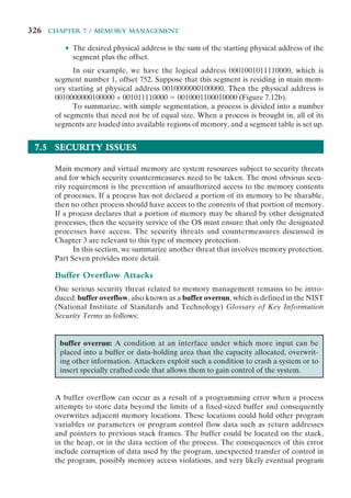
![7.5 / SECURITY ISSUES 327
termination. When done deliberately as part of an attack on a system, the transfer
of control could be to code of the attacker’s choosing, resulting in the ability to
execute arbitrary code with the privileges of the attacked process. Buffer overflow
attacks are one of the most prevalent and dangerous types of security attacks.
To illustrate the basic operation of a common type of buffer overflow,
known as stack overflow, consider the C main function given in Figure 7.13a. This
contains three variables (valid, str1, and str2),2
whose values will typically
be saved in adjacent memory locations. Their order and location depends on the
type of variable (local or global), the language and compiler used, and the target
machine architecture. For this example, we assume that they are saved in consecu-
tive memory locations, from highest to lowest, as shown in Figure 7.14.3
This is
typically the case for local variables in a C function on common processor archi-
tectures such as the Intel Pentium family. The purpose of the code fragment is to
call the function next_tag(str1) to copy into str1 some expected tag value.
2
In this example, the flag variable is saved as an integer rather than a Boolean.This is done both because
it is the classic C style and to avoid issues of word alignment in its storage. The buffers are deliberately
small to accentuate the buffer overflow issue being illustrated.
3
Address and data values are specified in hexadecimal in this and related figures. Data values are also
shown in ASCII where appropriate.
Figure 7.13 Basic Buffer Overflow Example
int main(int argc, char *argv[]) {
int valid = FALSE;
char str1[8];
char str2[8];
next_tag(str1);
gets(str2);
if (strncmp(str1, str2, 8) == 0)
valid = TRUE;
printf(“buffer1: str1(%s), str2(%s), valid(%d)n”, str1, str2, valid);
}
$ cc -g -o buffer1 buffer1.c
$ ./buffer1
START
buffer1: str1(START), str2(START), valid(1)
$ ./buffer1
EVILINPUTVALUE
buffer1: str1(TVALUE), str2(EVILINPUTVALUE), valid(0)
$ ./buffer1
BADINPUTBADINPUT
buffer1: str1(BADINPUT), str2(BADINPUTBADINPUT), valid(1)
(a) Basic buffer overflow C code
(b) Basic buffer overflow example runs](https://image.slidesharecdn.com/williamstallingsoperatingsystemsinter-230528124001-c4cbce35/85/William_Stallings_Operating_SystemsInter-pdf-349-320.jpg)
![328 CHAPTER 7 / MEMORY MANAGEMENT
Let’s assume this will be the string START. It then reads the next line from the
standard input for the program using the C library gets() function, and then
compares the string read with the expected tag. If the next line did indeed contain
just the string START, this comparison would succeed, and the variable valid would
be set to TRUE.4
This case is shown in the first of the three example program runs
in Figure 7.13b. Any other input tag would leave it with the value FALSE. Such a
code fragment might be used to parse some structured network protocol interac-
tion or formatted text file.
The problem with this code exists because the traditional C library gets()
function does not include any checking on the amount of data copied. It reads the
next line of text from the program’s standard input up until the first newline5
char-
acter occurs and copies it into the supplied buffer followed by the NULL terminator
4
In C the logical values FALSE and TRUE are simply integers with the values 0 and 1 (or indeed any
nonzero value), respectively. Symbolic defines are often used to map these symbolic names to their
underlying value, as was done in this program.
Figure 7.14 Basic Buffer Overflow Stack Values
Memory
Address
Before
gets (str2)
After
gets (str2)
Contains
Value of
. . . . . . . . . . . .
bffffbf4 34fcffbf 34fcffbf argv
4 . . . 3 . . .
bffffbf0 01000000 01000000 argc
. . . . . . . .
bffffbec c6bd0340 c6bd0340 return addr
. . . @ . . . @
bffffbe8 08fcffbf 08fcffbf old base ptr
. . . . . . . .
bffffbe4 00000000 01000000 valid
. . . . . . . .
bffffbe0 80640140 00640140
. d . @ . d . @
bffffbdc 54001540 4e505554 str1[4-7]
T . . @ N P U T
bffffbd8 53544152 42414449 str1[0-3]
S T A R B A D I
bffffbd4 00850408 4e505554 str2[4-7]
. . . . N P U T
bffffbd0 30561540 42414449 str2[0-3]
0 v . @ B A D I
. . . . . . . . . . . .
5
The newline (NL) or linefeed (LF) character is the standard end of line terminator for UNIX systems,
and hence for C, and is the character with the ASCII value 0x0a.](https://image.slidesharecdn.com/williamstallingsoperatingsystemsinter-230528124001-c4cbce35/85/William_Stallings_Operating_SystemsInter-pdf-350-320.jpg)

![330 CHAPTER 7 / MEMORY MANAGEMENT
vulnerable programs. What the attacker does with the resulting corruption of
memory varies considerably, depending on what values are being overwritten.
Defending against Buffer Overflows
Finding and exploiting a stack buffer overflow is not that difficult. The large num-
ber of exploits over the previous couple of decades clearly illustrates this. There
is consequently a need to defend systems against such attacks by either prevent-
ing them or at least detecting and aborting such attacks. Countermeasures can be
broadly classified into two categories:
• Compile-time defenses, which aim to harden programs to resist attacks in new
programs
• Run-time defenses, which aim to detect and abort attacks in existing programs
While suitable defenses have been known for a couple of decades, the very
large existing base of vulnerable software and systems hinders their deployment.
Hence the interest in run-time defenses, which can be deployed in operating
systems and updates and can provide some protection for existing vulnerable
programs.
7.6 SUMMARY
One of the most important and complex tasks of an operating system is memory
management. Memory management involves treating main memory as a resource
to be allocated to and shared among a number of active processes. To use the pro-
cessor and the I/O facilities efficiently, it is desirable to maintain as many processes
in main memory as possible. In addition, it is desirable to free programmers from
size restrictions in program development.
The basic tools of memory management are paging and segmentation. With
paging, each process is divided into relatively small, fixed-size pages. Segmentation
provides for the use of pieces of varying size. It is also possible to combine segmen-
tation and paging in a single memory management scheme.
7.7 RECOMMENDED READING
Because partitioning has been supplanted by virtual memory techniques, most OS
books offer only cursory coverage. One of the more complete and interesting treat-
ments is in [MILE92]. A thorough discussion of partitioning strategies is found in
[KNUT97].
The topics of linking and loading are covered in many books on program
development, computer architecture, and operating systems. A particularly detailed
treatment is [BECK97]. [CLAR98] also contains a good discussion. A thorough
practical discussion of this topic, with numerous OS examples, is [LEVI00].](https://image.slidesharecdn.com/williamstallingsoperatingsystemsinter-230528124001-c4cbce35/85/William_Stallings_Operating_SystemsInter-pdf-352-320.jpg)


![344 CHAPTER 8 / VIRTUAL MEMORY
Locality and Virtual Memory
The benefits of virtual memory are attractive, but is the scheme practical? At one
time, there was considerable debate on this point, but experience with numerous
operating systems has demonstrated beyond doubt that virtual memory does work.
Accordingly, virtual memory, based on either paging or paging plus segmentation,
has become an essential component of contemporary operating systems.
To understand the key issue and why virtual memory was a matter of much
debate, let us examine again the task of the OS with respect to virtual memory.
Consider a large process, consisting of a long program plus a number of arrays of
data. Over any short period of time, execution may be confined to a small section of
the program (e.g., a subroutine) and access to perhaps only one or two arrays of data.
If this is so, then it would clearly be wasteful to load in dozens of pieces for that proc-
ess when only a few pieces will be used before the program is suspended and swapped
out. We can make better use of memory by loading in just a few pieces. Then, if the
program branches to an instruction or references a data item on a piece not in main
memory, a fault is triggered. This tells the OS to bring in the desired piece.
Thus, at any one time, only a few pieces of any given process are in memory,
and therefore more processes can be maintained in memory. Furthermore, time is
saved because unused pieces are not swapped in and out of memory. However, the
OS must be clever about how it manages this scheme. In the steady state, practically
all of main memory will be occupied with process pieces, so that the processor and
OS have direct access to as many processes as possible. Thus, when the OS brings one
piece in, it must throw another out. If it throws out a piece just before it is used, then it
will just have to go get that piece again almost immediately. Too much of this leads to
a condition known as thrashing: The system spends most of its time swapping pieces
rather than executing instructions. The avoidance of thrashing was a major research
area in the 1970s and led to a variety of complex but effective algorithms. In essence,
the OS tries to guess, based on recent history, which pieces are least likely to be used
in the near future.
This reasoning is based on belief in the principle of locality, which was intro-
duced in Chapter 1 (see especially Appendix 1A). To summarize, the principle of
locality states that program and data references within a process tend to cluster.
Hence, the assumption that only a few pieces of a process will be needed over a
short period of time is valid. Also, it should be possible to make intelligent guesses
about which pieces of a process will be needed in the near future, which avoids
thrashing.
One way to confirm the principle of locality is to look at the performance of
processes in a virtual memory environment. Figure 8.1 is a rather famous diagram
that dramatically illustrates the principle of locality [HATF72]. Note that, during
the lifetime of the process, references are confined to a subset of pages.
Thus we see that the principle of locality suggests that a virtual memory
scheme may work. For virtual memory to be practical and effective, two ingre-
dients are needed. First, there must be hardware support for the paging and/or
segmentation scheme to be employed. Second, the OS must include software for
managing the movement of pages and/or segments between secondary memory
and main memory. In this section, we examine the hardware aspect and look at the](https://image.slidesharecdn.com/williamstallingsoperatingsystemsinter-230528124001-c4cbce35/85/William_Stallings_Operating_SystemsInter-pdf-366-320.jpg)
![8.1 / HARDWARE AND CONTROL STRUCTURES 345
necessary control structures, which are created and maintained by the OS but are
used by the memory management hardware. An examination of the OS issues is
provided in the next section.
Paging
The term virtual memory is usually associated with systems that employ paging,
although virtual memory based on segmentation is also used and is discussed next.
The use of paging to achieve virtual memory was first reported for the Atlas com-
puter [KILB62] and soon came into widespread commercial use.
In the discussion of simple paging, we indicated that each process has its
own page table, and when all of its pages are loaded into main memory, the page
Execution time
18
Page
numbers
20
22
24
26
28
30
32
34
Figure 8.1 Paging Behavior](https://image.slidesharecdn.com/williamstallingsoperatingsystemsinter-230528124001-c4cbce35/85/William_Stallings_Operating_SystemsInter-pdf-367-320.jpg)


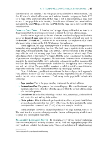

![8.1 / HARDWARE AND CONTROL STRUCTURES 351
recently used pages. Therefore, most references will involve page table entries in
the cache. Studies of the VAX TLB have shown that this scheme can significantly
improve performance [CLAR85, SATY81].
There are a number of additional details concerning the actual organization
of the TLB. Because the TLB contains only some of the entries in a full page table,
we cannot simply index into the TLB based on page number. Instead, each entry
in the TLB must include the page number as well as the complete page table entry.
The processor is equipped with hardware that allows it to interrogate simultane-
ously a number of TLB entries to determine if there is a match on page number.
This technique is referred to as associative mapping and is contrasted with the direct
mapping, or indexing, used for lookup in the page table in Figure 8.9. The design of
the TLB also must consider the way in which entries are organized in the TLB and
which entry to replace when a new entry is brought in. These issues must be consid-
ered in any hardware cache design. This topic is not pursued here; the reader may
consult a treatment of cache design for further details (e.g., [STAL10]).
Finally, the virtual memory mechanism must interact with the cache system
(not the TLB cache, but the main memory cache). This is illustrated in Figure 8.10.
A virtual address will generally be in the form of a page number, offset. First, the
memory system consults the TLB to see if the matching page table entry is present.
If it is, the real (physical) address is generated by combining the frame number with
the offset. If not, the entry is accessed from a page table. Once the real address is
Page # Offset
Frame #
Virtual address
Offset
Offset
Load
page
Page table
Main memory
Secondary
memory
Real address
Translation
lookaside buffer
TLB hit
TLB miss
Page fault
Figure 8.7 Use of a Translation Lookaside Buffer](https://image.slidesharecdn.com/williamstallingsoperatingsystemsinter-230528124001-c4cbce35/85/William_Stallings_Operating_SystemsInter-pdf-373-320.jpg)
![352 CHAPTER 8 / VIRTUAL MEMORY
generated, which is in the form of a tag2
and a remainder, the cache is consulted to
see if the block containing that word is present. If so, it is returned to the CPU. If
not, the word is retrieved from main memory.
The reader should be able to appreciate the complexity of the CPU hardware
involved in a single memory reference. The virtual address is translated into a real
address. This involves reference to a page table entry, which may be in the TLB, in
main memory, or on disk. The referenced word may be in cache, main memory, or
on disk. If the referenced word is only on disk, the page containing the word must
2
See Figure 1.17. Typically, a tag is just the leftmost bits of the real address. Again, for a more detailed
discussion of caches, see [STAL10].
Start
CPU checks the TLB
Page table
entry in
TLB?
Access page table
Update TLB
Yes
Yes
No
No
No
Yes
CPU generates
physical address
OS instructs CPU
to read the page
from disk
CPU activates
I/O hardware
Page fault
handling routine
Return to
faulted instruction
Page tables
updated
Perform page
replacement
Page transferred
from disk to
main memory
Page
in main
memory?
Memory
full?
Figure 8.8 Operation of Paging and Translation Lookaside Buffer (TLB)](https://image.slidesharecdn.com/williamstallingsoperatingsystemsinter-230528124001-c4cbce35/85/William_Stallings_Operating_SystemsInter-pdf-374-320.jpg)


![8.1 / HARDWARE AND CONTROL STRUCTURES 355
size, the fault rate drops as the number of pages maintained in main memory grows.3
Thus, a software policy (the amount of memory to allocate to each process) inter-
acts with a hardware design decision (page size).
Table 8.3 lists the page sizes used on some machines.
Finally, the design issue of page size is related to the size of physical main memory
and program size. At the same time that main memory is getting larger, the address
space used by applications is also growing. The trend is most obvious on personal
computers and workstations, where applications are becoming increasingly complex.
Furthermore, contemporary programming techniques used in large programs tend to
decrease the locality of references within a process [HUCK93]. For example,
• Object-oriented techniques encourage the use of many small program and
data modules with references scattered over a relatively large number of ob-
jects over a relatively short period of time.
• Multithreaded applications may result in abrupt changes in the instruction
stream and in scattered memory references.
For a given size of TLB, as the memory size of processes grows and as locality
decreases, the hit ratio on TLB accesses declines. Under these circumstances, the
TLB can become a performance bottleneck (e.g., see [CHEN92]).
One way to improve TLB performance is to use a larger TLB with more
entries. However, TLB size interacts with other aspects of the hardware design,
such as the main memory cache and the number of memory accesses per instruction
cycle [TALL92]. The upshot is that TLB size is unlikely to grow as rapidly as main
memory size. An alternative is to use larger page sizes so that each page table entry
in the TLB refers to a larger block of memory. But we have just seen that the use of
large page sizes can lead to performance degradation.
Table 8.3 Example Page Sizes
Computer Page Size
Atlas 512 48-bit words
Honeywell-Multics 1,024 36-bit words
IBM 370/XA and 370/ESA 4 Kbytes
VAX family 512 bytes
IBM AS/400 512 bytes
DEC Alpha 8 Kbytes
MIPS 4 Kbytes to 16 Mbytes
UltraSPARC 8 Kbytes to 4 Mbytes
Pentium 4 Kbytes or 4 Mbytes
Intel Itanium 4 Kbytes to 256 Mbytes
Intel core i7 4 Kbytes to 1 Gbyte
3
The parameter W represents working set size, a concept discussed in Section 8.2.](https://image.slidesharecdn.com/williamstallingsoperatingsystemsinter-230528124001-c4cbce35/85/William_Stallings_Operating_SystemsInter-pdf-377-320.jpg)
![356 CHAPTER 8 / VIRTUAL MEMORY
Accordingly, a number of designers have investigated the use of multiple
page sizes [TALL92, KHAL93], and several microprocessor architectures support
multiple pages sizes, including MIPS R4000, Alpha, UltraSPARC, Pentium, and
IA-64. Multiple page sizes provide the flexibility needed to use a TLB effectively.
For example, large contiguous regions in the address space of a process, such as pro-
gram instructions, may be mapped using a small number of large pages rather than
a large number of small pages, while thread stacks may be mapped using the small
page size. However, most commercial operating systems still support only one page
size, regardless of the capability of the underlying hardware. The reason for this is
that page size affects many aspects of the OS; thus, a change to multiple page sizes
is a complex undertaking (see [GANA98] for a discussion).
Segmentation
VIRTUAL MEMORY IMPLICATIONS Segmentation allows the programmer to view
memory as consisting of multiple address spaces or segments. Segments may be of
unequal, indeed dynamic, size. Memory references consist of a (segment number,
offset) form of address.
This organization has a number of advantages to the programmer over a non-
segmented address space:
1. It simplifies the handling of growing data structures. If the programmer does
not know ahead of time how large a particular data structure will become, it is
necessary to guess unless dynamic segment sizes are allowed. With segmented
virtual memory, the data structure can be assigned its own segment, and the
OS will expand or shrink the segment as needed. If a segment that needs to be
expanded is in main memory and there is insufficient room, the OS may move
the segment to a larger area of main memory, if available, or swap it out. In
the latter case, the enlarged segment would be swapped back in at the next
opportunity.
2. It allows programs to be altered and recompiled independently, without
requiring the entire set of programs to be relinked and reloaded. Again, this is
accomplished using multiple segments.
3. It lends itself to sharing among processes. A programmer can place a utility
program or a useful table of data in a segment that can be referenced by other
processes.
4. It lends itself to protection. Because a segment can be constructed to contain a
well-defined set of programs or data, the programmer or system administrator
can assign access privileges in a convenient fashion.
ORGANIZATION In the discussion of simple segmentation, we indicated that each
process has its own segment table, and when all of its segments are loaded into main
memory, the segment table for a process is created and loaded into main memory.
Each segment table entry contains the starting address of the corresponding segment
in main memory, as well as the length of the segment. The same device, a segment
table, is needed when we consider a virtual memory scheme based on segmentation.
Again, it is typical to associate a unique segment table with each process. In this](https://image.slidesharecdn.com/williamstallingsoperatingsystemsinter-230528124001-c4cbce35/85/William_Stallings_Operating_SystemsInter-pdf-378-320.jpg)


![362 CHAPTER 8 / VIRTUAL MEMORY
The prepaging policy could be employed either when a process first starts up,
in which case the programmer would somehow have to designate desired pages, or
every time a page fault occurs. This latter course would seem preferable because
it is invisible to the programmer. However, the utility of prepaging has not been
established [MAEK87].
Prepaging should not be confused with swapping. When a process is swapped
out of memory and put in a suspended state, all of its resident pages are moved out.
When the process is resumed, all of the pages that were previously in main memory
are returned to main memory.
Placement Policy
The placement policy determines where in real memory a process piece is to reside.
In a pure segmentation system, the placement policy is an important design issue;
policies such as best-fit, first-fit, and so on, which were discussed in Chapter 7, are
possible alternatives. However, for a system that uses either pure paging or paging
combined with segmentation, placement is usually irrelevant because the address
translation hardware and the main memory access hardware can perform their
functions for any page-frame combination with equal efficiency.
There is one area in which placement does become a concern, and this is a
subject of research and development. On a so-called nonuniform memory access
(NUMA) multiprocessor, the distributed, shared memory of the machine can be
referenced by any processor on the machine, but the time for accessing a particular
physical location varies with the distance between the processor and the memory
module. Thus, performance depends heavily on the extent to which data reside
close to the processors that use them [LARO92, BOLO89, COX89]. For NUMA
systems, an automatic placement strategy is desirable to assign pages to the memory
module that provides the best performance.
Replacement Policy
In most operating system texts, the treatment of memory management includes a
section entitled “replacement policy,” which deals with the selection of a page in
main memory to be replaced when a new page must be brought in. This topic is
sometimes difficult to explain because several interrelated concepts are involved:
• How many page frames are to be allocated to each active process
• Whether the set of pages to be considered for replacement should be limited
to those of the process that caused the page fault or encompass all the page
frames in main memory
• Among the set of pages considered, which particular page should be selected
for replacement
We shall refer to the first two concepts as resident set management, which is dealt
with in the next subsection, and reserve the term replacement policy for the third
concept, which is discussed in this subsection.
The area of replacement policy is probably the most studied of any area of
memory management. When all of the frames in main memory are occupied and
it is necessary to bring in a new page to satisfy a page fault, the replacement policy](https://image.slidesharecdn.com/williamstallingsoperatingsystemsinter-230528124001-c4cbce35/85/William_Stallings_Operating_SystemsInter-pdf-384-320.jpg)
![8.2 / OPERATING SYSTEM SOFTWARE 363
determines which page currently in memory is to be replaced. All of the policies
have as their objective that the page that is removed should be the page least likely
to be referenced in the near future. Because of the principle of locality, there is
often a high correlation between recent referencing history and near-future refer-
encing patterns. Thus, most policies try to predict future behavior on the basis of
past behavior. One trade-off that must be considered is that the more elaborate and
sophisticated the replacement policy, the greater will be the hardware and software
overhead to implement it.
FRAME LOCKING One restriction on replacement policy needs to be mentioned
before looking at various algorithms: Some of the frames in main memory may be
locked. When a frame is locked, the page currently stored in that frame may not be
replaced. Much of the kernel of the OS, as well as key control structures, are held in
locked frames. In addition, I/O buffers and other time-critical areas may be locked
into main memory frames. Locking is achieved by associating a lock bit with each
frame. This bit may be kept in a frame table as well as being included in the current
page table.
BASIC ALGORITHMS Regardless of the resident set management strategy (discussed
in the next subsection), there are certain basic algorithms that are used for the
selection of a page to replace. Replacement algorithms that have been discussed in
the literature include
• Optimal
• Least recently used (LRU)
• First-in-first-out (FIFO)
• Clock
The optimal policy selects for replacement that page for which the time to the
next reference is the longest. It can be shown that this policy results in the fewest
number of page faults [BELA66]. Clearly, this policy is impossible to implement,
because it would require the OS to have perfect knowledge of future events. However,
it does serve as a standard against which to judge real-world algorithms.
Figure 8.15 gives an example of the optimal policy. The example assumes a
fixed frame allocation (fixed resident set size) for this process of three frames. The
execution of the process requires reference to five distinct pages. The page address
stream formed by executing the program is
2 3 2 1 5 2 4 5 3 2 5 2
which means that the first page referenced is 2, the second page referenced is 3, and
so on. The optimal policy produces three page faults after the frame allocation has
been filled.
The least recently used (LRU) policy replaces the page in memory that has
not been referenced for the longest time. By the principle of locality, this should
be the page least likely to be referenced in the near future. And, in fact, the LRU
policy does nearly as well as the optimal policy. The problem with this approach is
the difficulty in implementation. One approach would be to tag each page with the](https://image.slidesharecdn.com/williamstallingsoperatingsystemsinter-230528124001-c4cbce35/85/William_Stallings_Operating_SystemsInter-pdf-385-320.jpg)

![8.2 / OPERATING SYSTEM SOFTWARE 365
policy is very simple to implement but performs relatively poorly. Over the years,
OS designers have tried a number of other algorithms to approximate the perform-
ance of LRU while imposing little overhead. Many of these algorithms are variants
of a scheme referred to as the clock policy.
The simplest form of clock policy requires the association of an additional
bit with each frame, referred to as the use bit. When a page is first loaded into
a frame in memory, the use bit for that frame is set to 1. Whenever the page is
subsequently referenced (after the reference that generated the page fault), its
use bit is set to 1. For the page replacement algorithm, the set of frames that are
candidates for replacement (this process: local scope; all of main memory: global
scope5
) is considered to be a circular buffer, with which a pointer is associated.
When a page is replaced, the pointer is set to indicate the next frame in the buffer
after the one just updated. When it comes time to replace a page, the OS scans
the buffer to find a frame with a use bit set to 0. Each time it encounters a frame
with a use bit of 1, it resets that bit to 0 and continues on. If any of the frames in
the buffer have a use bit of 0 at the beginning of this process, the first such frame
encountered is chosen for replacement. If all of the frames have a use bit of 1,
then the pointer will make one complete cycle through the buffer, setting all the
use bits to 0, and stop at its original position, replacing the page in that frame.
We can see that this policy is similar to FIFO, except that, in the clock policy, any
frame with a use bit of 1 is passed over by the algorithm. The policy is referred
to as a clock policy because we can visualize the page frames as laid out in a circle.
A number of operating systems have employed some variation of this simple clock
policy (e.g., Multics [CORB68]).
Figure 8.16 provides an example of the simple clock policy mechanism. A cir-
cular buffer of n main memory frames is available for page replacement. Just prior
to the replacement of a page from the buffer with incoming page 727, the next frame
pointer points at frame 2, which contains page 45. The clock policy is now executed.
Because the use bit for page 45 in frame 2 is equal to 1, this page is not replaced.
Instead, the use bit is set to 0 and the pointer advances. Similarly, page 191 in frame
3 is not replaced; its use bit is set to 0 and the pointer advances. In the next frame,
frame 4, the use bit is set to 0. Therefore, page 556 is replaced with page 727. The
use bit is set to 1 for this frame and the pointer advances to frame 5, completing the
page replacement procedure.
The behavior of the clock policy is illustrated in Figure 8.15. The presence
of an asterisk indicates that the corresponding use bit is equal to 1, and the arrow
indicates the current position of the pointer. Note that the clock policy is adept at
protecting frames 2 and 5 from replacement.
Figure 8.17 shows the results of an experiment reported in [BAER80], which
compares the four algorithms that we have been discussing; it is assumed that the
number of page frames assigned to a process is fixed. The results are based on the
execution of 0.25 × 10⁶
references in a FORTRAN program, using a page size of 256
words. Baer ran the experiment with frame allocations of 6, 8, 10, 12, and 14 frames.
The differences among the four policies are most striking at small allocations, with
5
The concept of scope is discussed in the subsection “Replacement Scope,” subsequently.](https://image.slidesharecdn.com/williamstallingsoperatingsystemsinter-230528124001-c4cbce35/85/William_Stallings_Operating_SystemsInter-pdf-387-320.jpg)
![366 CHAPTER 8 / VIRTUAL MEMORY
FIFO being over a factor of 2 worse than optimal. All four curves have the same shape
as the idealized behavior shown in Figure 8.11b. In order to run efficiently, we would
like to be to the right of the knee of the curve (with a small page fault rate) while
keeping a small frame allocation (to the left of the knee of the curve). These two con-
straints indicate that a desirable mode of operation would be at the knee of the curve.
Almost identical results have been reported in [FINK88], again showing a max-
imum spread of about a factor of 2. Finkel’s approach was to simulate the effects of
various policies on a synthesized page-reference string of 10,000 references selected
0
6
1
2
3
4
5
7
8
n ⫺ 1
n ⫺ 1
Page 19
Use ⫽ 1
Page 1
Use ⫽ 1
Next frame
pointer
Page 45
Use ⫽ 1
Page 191
Use ⫽ 1
Page 556
Use ⫽ 0
Page 13
Use ⫽ 0
Page 67
Use ⫽ 1
Page 33
Use ⫽ 1
Page 222
Use ⫽ 0
Page 9
Use ⫽ 1
(a) State of buffer just prior to a page replacement
0
6
1
2
3
4
5
7
8
Page 19
Use ⫽ 1
Page 1
Use ⫽ 1
Page 45
Use ⫽ 0
Page 191
Use ⫽ 0
Page 727
Use ⫽ 1
Page 13
Use ⫽ 0
Page 67
Use ⫽ 1
Page 33
Use ⫽ 1
Page 222
Use ⫽ 0
Page 9
Use ⫽ 1
(b) State of buffer just after the next page replacement
First frame in
circular buffer of
frames that are
candidates for replacement
Figure 8.16 Example of Clock Policy Operation](https://image.slidesharecdn.com/williamstallingsoperatingsystemsinter-230528124001-c4cbce35/85/William_Stallings_Operating_SystemsInter-pdf-388-320.jpg)
![8.2 / OPERATING SYSTEM SOFTWARE 367
from a virtual space of 100 pages. To approximate the effects of the principle of
locality, an exponential distribution for the probability of referencing a particular
page was imposed. Finkel observes that some might be led to conclude that there
is little point in elaborate page replacement algorithms when only a factor of 2 is at
stake. But he notes that this difference will have a noticeable effect either on main
memory requirements (to avoid degrading operating system performance) or oper-
ating system performance (to avoid enlarging main memory).
The clock algorithm has also been compared to these other algorithms when
a variable allocation and either global or local replacement scope (see the follow-
ing discussion of replacement policy) is used [CARR81, CARR84]. The clock algo-
rithm was found to approximate closely the performance of LRU.
The clock algorithm can be made more powerful by increasing the number
of bits that it employs.6
In all processors that support paging, a modify bit is associ-
ated with every page in main memory and hence with every frame of main memory.
This bit is needed so that, when a page has been modified, it is not replaced until it
has been written back into secondary memory. We can exploit this bit in the clock
algorithm in the following way. If we take the use and modify bits into account, each
frame falls into one of four categories:
• Not accessed recently, not modified (u ⫽ 0; m ⫽ 0)
• Accessed recently, not modified (u ⫽ 1; m ⫽ 0)
• Not accessed recently, modified (u ⫽ 0; m ⫽ 1)
• Accessed recently, modified (u ⫽ 1; m ⫽ 1)
With this classification, the clock algorithm performs as follows:
1. Beginning at the current position of the pointer, scan the frame buffer. During
this scan, make no changes to the use bit. The first frame encountered with
(u ⫽ 0; m ⫽ 0) is selected for replacement.
0
6 8
Number of frames allocated
Page
faults
per
1000
references
10 12 14
5
10
15
20
25
30
35
FIFO
CLOCK
LRU
OPT
40
Figure 8.17 Comparison of Fixed-Allocation, Local Page
Replacement Algorithms
6
On the other hand, if we reduce the number of bits employed to zero, the clock algorithm degenerates
to FIFO.](https://image.slidesharecdn.com/williamstallingsoperatingsystemsinter-230528124001-c4cbce35/85/William_Stallings_Operating_SystemsInter-pdf-389-320.jpg)
![368 CHAPTER 8 / VIRTUAL MEMORY
2. If step 1 fails, scan again, looking for the frame with (u ⫽ 0; m ⫽ 1). The first
such frame encountered is selected for replacement. During this scan, set the
use bit to 0 on each frame that is bypassed.
3. If step 2 fails, the pointer should have returned to its original position and all
of the frames in the set will have a use bit of 0. Repeat step 1 and, if necessary,
step 2. This time, a frame will be found for the replacement.
In summary, the page replacement algorithm cycles through all of the pages
in the buffer looking for one that has not been modified since being brought in and
has not been accessed recently. Such a page is a good bet for replacement and has
the advantage that, because it is unmodified, it does not need to be written back
out to secondary memory. If no candidate page is found in the first sweep, the algo-
rithm cycles through the buffer again, looking for a modified page that has not been
accessed recently. Even though such a page must be written out to be replaced,
because of the principle of locality, it may not be needed again anytime soon. If
this second pass fails, all of the frames in the buffer are marked as having not been
accessed recently and a third sweep is performed.
This strategy was used on an earlier version of the Macintosh virtual memory
scheme [GOLD89], illustrated in Figure 8.18. The advantage of this algorithm over
Page 9
not accessed
recently;
modified
First frame in
circular buffer
for this process
Last
replaced
Next
replaced
Page 7
not accessed
recently;
modified
Page 97
not accessed
recently;
modified
Page 46
not accessed
recently;
modified
Page 94
not accessed
recently;
not modified
Page 47
not accessed
recently;
not modified
Page 13
not accessed
recently;
not modified
Page 95
accessed
recently;
not modified
Page 45
accessed
recently;
not modified
Page 121
accessed
recently;
not modified
Page 96
accessed
recently;
not modified
0
1
2
3
4
5
6
7
8
9
n ⫺ 1
Figure 8.18 The Clock Page Replacement Algorithm [GOLD89]](https://image.slidesharecdn.com/williamstallingsoperatingsystemsinter-230528124001-c4cbce35/85/William_Stallings_Operating_SystemsInter-pdf-390-320.jpg)
![8.2 / OPERATING SYSTEM SOFTWARE 369
the simple clock algorithm is that pages that are unchanged are given preference
for replacement. Because a page that has been modified must be written out before
being replaced, there is an immediate saving of time.
PAGE BUFFERING Although LRU and the clock policies are superior to FIFO,
they both involve complexity and overhead not suffered with FIFO. In addition,
there is the related issue that the cost of replacing a page that has been modified is
greater than for one that has not, because the former must be written back out to
secondary memory.
An interesting strategy that can improve paging performance and allow
the use of a simpler page replacement policy is page buffering. The VAX VMS
approach is representative. The page replacement algorithm is simple FIFO. To
improve performance, a replaced page is not lost but rather is assigned to one of
two lists: the free page list if the page has not been modified, or the modified page
list if it has. Note that the page is not physically moved about in main memory;
instead, the entry in the page table for this page is removed and placed in either the
free or modified page list.
The free page list is a list of page frames available for reading in pages. VMS
tries to keep some small number of frames free at all times. When a page is to be
read in, the page frame at the head of the list is used, destroying the page that was
there. When an unmodified page is to be replaced, it remains in memory and its
page frame is added to the tail of the free page list. Similarly, when a modified page
is to be written out and replaced, its page frame is added to the tail of the modified
page list.
The important aspect of these maneuvers is that the page to be replaced
remains in memory. Thus if the process references that page, it is returned to the
resident set of that process at little cost. In effect, the free and modified page lists act
as a cache of pages. The modified page list serves another useful function: Modified
pages are written out in clusters rather than one at a time. This significantly reduces
the number of I/O operations and therefore the amount of disk access time.
A simpler version of page buffering is implemented in the Mach operat-
ing system [RASH88]. In this case, no distinction is made between modified and
unmodified pages.
REPLACEMENT POLICY AND CACHE SIZE As discussed earlier, main memory size
is getting larger and the locality of applications is decreasing. In compensation,
cache sizes have been increasing. Large cache sizes, even multimegabyte ones, are
now feasible design alternatives [BORG90]. With a large cache, the replacement of
virtual memory pages can have a performance impact. If the page frame selected
for replacement is in the cache, then that cache block is lost as well as the page that
it holds.
In systems that use some form of page buffering, it is possible to improve
cache performance by supplementing the page replacement policy with a policy for
page placement in the page buffer. Most operating systems place pages by selecting
an arbitrary page frame from the page buffer; typically a first-in-first-out discipline
is used. A study reported in [KESS92] shows that a careful page placement strategy
can result in 10–20% fewer cache misses than naive placement.](https://image.slidesharecdn.com/williamstallingsoperatingsystemsinter-230528124001-c4cbce35/85/William_Stallings_Operating_SystemsInter-pdf-391-320.jpg)
![370 CHAPTER 8 / VIRTUAL MEMORY
Several page placement algorithms are examined in [KESS92]. The details
are beyond the scope of this book, as they depend on the details of cache structure
and policies. The essence of these strategies is to bring consecutive pages into main
memory in such a way as to minimize the number of page frames that are mapped
into the same cache slots.
Resident Set Management
RESIDENT SET SIZE With paged virtual memory, it is not necessary and indeed
may not be possible to bring all of the pages of a process into main memory to
prepare it for execution. Thus, the OS must decide how many pages to bring in, that
is, how much main memory to allocate to a particular process. Several factors come
into play:
• The smaller the amount of memory allocated to a process, the more processes
that can reside in main memory at any one time. This increases the probability
that the OS will find at least one ready process at any given time and hence
reduces the time lost due to swapping.
• If a relatively small number of pages of a process are in main memory, then,
despite the principle of locality, the rate of page faults will be rather high (see
Figure 8.11b).
• Beyond a certain size, additional allocation of main memory to a particular
process will have no noticeable effect on the page fault rate for that process
because of the principle of locality.
With these factors in mind, two sorts of policies are to be found in contempo-
rary operating systems. A fixed-allocation policy gives a process a fixed number of
frames in main memory within which to execute. That number is decided at initial
load time (process creation time) and may be determined based on the type of proc-
ess (interactive, batch, type of application) or may be based on guidance from the
programmer or system manager. With a fixed-allocation policy, whenever a page
fault occurs in the execution of a process, one of the pages of that process must be
replaced by the needed page.
A variable-allocation policy allows the number of page frames allocated to a
process to be varied over the lifetime of the process. Ideally, a process that is suf-
fering persistently high levels of page faults, indicating that the principle of local-
ity only holds in a weak form for that process, will be given additional page frames
to reduce the page fault rate; whereas a process with an exceptionally low page
fault rate, indicating that the process is quite well behaved from a locality point of
view, will be given a reduced allocation, with the hope that this will not noticeably
increase the page fault rate. The use of a variable-allocation policy relates to the
concept of replacement scope, as explained in the next subsection.
The variable-allocation policy would appear to be the more powerful one.
However, the difficulty with this approach is that it requires the OS to assess
the behavior of active processes. This inevitably requires software overhead in
the OS and is dependent on hardware mechanisms provided by the processor
platform.](https://image.slidesharecdn.com/williamstallingsoperatingsystemsinter-230528124001-c4cbce35/85/William_Stallings_Operating_SystemsInter-pdf-392-320.jpg)
![8.2 / OPERATING SYSTEM SOFTWARE 371
REPLACEMENT SCOPE The scope of a replacement strategy can be categorized as
global or local. Both types of policies are activated by a page fault when there are no
free page frames. A local replacement policy chooses only among the resident pages
of the process that generated the page fault in selecting a page to replace. A global
replacement policy considers all unlocked pages in main memory as candidates for
replacement, regardless of which process owns a particular page. While it happens
that local policies are easier to analyze, there is no convincing evidence that they
perform better than global policies, which are attractive because of their simplicity
of implementation and minimal overhead [CARR84, MAEK87].
There is a correlation between replacement scope and resident set size
(Table 8.5). A fixed resident set implies a local replacement policy: To hold the size
of a resident set fixed, a page that is removed from main memory must be replaced
by another page from the same process. A variable-allocation policy can clearly
employ a global replacement policy: The replacement of a page from one process in
main memory with that of another causes the allocation of one process to grow by
one page and that of the other to shrink by one page. We shall also see that variable
allocation and local replacement is a valid combination. We now examine these
three combinations.
FIXED ALLOCATION, LOCAL SCOPE For this case, we have a process that is running
in main memory with a fixed number of frames. When a page fault occurs, the OS
must choose which page from among the currently resident pages for this process
is to be replaced. Replacement algorithms such as those discussed in the preceding
subsection can be used.
With a fixed-allocation policy, it is necessary to decide ahead of time the amount
of allocation to give to a process. This could be decided on the basis of the type
of application and the amount requested by the program. The drawback to this
approach is twofold: If allocations tend to be too small, then there will be a high page
fault rate, causing the entire multiprogramming system to run slowly. If allocations
tend to be unnecessarily large, then there will be too few programs in main memory
and there will be either considerable processor idle time or considerable time spent
in swapping.
Table 8.5 Resident Set Management
Local Replacement Global Replacement
Fixed Allocation • Number of frames allocated to a
process is fixed.
• Page to be replaced is chosen from
among the frames allocated to that
process.
• Not possible.
Variable Allocation • The number of frames allocated to a
process may be changed from time to
time to maintain the working set of the
process.
• Page to be replaced is chosen from
among the frames allocated to that
process.
• Page to be replaced is chosen from all
available frames in main memory; this
causes the size of the resident set of
processes to vary.](https://image.slidesharecdn.com/williamstallingsoperatingsystemsinter-230528124001-c4cbce35/85/William_Stallings_Operating_SystemsInter-pdf-393-320.jpg)
![372 CHAPTER 8 / VIRTUAL MEMORY
VARIABLE ALLOCATION, GLOBAL SCOPE This combination is perhaps the easiest
to implement and has been adopted in a number of operating systems. At any given
time, there are a number of processes in main memory, each with a certain number
of frames allocated to it. Typically, the OS also maintains a list of free frames. When
a page fault occurs, a free frame is added to the resident set of a process and the
page is brought in. Thus, a process experiencing page faults will gradually grow in
size, which should help reduce overall page faults in the system.
The difficulty with this approach is in the replacement choice. When there
are no free frames available, the OS must choose a page currently in memory to
replace. The selection is made from among all of the frames in memory, except
for locked frames such as those of the kernel. Using any of the policies discussed
in the preceding subsection, the page selected for replacement can belong to any
of the resident processes; there is no discipline to determine which process should
lose a page from its resident set. Therefore, the process that suffers the reduction in
resident set size may not be optimum.
One way to counter the potential performance problems of a variable-allocation,
global-scope policy is to use page buffering. In this way, the choice of which page to
replace becomes less significant, because the page may be reclaimed if it is referenced
before the next time that a block of pages are overwritten.
VARIABLE ALLOCATION, LOCAL SCOPE The variable-allocation, local-scope
strategy attempts to overcome the problems with a global-scope strategy. It can be
summarized as follows:
1. When a new process is loaded into main memory, allocate to it a certain
number of page frames as its resident set, based on application type, program
request, or other criteria. Use either prepaging or demand paging to fill up the
allocation.
2. When a page fault occurs, select the page to replace from among the resident
set of the process that suffers the fault.
3. From time to time, reevaluate the allocation provided to the process, and
increase or decrease it to improve overall performance.
With this strategy, the decision to increase or decrease a resident set size is a
deliberate one and is based on an assessment of the likely future demands of active
processes. Because of this evaluation, such a strategy is more complex than a simple
global replacement policy. However, it may yield better performance.
The key elements of the variable-allocation, local-scope strategy are the cri-
teria used to determine resident set size and the timing of changes. One specific
strategy that has received much attention in the literature is known as the working
set strategy. Although a true working set strategy would be difficult to implement, it
is useful to examine it as a baseline for comparison.
The working set is a concept introduced and popularized by Denning
[DENN68, DENN70, DENN80b]; it has had a profound impact on virtual memory
management design. The working set with parameter ⌬ for a process at virtual
time t, which we designate as W(t, ⌬), is the set of pages of that process that have
been referenced in the last ⌬ virtual time units.](https://image.slidesharecdn.com/williamstallingsoperatingsystemsinter-230528124001-c4cbce35/85/William_Stallings_Operating_SystemsInter-pdf-394-320.jpg)
![8.2 / OPERATING SYSTEM SOFTWARE 373
Virtual time is defined as follows. Consider a sequence of memory references,
r(1), r(2), ...., in which r(i) is the page that contains the ith virtual address gener-
ated by a given process. Time is measured in memory references; thus t ⫽ 1, 2, 3, ....
measures the process’s internal virtual time.
Let us consider each of the two variables of W. The variable ⌬ is a window
of virtual time over which the process is observed. The working set size will be a
nondecreasing function of the window size. The result is illustrated in Figure 8.19
(based on [BACH86]), which shows a sequence of page references for a process.
The dots indicate time units in which the working set does not change. Note that the
larger the window size, the larger is the working set. This can be expressed in the
following relationship:
W(t,⌬ + 1) 傶 W(t,⌬)
The working set is also a function of time. If a process executes over ⌬ time
units and uses only a single page, then |W(t,⌬)| = 1. A working set can also grow
as large as the number of pages N of the process if many different pages are rapidly
addressed and if the window size allows. Thus,
1 … |W(t,⌬)| … min(⌬,N)
Figure 8.20 indicates the way in which the working set size can vary over time
for a fixed value of Δ. For many programs, periods of relatively stable working set
Figure 8.19 Working Set of Process as Defined by Window Size
Sequence of
Page
References Window Size, ⌬
W 2 3 4 5
24 24 24 24 24
15 24 15 24 15 24 15 24 15
18 15 18 24 15 18 24 15 18 24 15 18
23 18 23 15 18 23 24 15 18 23 24 15 18 23
24 23 24 18 23 24 • •
17 24 17 23 24 17 18 23 24 17 15 18 23 24 17
18 17 18 24 17 18 • 18 23 24 17
24 18 24 • 24 17 18 •
18 • 18 24 • 24 17 18
17 18 17 24 18 17 • •
17 17 18 17 • •
15 17 15 17 15 18 17 15 24 18 17 15
24 15 24 17 15 24 17 15 24 •
17 24 17 • • 17 15 24
24 • 24 17 • •
18 24 18 17 24 18 17 24 18 15 17 24 18](https://image.slidesharecdn.com/williamstallingsoperatingsystemsinter-230528124001-c4cbce35/85/William_Stallings_Operating_SystemsInter-pdf-395-320.jpg)
![374 CHAPTER 8 / VIRTUAL MEMORY
sizes alternate with periods of rapid change. When a process first begins execut-
ing, it gradually builds up to a working set as it references new pages. Eventually,
by the principle of locality, the process should stabilize on a certain set of pages.
Subsequent transient periods reflect a shift of the program to a new locality. During
the transition phase, some of the pages from the old locality remain within the win-
dow, ⌬, causing a surge in the size of the working set as new pages are referenced.
As the window slides past these page references, the working set size declines until
it contains only those pages from the new locality.
This concept of a working set can be used to guide a strategy for resident
set size:
1. Monitor the working set of each process.
2. Periodically remove from the resident set of a process those pages that are not
in its working set. This is essentially an LRU policy.
3. A process may execute only if its working set is in main memory (i.e., if its
resident set includes its working set).
This strategy is appealing because it takes an accepted principle, the principle
of locality, and exploits it to achieve a memory management strategy that should
minimize page faults. Unfortunately, there are a number of problems with the work-
ing set strategy:
1. The past does not always predict the future. Both the size and the membership
of the working set will change over time (e.g., see Figure 8.20).
2. A true measurement of working set for each process is impractical. It would
be necessary to time-stamp every page reference for every process using the
Transient Transient Transient Transient
Stable
⌬
Stable Stable Stable
Working
set
size
Time
Figure 8.20 Typical Graph of Working Set Size [MAEK87]](https://image.slidesharecdn.com/williamstallingsoperatingsystemsinter-230528124001-c4cbce35/85/William_Stallings_Operating_SystemsInter-pdf-396-320.jpg)
![8.2 / OPERATING SYSTEM SOFTWARE 375
virtual time of that process and then maintain a time-ordered queue of pages
for each process.
3. The optimal value of ⌬ is unknown and in any case would vary.
Nevertheless, the spirit of this strategy is valid, and a number of operating
systems attempt to approximate a working set strategy. One way to do this is to
focus not on the exact page references but on the page fault rate of a process. As
Figure 8.11b illustrates, the page fault rate falls as we increase the resident set size of
a process. The working set size should fall at a point on this curve such as indicated
by W in the figure. Therefore, rather than monitor the working set size directly, we
can achieve comparable results by monitoring the page fault rate. The line of reason-
ing is as follows: If the page fault rate for a process is below some minimum thresh-
old, the system as a whole can benefit by assigning a smaller resident set size to this
process (because more page frames are available for other processes) without harm-
ing the process (by causing it to incur increased page faults). If the page fault rate
for a process is above some maximum threshold, the process can benefit from an
increased resident set size (by incurring fewer faults) without degrading the system.
An algorithm that follows this strategy is the page fault frequency (PFF) algo-
rithm [CHU72, GUPT78]. It requires a use bit to be associated with each page in
memory. The bit is set to 1 when that page is accessed. When a page fault occurs,
the OS notes the virtual time since the last page fault for that process; this could
be done by maintaining a counter of page references. A threshold F is defined. If
the amount of time since the last page fault is less than F, then a page is added to the
resident set of the process. Otherwise, discard all pages with a use bit of 0, and
shrink the resident set accordingly. At the same time, reset the use bit on the remain-
ing pages of the process to 0. The strategy can be refined by using two thresholds: an
upper threshold that is used to trigger a growth in the resident set size, and a lower
threshold that is used to trigger a contraction in the resident set size.
The time between page faults is the reciprocal of the page fault rate. Although
it would seem to be better to maintain a running average of the page fault rate, the
use of a single time measurement is a reasonable compromise that allows decisions
about resident set size to be based on the page fault rate. If such a strategy is sup-
plemented with page buffering, the resulting performance should be quite good.
Nevertheless, there is a major flaw in the PFF approach, which is that it does
not perform well during the transient periods when there is a shift to a new locality.
With PFF, no page ever drops out of the resident set before F virtual time units have
elapsed since it was last referenced. During interlocality transitions, the rapid suc-
cession of page faults causes the resident set of a process to swell before the pages
of the old locality are expelled; the sudden peaks of memory demand may produce
unnecessary process deactivations and reactivations, with the corresponding unde-
sirable switching and swapping overheads.
An approach that attempts to deal with the phenomenon of interlocality tran-
sition with a similar relatively low overhead to that of PFF is the variable-interval
sampled working set (VSWS) policy [FERR83]. The VSWS policy evaluates the
working set of a process at sampling instances based on elapsed virtual time. At the
beginning of a sampling interval, the use bits of all the resident pages for the process
are reset; at the end, only the pages that have been referenced during the interval](https://image.slidesharecdn.com/williamstallingsoperatingsystemsinter-230528124001-c4cbce35/85/William_Stallings_Operating_SystemsInter-pdf-397-320.jpg)
![376 CHAPTER 8 / VIRTUAL MEMORY
will have their use bit set; these pages are retained in the resident set of the process
throughout the next interval, while the others are discarded. Thus the resident set
size can only decrease at the end of an interval. During each interval, any faulted
pages are added to the resident set; thus the resident set remains fixed or grows
during the interval.
The VSWS policy is driven by three parameters:
M: The minimum duration of the sampling interval
L: The maximum duration of the sampling interval
Q: The number of page faults that are allowed to occur between sampling instances
The VSWS policy is as follows:
1. If the virtual time since the last sampling instance reaches L, then suspend the
process and scan the use bits.
2. If, prior to an elapsed virtual time of L, Q page faults occur,
a. If the virtual time since the last sampling instance is less than M, then wait
until the elapsed virtual time reaches M to suspend the process and scan the
use bits.
b. If the virtual time since the last sampling instance is greater than or equal to
M, suspend the process and scan the use bits.
The parameter values are to be selected so that the sampling will normally
be triggered by the occurrence of the Qth page fault after the last scan (case 2b).
The other two parameters (M and L) provide boundary protection for exceptional
conditions. The VSWS policy tries to reduce the peak memory demands caused by
abrupt interlocality transitions by increasing the sampling frequency, and hence the
rate at which unused pages drop out of the resident set, when the page fault rate
increases. Experience with this technique in the Bull mainframe operating system,
GCOS 8, indicates that this approach is as simple to implement as PFF and more
effective [PIZZ89].
Cleaning Policy
A cleaning policy is the opposite of a fetch policy; it is concerned with determining
when a modified page should be written out to secondary memory. Two common
alternatives are demand cleaning and precleaning. With demand cleaning, a page is
written out to secondary memory only when it has been selected for replacement.
A precleaning policy writes modified pages before their page frames are needed so
that pages can be written out in batches.
There is a danger in following either policy to the full. With precleaning, a
page is written out but remains in main memory until the page replacement algo-
rithm dictates that it be removed. Precleaning allows the writing of pages in batches,
but it makes little sense to write out hundreds or thousands of pages only to find
that the majority of them have been modified again before they are replaced. The
transfer capacity of secondary memory is limited and should not be wasted with
unnecessary cleaning operations.](https://image.slidesharecdn.com/williamstallingsoperatingsystemsinter-230528124001-c4cbce35/85/William_Stallings_Operating_SystemsInter-pdf-398-320.jpg)

![378 CHAPTER 8 / VIRTUAL MEMORY
size for each active process, the policy automatically and dynamically determines
the number of active programs.
Another approach, suggested by Denning and his colleagues [DENN80b], is
known as the L ⫽ S criterion, which adjusts the multiprogramming level so that the
mean time between faults equals the mean time required to process a page fault.
Performance studies indicate that this is the point at which processor utilization
attained a maximum. A policy with a similar effect, proposed in [LERO76], is the
50% criterion, which attempts to keep utilization of the paging device at approxi-
mately 50%. Again, performance studies indicate that this is a point of maximum
processor utilization.
Another approach is to adapt the clock page replacement algorithm described
earlier (Figure 8.16). [CARR84] describes a technique, using a global scope,
that involves monitoring the rate at which the pointer scans the circular buffer
of frames. If the rate is below a given lower threshold, this indicates one or both of
two circumstances:
1. Few page faults are occurring, resulting in few requests to advance the pointer.
2. For each request, the average number of frames scanned by the pointer is
small, indicating that there are many resident pages not being referenced and
are readily replaceable.
In both cases, the multiprogramming level can safely be increased. On the
other hand, if the pointer scan rate exceeds an upper threshold, this indicates either
a high fault rate or difficulty in locating replaceable pages, which implies that the
multiprogramming level is too high.
PROCESS SUSPENSION If the degree of multiprogramming is to be reduced, one
or more of the currently resident processes must be suspended (swapped out).
[CARR84] lists six possibilities:
• Lowest-priority process: This implements a scheduling policy decision and is
unrelated to performance issues.
• Faulting process: The reasoning is that there is a greater probability that the
faulting task does not have its working set resident, and performance would
suffer least by suspending it. In addition, this choice has an immediate payoff
because it blocks a process that is about to be blocked anyway and it elimi-
nates the overhead of a page replacement and I/O operation.
• Last process activated: This is the process least likely to have its working set
resident.
• Process with the smallest resident set: This will require the least future effort
to reload. However, it penalizes programs with strong locality.
• Largest process: This obtains the most free frames in an overcommitted
memory, making additional deactivations unlikely soon.
• Process with the largest remaining execution window: In most process sched-
uling schemes, a process may only run for a certain quantum of time before
being interrupted and placed at the end of the Ready queue. This approxi-
mates a shortest-processing-time-first scheduling discipline.](https://image.slidesharecdn.com/williamstallingsoperatingsystemsinter-230528124001-c4cbce35/85/William_Stallings_Operating_SystemsInter-pdf-400-320.jpg)


![382 CHAPTER 8 / VIRTUAL MEMORY
conditions. The parameter varies linearly between the values slowscan and fastscan
(set at configuration time) as the amount of free memory varies between the values
lotsfree and minfree. In other words, as the amount of free memory shrinks, the
clock hands move more rapidly to free up more pages. The handspread parameter
determines the gap between the fronthand and the backhand and therefore, together
with scanrate, determines the window of opportunity to use a page before it is
swapped out due to lack of use.
Kernel Memory Allocator
The kernel generates and destroys small tables and buffers frequently during the
course of execution, each of which requires dynamic memory allocation. [VAHA96]
lists the following examples:
• The pathname translation routing may allocate a buffer to copy a pathname
from user space.
• The allocb() routine allocates STREAMS buffers of arbitrary size.
• Many UNIX implementations allocate zombie structures to retain exit status
and resource usage information about deceased processes.
• In SVR4 and Solaris, the kernel allocates many objects (such as proc struc-
tures, vnodes, and file descriptor blocks) dynamically when needed.
Most of these blocks are significantly smaller than the typical machine page size, and
therefore the paging mechanism would be inefficient for dynamic kernel memory
allocation. For SVR4, a modification of the buddy system, described in Section 7.2,
is used.
Beginning
of page list
End of
page list
H
a
n
d
s
p
r
e
a
d
Fronthand
Backhand
Figure 8.23 Two-Handed Clock Page Replacement
Algorithm](https://image.slidesharecdn.com/williamstallingsoperatingsystemsinter-230528124001-c4cbce35/85/William_Stallings_Operating_SystemsInter-pdf-404-320.jpg)
![8.3 / UNIX AND SOLARIS MEMORY MANAGEMENT 383
In buddy systems, the cost to allocate and free a block of memory is low
compared to that of best-fit or first-fit policies [KNUT97]. However, in the case of
kernel memory management, the allocation and free operations must be made as
fast as possible. The drawback of the buddy system is the time required to fragment
and coalesce blocks.
Barkley and Lee at AT&T proposed a variation known as a lazy buddy system
[BARK89], and this is the technique adopted for SVR4. The authors observed that
UNIX often exhibits steady-state behavior in kernel memory demand; that is, the
amount of demand for blocks of a particular size varies slowly in time. Therefore, if
a block of size 2i
is released and is immediately coalesced with its buddy into a block
of size 2i⫹1
, the kernel may next request a block of size 2i
, which may necessitate
splitting the larger block again. To avoid this unnecessary coalescing and splitting,
the lazy buddy system defers coalescing until it seems likely that it is needed, and
then coalesces as many blocks as possible.
The lazy buddy system uses the following parameters:
Ni ⫽ current number of blocks of size 2i
.
Ai ⫽ current number of blocks of size 2i
that are allocated (occupied).
Gi ⫽ current number of blocks of size 2i
that are globally free; these are blocks
that are eligible for coalescing; if the buddy of such a block becomes
globally free, then the two blocks will be coalesced into a globally free
block of size 2i⫹1
. All free blocks (holes) in the standard buddy system
could be considered globally free.
Li ⫽ current number of blocks of size 2i
that are locally free;these are blocks that
are not eligible for coalescing. Even if the buddy of such a block becomes
free, the two blocks are not coalesced. Rather, the locally free blocks are
retained in anticipation of future demand for a block of that size.
The following relationship holds:
Ni = Ai + Gi + Li
In general, the lazy buddy system tries to maintain a pool of locally free blocks
and only invokes coalescing if the number of locally free blocks exceeds a thresh-
old. If there are too many locally free blocks, then there is a chance that there will
be a lack of free blocks at the next level to satisfy demand. Most of the time, when
a block is freed, coalescing does not occur, so there is minimal bookkeeping and
operational costs. When a block is to be allocated, no distinction is made between
locally and globally free blocks; again, this minimizes bookkeeping.
The criterion used for coalescing is that the number of locally free blocks
of a given size should not exceed the number of allocated blocks of that size (i.e.,
we must have Li ⭐ Ai). This is a reasonable guideline for restricting the growth of
locally free blocks, and experiments in [BARK89] confirm that this scheme results
in noticeable savings.
To implement the scheme, the authors define a delay variable as follows:
Di = Ai - Li = Ni - 2Li - Gi
Figure 8.24 shows the algorithm.](https://image.slidesharecdn.com/williamstallingsoperatingsystemsinter-230528124001-c4cbce35/85/William_Stallings_Operating_SystemsInter-pdf-405-320.jpg)
![384 CHAPTER 8 / VIRTUAL MEMORY
8.4 LINUX MEMORY MANAGEMENT
Linux shares many of the characteristics of the memory management schemes of
other UNIX implementations but has its own unique features. Overall, the Linux
memory management scheme is quite complex [DUBE98]. In this section, we give
a brief overview of the two main aspects of Linux memory management: process
virtual memory and kernel memory allocation.
Linux Virtual Memory
VIRTUAL MEMORY ADDRESSING Linux makes use of a three-level page table
structure, consisting of the following types of tables (each individual table is the size
of one page):
• Page directory: An active process has a single page directory that is the size
of one page. Each entry in the page directory points to one page of the page
middle directory. The page directory must be in main memory for an active
process.
Figure 8.24 Lazy Buddy System Algorithm
Initial value of Di is 0
After an operation, the value of Di is updated as follows
(I) if the next operation is a block allocate request:
if there is any free block, select one to allocate
if the selected block is locally free
then Di :⫽ Di ⫹ 2
else Di :⫽ Di ⫹ 1
otherwise
first get two blocks by splitting a larger one into two (recursive operation)
allocate one and mark the other locally free
Di remains unchanged (but D may change for other block sizes because
of the recursive call)
(II) if the next operation is a block free request
Case Di ⭓ 2
mark it locally free and free it locally
Di ⫽ 2
Case Di ⫽ 1
mark it globally free and free it globally; coalesce if possible
Di ⫽ 0
Case Di ⫽ 0
mark it globally free and free it globally; coalesce if possible
select one locally free block of size 2i
and free it globally; coalesce if possible
Di :⫽ 0](https://image.slidesharecdn.com/williamstallingsoperatingsystemsinter-230528124001-c4cbce35/85/William_Stallings_Operating_SystemsInter-pdf-406-320.jpg)

![386 CHAPTER 8 / VIRTUAL MEMORY
are allocated and deallocated in main memory, the available groups are split and
merged using the buddy algorithm.
PAGE REPLACEMENT ALGORITHM The Linux page replacement algorithm is
based on the clock algorithm described in Section 8.2 (see Figure 8.16). In the
simple clock algorithm, a use bit and a modify bit are associated with each page
in main memory. In the Linux scheme, the use bit is replaced with an 8-bit age
variable. Each time that a page is accessed, the age variable is incremented. In
the background, Linux periodically sweeps through the global page pool and
decrements the age variable for each page as it rotates through all the pages
in main memory. A page with an age of 0 is an “old” page that has not been
referenced in some time and is the best candidate for replacement. The larger
the value of age, the more frequently a page has been used in recent times and
the less eligible it is for replacement. Thus, the Linux algorithm is a form of least
frequently used policy.
Kernel Memory Allocation
The Linux kernel memory capability manages physical main memory page frames.
Its primary function is to allocate and deallocate frames for particular uses. Possible
owners of a frame include user-space processes (i.e., the frame is part of the virtual
memory of a process that is currently resident in real memory), dynamically allo-
cated kernel data, static kernel code, and the page cache.7
The foundation of kernel memory allocation for Linux is the page allocation
mechanism used for user virtual memory management. As in the virtual memory
scheme, a buddy algorithm is used so that memory for the kernel can be allocated
and deallocated in units of one or more pages. Because the minimum amount of
memory that can be allocated in this fashion is one page, the page allocator alone
would be inefficient because the kernel requires small short-term memory chunks
in odd sizes. To accommodate these small chunks, Linux uses a scheme known as
slab allocation [BONW94] within an allocated page. On a Pentium/x86 machine, the
page size is 4 Kbytes, and chunks within a page may be allocated of sizes 32, 64, 128,
252, 508, 2,040, and 4,080 bytes.
The slab allocator is relatively complex and is not examined in detail here; a
good description can be found in [VAHA96]. In essence, Linux maintains a set of
linked lists, one for each size of chunk. Chunks may be split and aggregated in a
manner similar to the buddy algorithm and moved between lists accordingly.
8.5 WINDOWS MEMORY MANAGEMENT
The Windows virtual memory manager controls how memory is allocated and how
paging is performed. The memory manager is designed to operate over a vari-
ety of platforms and to use page sizes ranging from 4 Kbytes to 64 Kbytes. Intel
7
The page cache has properties similar to a disk buffer, described in this chapter, as well as a disk cache,
described in Chapter 11.We defer a discussion of the Linux page cache to Chapter 11.](https://image.slidesharecdn.com/williamstallingsoperatingsystemsinter-230528124001-c4cbce35/85/William_Stallings_Operating_SystemsInter-pdf-408-320.jpg)


![390 CHAPTER 8 / VIRTUAL MEMORY
8.7 RECOMMENDED READING AND WEB SITES
As might be expected, virtual memory receives good coverage in most books on
operating systems. [MILE92] provides a good summary of various research areas.
[CARR84] provides an excellent in-depth examination of performance issues. The
classic paper [DENN70] is still well worth a read. [DOWD93] provides an instruc-
tive performance analysis of various page replacement algorithms. [JACO98a] is a
good survey of issues in virtual memory design; it includes a discussion of inverted
page tables. [JACO98b] looks at virtual memory hardware organizations in various
microprocessors.
It is a sobering experience to read [IBM86], which gives a detailed account of
the tools and options available to a site manager in optimizing the virtual memory
policies of MVS. The document illustrates the complexity of the problem.
[VAHA96] is one of the best treatments of the memory management schemes
used in the various flavors of UNIX. [GORM04] is a thorough treatment of Linux
memory management.
CARR84 Carr, R. Virtual Memory Management. Ann Arbor, MI: UMI Research
Press, 1984.
DENN70 Denning, P. “Virtual Memory.” Computing Surveys, September 1970.
DOWD93 Dowdy, L., and Lowery, C. P.S. to Operating Systems. Upper Saddle River,
NJ: Prentice Hall, 1993.
GORM04 Gorman, M. Understanding the Linux Virtual Memory Manager. Upper
Saddle River, NJ: Prentice Hall, 2004.
IBM86 IBM National Technical Support, Large Systems. Multiple Virtual Storage
(MVS) Virtual Storage Tuning Cookbook. Dallas Systems Center Technical
Bulletin G320-0597, June 1986.
JACO98a Jacob, B., and Mudge, T. “Virtual Memory: Issues of Implementation.”
Computer, June 1998.
JACO98b Jacob,B.,andMudge,T.“VirtualMemoryinContemporaryMicroprocessors.”
IEEE Micro, August 1998.
MILE92 Milenkovic, M. Operating Systems: Concepts and Design. New York:
McGraw-Hill, 1992.
VAHA96 Vahalia, U. UNIX Internals: The New Frontiers. Upper Saddle River, NJ:
Prentice Hall, 1996.
Recommended Web site:
• The Memory Management Reference: A good source of documents and links on all
aspects of memory management.](https://image.slidesharecdn.com/williamstallingsoperatingsystemsinter-230528124001-c4cbce35/85/William_Stallings_Operating_SystemsInter-pdf-412-320.jpg)

![392 CHAPTER 8 / VIRTUAL MEMORY
a. Describe exactly how, in general, a virtual address generated by the CPU is trans-
lated into a physical main memory address.
b. What physical address, if any, would each of the following virtual addresses cor-
respond to? (Do not try to handle any page faults, if any.)
(i) 1,052
(ii) 2,221
(iii) 5,499
8.2 Consider the following program.
#define Size 64
int A[Size; Size], B[Size; Size], C[Size; Size];
int register i, j;
for (j = 0; j< Size; j ++)
for (i = 0; i< Size; i++)
C[i; j] = A[i; j] + B[i; j];
Assume that the program is running on a system using demand paging and the
page size is 1 Kilobyte. Each integer is 4 bytes long. It is clear that each array requires
a 16-page space. As an example, A[0, 0]-A[0, 63], A[1, 0]-A[1, 63], A[2, 0]-A[2, 63],
and A[3, 0]-A[3, 63] will be stored in the first data page. A similar storage pattern
can be derived for the rest of array A and for arrays B and C. Assume that the sys-
tem allocates a 4-page working set for this process. One of the pages will be used by
the program and three pages can be used for the data. Also, two index registers are
assigned for i and j (so, no memory accesses are needed for references to these two
variables).
a. Discuss how frequently the page fault would occur (in terms of number of times
C[i, j] ⫽ A[i, j] ⫹ B[i, j] are executed).
b. Can you modify the program to minimize the page fault frequency?
c. What will be the frequency of page faults after your modification?
8.3 a. How much memory space is needed for the user page table of Figure 8.4?
b. Assume you want to implement a hashed inverted page table for the same
addressing scheme as depicted in Figure 8.4, using a hash function that maps the
20-bit page number into a 6-bit hash value.The table entry contains the page num-
ber, the frame number, and a chain pointer. If the page table allocates space for up
to 3 overflow entries per hashed entry, how much memory space does the hashed
inverted page table take?
8.4 Consider the following string of page references 7, 0, 1, 2, 0, 3, 0, 4, 2, 3, 0, 3, 2.
Complete a figure similar to Figure 8.15, showing the frame allocation for:
a. FIFO (first-in-first-out)
b. LRU (least recently used)
c. Clock
d. Optimal (assume the page reference string continues with 1, 2, 0, 1, 7, 0, 1)
e. List the total number of page faults and the miss rate for each policy. Count page
faults only after all frames have been initialized.
8.5 A process references five pages,A, B, C, D, and E, in the following order:
A; B; C; D; A; B; E; A; B; C; D; E
Assume that the replacement algorithm is first-in-first-out and find the number of
page transfers during this sequence of references starting with an empty main memory
with three page frames. Repeat for four page frames.
8.6 A process contains eight virtual pages on disk and is assigned a fixed allocation of four
page frames in main memory.The following page trace occurs:
1, 0, 2, 2, 1, 7, 6, 7, 0, 1, 2, 0, 3, 0, 4, 5, 1, 5, 2, 4, 5, 6, 7, 6, 7, 2, 4, 2, 7, 3, 3, 2, 3](https://image.slidesharecdn.com/williamstallingsoperatingsystemsinter-230528124001-c4cbce35/85/William_Stallings_Operating_SystemsInter-pdf-414-320.jpg)
![8.8 / KEY TERMS, REVIEW QUESTIONS, AND PROBLEMS 393
a. Show the successive pages residing in the four frames using the LRU replacement
policy. Compute the hit ratio in main memory.Assume that the frames are initially
empty.
b. Repeat part (a) for the FIFO replacement policy.
c. Compare the two hit ratios and comment on the effectiveness of using FIFO to
approximate LRU with respect to this particular trace.
8.7 In theVAX,user page tables are located at virtual addresses in the system space.What
is the advantage of having user page tables in virtual rather than main memory? What
is the disadvantage?
8.8 Suppose the program statement
for (i = 1; i 6 = n; i + +)
a[i] = b[i] + c[i];
is executed in a memory with page size of 1,000 words. Let n ⫽ 1,000. Using a machine
that has a full range of register-to-register instructions and employs index registers,
write a hypothetical program to implement the foregoing statement. Then show the
sequence of page references during execution.
8.9 The IBM System/370 architecture uses a two-level memory structure and refers to the
two levels as segments and pages, although the segmentation approach lacks many
of the features described earlier in this chapter. For the basic 370 architecture, the
page size may be either 2 Kbytes or 4 Kbytes, and the segment size is fixed at either
64 Kbytes or 1 Mbyte. For the 370/XA and 370/ESA architectures, the page size is
4 Kbytes and the segment size is 1 Mbyte.Which advantages of segmentation does this
scheme lack? What is the benefit of segmentation for the 370?
8.10 Assuming a page size of 4 Kbytes and that a page table entry takes 4 bytes, how many
levels of page tables would be required to map a 64-bit address space, if the top level
page table fits into a single page?
8.11 Consider a system with memory mapping done on a page basis and using a single-
level page table.Assume that the necessary page table is always in memory.
a. If a memory reference takes 200 ns,how long does a paged memory reference take?
b. Now we add an MMU that imposes an overhead of 20 ns on a hit or a miss. If
we assume that 85% of all memory references hit in the MMU TLB, what is the
Effective Memory Access Time (EMAT)?
c. Explain how the TLB hit rate affects the EMAT.
8.12 Consider a page reference string for a process with a working set of M frames, initially
all empty. The page reference string is of length P with N distinct page numbers in it.
For any page replacement algorithm,
a. What is a lower bound on the number of page faults?
b. What is an upper bound on the number of page faults?
8.13 In discussing a page replacement algorithm, one author makes an analogy with a
snowplow moving around a circular track. Snow is falling uniformly on the track and a
lone snowplow continually circles the track at constant speed.The snow that is plowed
w the track disappears from the system.
a. For which of the page replacement algorithms discussed in Section 8.2 is this a
useful analogy?
b. What does this analogy suggest about the behavior of the page replacement algo-
rithm in question?
8.14 In the S/370 architecture, a storage key is a control field associated with each page-
sized frame of real memory.Two bits of that key that are relevant for page replacement
are the reference bit and the change bit.The reference bit is set to 1 when any address
within the frame is accessed for read or write, and is set to 0 when a new page is loaded
into the frame. The change bit is set to 1 when a write operation is performed on any
location within the frame. Suggest an approach for determining which page frames are
least-recently-used, making use of only the reference bit.](https://image.slidesharecdn.com/williamstallingsoperatingsystemsinter-230528124001-c4cbce35/85/William_Stallings_Operating_SystemsInter-pdf-415-320.jpg)
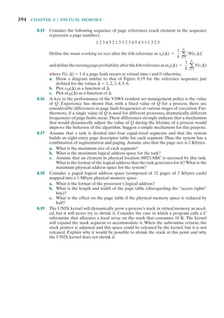


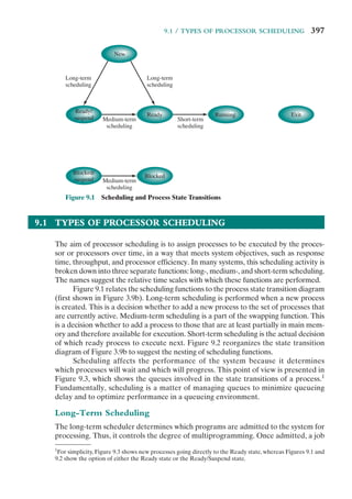


![402 CHAPTER 9 / UNIPROCESSOR SCHEDULING
response time may require a scheduling algorithm that switches between processes
frequently. This increases the overhead of the system, reducing throughput. Thus,
the design of a scheduling policy involves compromising among competing require-
ments; the relative weights given the various requirements will depend on the
nature and intended use of the system.
In most interactive operating systems, whether single user or time shared, ade-
quate response time is the critical requirement. Because of the importance of this
requirement, and because the definition of adequacy will vary from one application
to another, the topic is explored further in Appendix G.
The Use of Priorities
In many systems, each process is assigned a priority and the scheduler will always
choose a process of higher priority over one of lower priority. Figure 9.4 illustrates the
use of priorities. For clarity, the queueing diagram is simplified, ignoring the existence
of multiple blocked queues and of suspended states (compare Figure 3.8a). Instead
of a single ready queue, we provide a set of queues, in descending order of priority:
RQ0, RQ1, . . . , RQn, with priority[RQi] > priority[RQj] for i> j.3
When a scheduling
selection is to be made, the scheduler will start at the highest-priority ready queue
(RQ0). If there are one or more processes in the queue, a process is selected using
some scheduling policy. If RQ0 is empty, then RQ1 is examined, and so on.
Event wait
Event
occurs
Preemption
Dispatch
Release
RQ0
RQ1
RQn
Admit
Processor
Blocked queue
Figure 9.4 Priority Queueing
3
In UNIX and many other systems, larger priority values represent lower priority processes; unless
otherwise stated we follow that convention. Some systems, such as Windows, use the opposite convention:
a higher number means a higher priority.](https://image.slidesharecdn.com/williamstallingsoperatingsystemsinter-230528124001-c4cbce35/85/William_Stallings_Operating_SystemsInter-pdf-424-320.jpg)
![9.2 / SCHEDULING ALGORITHMS 403
One problem with a pure priority scheduling scheme is that lower-priority
processes may suffer starvation. This will happen if there is always a steady supply
of higher-priority ready processes. If this behavior is not desirable, the priority of a
process can change with its age or execution history. We will give one example of
this subsequently.
Alternative Scheduling Policies
Table 9.3 presents some summary information about the various scheduling poli-
cies that are examined in this subsection. The selection function determines which
process, among ready processes, is selected next for execution. The function may
be based on priority, resource requirements, or the execution characteristics of the
process. In the latter case, three quantities are significant:
w = time spent in system so far, waiting
e = time spent in execution so far
s = total service time required by the process,including e;generally,this quantity
must be estimated or supplied by the user
For example, the selection function max[w] indicates an FCFS discipline.
Table 9.3 Characteristics of Various Scheduling Policies
FCFS
Round
Robin
SPN SRT HRRN Feedback
Selection
Function
max[w] constant min[s] min[s – e] maxa
w + s
s
b (see text)
Decision
Mode
Non-
preemptive
Preemptive
(at time
quantum)
Non-
preemptive
Preemptive
(at arrival)
Non-
preemptive
Preemptive
(at time
quantum)
Throughput
Not
emphasized
May be low
if quantum
is too small
High High High
Not
emphasized
Response
Time
May be high,
especially if
there is
a large
variance
in process
execution
times
Provides
good
response
time for
short
processes
Provides
good
response
time for
short
processes
Provides
good
response
time
Provides
good
response
time
Not
emphasized
Overhead Minimum Minimum Can be high Can be high Can be high Can be high
Effect on
Processes
Penalizes
short
processes;
penalizes
I/O bound
processes
Fair
treatment
Penalizes
long
processes
Penalizes
long
processes
Good
balance
May favor
I/O bound
processes
Starvation No No Possible Possible No Possible](https://image.slidesharecdn.com/williamstallingsoperatingsystemsinter-230528124001-c4cbce35/85/William_Stallings_Operating_SystemsInter-pdf-425-320.jpg)


![9.2 / SCHEDULING ALGORITHMS 407
FIRST-COME-FIRST-SERVED The simplest scheduling policy is first-come-first-
served (FCFS), also known as first-in-first-out (FIFO) or a strict queueing scheme.
As each process becomes ready, it joins the ready queue. When the currently
running process ceases to execute, the process that has been in the ready queue the
longest is selected for running.
FCFS performs much better for long processes than short ones. Consider the
following example, based on one in [FINK88]:
Process
Arrival
Time
Service
Time (Ts) Start Time
Finish
Time
Turnaround
Time (Tr) Tr /Ts
W 0 1 0 1 1 1
X 1 100 1 101 100 1
Y 2 1 101 102 100 100
Z 3 100 102 202 199 1.99
Mean 100 26
The normalized turnaround time for process Y is way out of line compared to
the other processes: the total time that it is in the system is 100 times the required
processing time. This will happen whenever a short process arrives just after a long
process. On the other hand, even in this extreme example, long processes do not
fare poorly. Process Z has a turnaround time that is almost double that of Y, but its
normalized residence time is under 2.0.
Another difficulty with FCFS is that it tends to favor processor-bound processes
over I/O-bound processes. Consider that there is a collection of processes, one of
which mostly uses the processor (processor bound) and a number of which favor I/O
(I/O bound). When a processor-bound process is running, all of the I/O bound proc-
esses must wait. Some of these may be in I/O queues (blocked state) but may move
back to the ready queue while the processor-bound process is executing. At this point,
most or all of the I/O devices may be idle, even though there is potentially work for
them to do. When the currently running process leaves the Running state, the ready
I/O-bound processes quickly move through the Running state and become blocked on
I/O events. If the processor-bound process is also blocked, the processor becomes idle.
Thus, FCFS may result in inefficient use of both the processor and the I/O devices.
FCFS is not an attractive alternative on its own for a uniprocessor system.
However, it is often combined with a priority scheme to provide an effective sched-
uler. Thus, the scheduler may maintain a number of queues, one for each priority
level, and dispatch within each queue on a first-come-first-served basis. We see one
example of such a system later, in our discussion of feedback scheduling.
ROUND ROBIN A straightforward way to reduce the penalty that short jobs suffer
with FCFS is to use preemption based on a clock. The simplest such policy is round
robin. A clock interrupt is generated at periodic intervals. When the interrupt
occurs, the currently running process is placed in the ready queue, and the next
ready job is selected on a FCFS basis. This technique is also known as time slicing,
because each process is given a slice of time before being preempted.](https://image.slidesharecdn.com/williamstallingsoperatingsystemsinter-230528124001-c4cbce35/85/William_Stallings_Operating_SystemsInter-pdf-429-320.jpg)

![9.2 / SCHEDULING ALGORITHMS 409
treatment of processor-bound and I/O-bound processes. Generally, an I/O-bound
process has a shorter processor burst (amount of time spent executing between I/O
operations) than a processor-bound process. If there is a mix of processor-bound
and I/O-bound processes, then the following will happen: An I/O-bound process
uses a processor for a short period and then is blocked for I/O; it waits for the
I/O operation to complete and then joins the ready queue. On the other hand, a
processor-bound process generally uses a complete time quantum while execut-
ing and immediately returns to the ready queue. Thus, processor-bound processes
tend to receive an unfair portion of processor time, which results in poor perform-
ance for I/O-bound processes, inefficient use of I/O devices, and an increase in the
variance of response time.
[HALD91] suggests a refinement to round robin that he refers to as a virtual
round robin (VRR) and that avoids this unfairness. Figure 9.7 illustrates the scheme.
New processes arrive and join the ready queue, which is managed on an FCFS basis.
When a running process times out, it is returned to the ready queue. When a process
is blocked for I/O, it joins an I/O queue. So far, this is as usual. The new feature is
an FCFS auxiliary queue to which processes are moved after being released from
an I/O block. When a dispatching decision is to be made, processes in the auxil-
iary queue get preference over those in the main ready queue. When a process is
dispatched from the auxiliary queue, it runs no longer than a time equal to the basic
time quantum minus the total time spent running since it was last selected from the
I/O 1 wait
I/O 2 wait
I/O n wait
Dispatch
Timeout
Release
Ready queue
Admit
Processor
I/O 1 queue
Auxiliary queue
I/O 1
occurs
I/O 2
occurs
I/O n
occurs
I/O 2 queue
I/O n queue
Figure 9.7 Queueing Diagram for Virtual Round-Robin Scheduler](https://image.slidesharecdn.com/williamstallingsoperatingsystemsinter-230528124001-c4cbce35/85/William_Stallings_Operating_SystemsInter-pdf-431-320.jpg)


![418 CHAPTER 9 / UNIPROCESSOR SCHEDULING
Figure 9.13 shows the same analysis for the lower-priority, longer processes.
As expected, such processes suffer a performance degradation under priority
scheduling.
SIMULATION MODELING Some of the difficulties of analytic modeling are
overcome by using discrete-event simulation, which allows a wide range of policies
to be modeled. The disadvantage of simulation is that the results for a given “run”
only apply to that particular collection of processes under that particular set of
assumptions. Nevertheless, useful insights can be gained.
The results of one such study are reported in [FINK88]. The simulation
involved 50,000 processes with an arrival rate of ⫽ 0.8 and an average service time
of Ts ⫽ 1. Thus, the assumption is that the processor utilization is r = Ts = 0.8.
Note, therefore, that we are only measuring one utilization point.
To present the results, processes are grouped into service-time percentiles,
each of which has 500 processes. Thus, the 500 processes with the shortest service
time are in the first percentile; with these eliminated, the 500 remaining processes
with the shortest service time are in the second percentile; and so on. This allows
us to view the effect of various policies on processes as a function of the length of
the process.
Figure 9.14 shows the normalized turnaround time, and Figure 9.15 shows
the average waiting time. Looking at the turnaround time, we can see that the
performance of FCFS is very unfavorable, with one-third of the processes having
0.1
1
2
3
4
5
6
7
8
9
10
0.2 0.3 0.4 0.5
2 priority classes
1 ⫽ 2
ts2 ⫽ 5 ⫻ ts1
Normalized
response
time
(T
r2
/T
s2
)
0.6 0.7 0.8 0.9 1.0
Priority
Priority
with preemption
No priority
Utilization ( )
Figure 9.13 Normalized Response Time for Longer Processes](https://image.slidesharecdn.com/williamstallingsoperatingsystemsinter-230528124001-c4cbce35/85/William_Stallings_Operating_SystemsInter-pdf-440-320.jpg)

![420 CHAPTER 9 / UNIPROCESSOR SCHEDULING
a normalized turnaround time greater than 10 times the service time; furthermore,
these are the shortest processes. On the other hand, the absolute waiting time is
uniform, as is to be expected because scheduling is independent of service time.
The figures show round robin using a quantum of one time unit. Except for the
shortest processes, which execute in less than one quantum, round robin yields
a normalized turnaround time of about five for all processes, treating all fairly.
Shortest process next performs better than round robin, except for the shortest
processes. Shortest remaining time, the preemptive version of SPN, performs bet-
ter than SPN except for the longest 7% of all processes. We have seen that, among
nonpreemptive policies, FCFS favors long processes and SPN favors short ones.
Highest response ratio next is intended to be a compromise between these two
effects, and this is indeed confirmed in the figures. Finally, the figure shows feed-
back scheduling with fixed, uniform quanta in each priority queue. As expected,
FB performs quite well for short processes.
Fair-Share Scheduling
All of the scheduling algorithms discussed so far treat the collection of ready
processes as a single pool of processes from which to select the next running process.
This pool may be broken down by priority but is otherwise homogeneous.
However, in a multiuser system, if individual user applications or jobs may be
organized as multiple processes (or threads), then there is a structure to the collec-
tion of processes that is not recognized by a traditional scheduler. From the user’s
point of view, the concern is not how a particular process performs but rather how
his or her set of processes, which constitute a single application, performs. Thus, it
would be attractive to make scheduling decisions on the basis of these process sets.
This approach is generally known as fair-share scheduling. Further, the concept can
be extended to groups of users, even if each user is represented by a single process.
For example, in a time-sharing system, we might wish to consider all of the users
from a given department to be members of the same group. Scheduling decisions
could then be made that attempt to give each group similar service. Thus, if a large
number of people from one department log onto the system, we would like to see
response time degradation primarily affect members of that department rather than
users from other departments.
The term fair share indicates the philosophy behind such a scheduler. Each
user is assigned a weighting of some sort that defines that user’s share of system
resources as a fraction of the total usage of those resources. In particular, each
user is assigned a share of the processor. Such a scheme should operate in a more
or less linear fashion, so that if user A has twice the weighting of user B, then in
the long run, user A should be able to do twice as much work as user B. The objec-
tive of a fair-share scheduler is to monitor usage to give fewer resources to users
who have had more than their fair share and more to those who have had less than
their fair share.
A number of proposals have been made for fair-share schedulers [HENR84,
KAY88, WOOD86]. In this section, we describe the scheme proposed in [HENR84]
and implemented on a number of UNIX systems. The scheme is simply referred to
as the fair-share scheduler (FSS). FSS considers the execution history of a related](https://image.slidesharecdn.com/williamstallingsoperatingsystemsinter-230528124001-c4cbce35/85/William_Stallings_Operating_SystemsInter-pdf-442-320.jpg)


![9.5 / RECOMMENDED READING 425
A variety of criteria are used in designing the short-term scheduler. Some of
these criteria relate to the behavior of the system as perceived by the individual user
(user oriented), while others view the total effectiveness of the system in meeting
the needs of all users (system oriented). Some of the criteria relate specifically to
quantitative measures of performance, while others are more qualitative in nature.
From a user’s point of view, response time is generally the most important char-
acteristic of a system, while from a system point of view, throughput or processor
utilization is important.
A variety of algorithms have been developed for making the short-term sched-
uling decision among all ready processes:
• First-come-first-served: Select the process that has been waiting the longest
for service.
• Round robin: Use time slicing to limit any running process to a short burst of
processor time, and rotate among all ready processes.
• Shortest process next: Select the process with the shortest expected processing
time, and do not preempt the process.
• Shortest remaining time: Select the process with the shortest expected remain-
ing process time. A process may be preempted when another process becomes
ready.
• Highest response ratio next: Base the scheduling decision on an estimate of
normalized turnaround time.
• Feedback: Establish a set of scheduling queues and allocate processes to
queues based on execution history and other criteria.
The choice of scheduling algorithm will depend on expected performance and
on implementation complexity.
9.5 RECOMMENDED READING
Virtually every textbook on operating systems covers scheduling. Rigorous
queueing analyses of various scheduling policies are presented in [KLEI04] and
[CONW67]. [DOWD93] provides an instructive performance analysis of various
scheduling algorithms.
CONW67 Conway, R., Maxwell, W., and Miller, L. Theory of Scheduling. Reading,
MA: Addison-Wesley, 1967. Reprinted by Dover Publications, 2003.
DOWD93 Dowdy, L., and Lowery, C. P.S. to Operating Systems. Upper Saddle River,
NJ: Prentice Hall, 1993.
KLEI04 Kleinrock, L. Queuing Systems, Volume Three: Computer Applications. New
York: Wiley, 2004.](https://image.slidesharecdn.com/williamstallingsoperatingsystemsinter-230528124001-c4cbce35/85/William_Stallings_Operating_SystemsInter-pdf-447-320.jpg)

![9.6 / KEY TERMS, REVIEW QUESTIONS, AND PROBLEMS 427
Example for FCFS (1 unit = 10 ms):
P1 P1 P1 P1 P1 P2 P2 P3 P3 P3 P3 P3 P3 P3 P3 P3 P3 P4 P4 P4 P4
0 1 2 3 4 5 6 7 8 9 10 11 12 13 14 15 16 17 18 19 20
b. What is the average waiting time of the above scheduling policies?
9.2 Consider the following set of processes:
Process Arrival Time Processing Time
A 0 3
B 1 5
C 3 2
D 9 5
E 12 5
Perform the same analysis as depicted in Table 9.5 and Figure 9.5 for this set.
9.3 Prove that, among nonpreemptive scheduling algorithms, SPN provides the minimum
average waiting time for a batch of jobs that arrive at the same time.Assume that the
scheduler must always execute a task if one is available.
9.4 Assume the following burst-time pattern for a process: 6, 4, 6, 4, 13, 13, 13, and assume
that the initial guess is 10. Produce a plot similar to those of Figure 9.9.
9.5 Consider the following pair of equations as an alternative to Equation (9.3):
Sn+1 = aTn + (1 - a)Sn
Xn+1 = min[Ubound, max[Lbound, (bSn+1)]]
where Ubound and Lbound are prechosen upper and lower bounds on the estimated
value of T.The value of Xn + 1 is used in the shortest-process-next algorithm, instead of
the value of Sn + 1.What functions do a and b perform, and what is the effect of higher
and lower values on each?
9.6 In the bottom example in Figure 9.5, process A runs for two time units before control
is passed to process B.Another plausible scenario would be that A runs for three time
units before control is passed to process B. What policy differences in the feedback-
scheduling algorithm would account for the two different scenarios?
9.7 In a nonpreemptive uniprocessor system, the ready queue contains three jobs at time
t immediately after the completion of a job. These jobs arrived at times t1, t2, and t3
with estimated execution times of r1, r2, and r3, respectively. Figure 9.18 shows the
linear increase of their response ratios over time. Use this example to find a variant
of response ratio scheduling, known as minimax response ratio scheduling, that mini-
mizes the maximum response ratio for a given batch of jobs ignoring further arrivals.
(Hint: Decide, first, which job to schedule as the last one.)
9.8 Prove that the minimax response ratio algorithm of the preceding problem minimizes
the maximum response ratio for a given batch of jobs. (Hint: Focus attention on the
job that will achieve the highest response ratio and all jobs executed before it. Con-
sider the same subset of jobs scheduled in any other order and observe the response
ratio of the job that is executed as the last one among them. Notice that this subset
may now be mixed with other jobs from the total set.)
9.9 Define residence time Tr as the average total time a process spends waiting and being
served. Show that for FIFO, with mean service time Ts, we have Tr = Ts/(1 – r), where
r is utilization.](https://image.slidesharecdn.com/williamstallingsoperatingsystemsinter-230528124001-c4cbce35/85/William_Stallings_Operating_SystemsInter-pdf-449-320.jpg)


![432 CHAPTER 10 / MULTIPROCESSOR AND REAL-TIME SCHEDULING
Our concern in this section is with the last category, and specifically with issues
relating to scheduling.
Granularity
A good way of characterizing multiprocessors and placing them in context with
other architectures is to consider the synchronization granularity, or frequency of
synchronization, between processes in a system. We can distinguish five catego-
ries of parallelism that differ in the degree of granularity. These are summarized in
Table 10.1, which is adapted from [GEHR87] and [WOOD89].
INDEPENDENT PARALLELISM With independent parallelism, there is no explicit
synchronization among processes. Each represents a separate, independent
application or job. A typical use of this type of parallelism is in a time-sharing system.
Each user is performing a particular application such as word processing or using a
spreadsheet. The multiprocessor provides the same service as a multiprogrammed
uniprocessor. Because more than one processor is available, average response time
to the users will be less.
It is possible to achieve a similar performance gain by providing each user with
a personal computer or workstation. If any files or information are to be shared,
then the individual systems must be hooked together into a distributed system sup-
ported by a network. This approach is examined in Chapter 16. On the other hand,
a single, multiprocessor shared system in many instances is more cost-effective than
a distributed system, allowing economies of scale in disks and other peripherals.
COARSE AND VERY COARSE-GRAINED PARALLELISM With coarse and very coarse-
grained parallelism, there is synchronization among processes, but at a very gross
level. This kind of situation is easily handled as a set of concurrent processes running
on a multiprogrammed uniprocessor and can be supported on a multiprocessor with
little or no change to user software.
A simple example of an application that can exploit the existence of a multi-
processor is given in [WOOD89]. The authors have developed a program that takes
a specification of files needing recompilation to rebuild a piece of software and
determines which of these compiles (usually all of them) can be run simultaneously.
Table 10.1 Synchronization Granularity and Processes
Grain Size Description
Synchronization
Interval (Instructions)
Fine Parallelism inherent in a single instruction stream 6 20
Medium Parallel processing or multitasking within a single application 20–200
Coarse Multiprocessing of concurrent processes in a
multiprogramming environment
200–2,000
Very Coarse Distributed processing across network nodes to form a single
computing environment
2,000–1M
Independent Multiple unrelated processes Not applicable](https://image.slidesharecdn.com/williamstallingsoperatingsystemsinter-230528124001-c4cbce35/85/William_Stallings_Operating_SystemsInter-pdf-454-320.jpg)


![10.1 / MULTIPROCESSOR SCHEDULING 435
In the traditional multiprocessor, which is dealing with coarse-grained or
independent synchronization granularity (see Table 10.1), it is clear that each individ-
ual processor should be able to switch among a number of processes to achieve high
utilization and therefore better performance. However, for medium-grained applica-
tions running on a multiprocessor with many processors, the situation is less clear.
When many processors are available, it is no longer paramount that every single proc-
essor be busy as much as possible. Rather, we are concerned to provide the best per-
formance, on average, for the applications. An application that consists of a number
of threads may run poorly unless all of its threads are available to run simultaneously.
PROCESS DISPATCHING The final design issue related to multiprocessor scheduling
is the actual selection of a process to run. We have seen that, on a multiprogrammed
uniprocessor, the use of priorities or of sophisticated scheduling algorithms based
on past usage may improve performance over a simple-minded first-come-first-
served strategy. When we consider multiprocessors, these complexities may be
unnecessary or even counterproductive, and a simpler approach may be more
effective with less overhead. In the case of thread scheduling, new issues come into
play that may be more important than priorities or execution histories. We address
each of these topics in turn.
Process Scheduling
In most traditional multiprocessor systems, processes are not dedicated to proces-
sors. Rather there is a single queue for all processors, or if some sort of priority
scheme is used, there are multiple queues based on priority, all feeding into the
common pool of processors. In any case, we can view the system as being a multi-
server queueing architecture.
Consider the case of a dual-processor system in which each processor of the
dual-processor system has half the processing rate of a processor in the single-processor
system. [SAUE81] reports a queueing analysis that compares FCFS scheduling to round
robin and to shortest remaining time. The study is concerned with process service time,
which measures the amount of processor time a process needs, either for a total job or
the amount of time needed each time the process is ready to use the processor. In the
case of round robin, it is assumed that the time quantum is large compared to context-
switching overhead and small compared to mean service time. The results depend on
the variability that is seen in service times. A common measure of variability is the
coefficient of variation, Cs.1
A value of Cs ⫽ 0 corresponds to the case where there is
no variability: the service times of all processes are equal. Increasing values of Cs corre-
spond to increasing variability among the service times. That is, the larger the value of
Cs, the more widely do the values of the service times vary. Values of Cs of 5 or more
are not unusual for processor service time distributions.
Figure 10.1a compares round-robin throughput to FCFS throughput as a func-
tion of Css. Note that the difference in scheduling algorithms is much smaller in the
dual-processor case. With two processors, a single process with long service time is
1
The value of Cs is calculated as s/Ts, where s is the standard deviation of service time and Ts is the
mean service time. For a further explanation of Cs, see the discussion in Chapter 20.](https://image.slidesharecdn.com/williamstallingsoperatingsystemsinter-230528124001-c4cbce35/85/William_Stallings_Operating_SystemsInter-pdf-457-320.jpg)
![436 CHAPTER 10 / MULTIPROCESSOR AND REAL-TIME SCHEDULING
much less disruptive in the FCFS case; other processes can use the other processor.
Similar results are shown in Figure 10.1b.
The study in [SAUE81] repeated this analysis under a number of assumptions
about degree of multiprogramming, mix of I/O-bound versus CPU-bound proc-
esses, and the use of priorities. The general conclusion is that the specific scheduling
discipline is much less important with two processors than with one. It should be
evident that this conclusion is even stronger as the number of processors increases.
Thus, a simple FCFS discipline or the use of FCFS within a static priority scheme
may suffice for a multiple-processor system.
Single
processor
Dual
processor
SRT
to
FCFS
throughput
ratio
0
1.00
1.05
1.10
1.15
1.20
1.25
1 2 3 4 5
Coefficient of variation
(a) Comparison of RR and FCFS
Coefficient of variation
(b) Comparison of SRT and FCFS
0 1 2
Single
processor
Dual
processor
0.98
RR
to
FCFS
throughput
ratio
3 4 5
1.00
1.05
1.10
1.15
Figure 10.1 Comparison of Scheduling Performance for One
and Two Processors](https://image.slidesharecdn.com/williamstallingsoperatingsystemsinter-230528124001-c4cbce35/85/William_Stallings_Operating_SystemsInter-pdf-458-320.jpg)
![10.1 / MULTIPROCESSOR SCHEDULING 437
Thread Scheduling
As we have seen, with threads, the concept of execution is separated from the rest
of the definition of a process. An application can be implemented as a set of threads
that cooperate and execute concurrently in the same address space.
On a uniprocessor, threads can be used as a program structuring aid and to
overlap I/O with processing. Because of the minimal penalty in doing a thread
switch compared to a process switch, these benefits are realized with little cost.
However, the full power of threads becomes evident in a multiprocessor system. In
this environment, threads can be used to exploit true parallelism in an application.
If the various threads of an application are simultaneously run on separate proces-
sors, dramatic gains in performance are possible. However, it can be shown that
for applications that require significant interaction among threads (medium-grain
parallelism), small differences in thread management and scheduling can have a
significant performance impact [ANDE89].
Among the many proposals for multiprocessor thread scheduling and proces-
sor assignment, four general approaches stand out:
• Load sharing: Processes are not assigned to a particular processor. A global
queue of ready threads is maintained, and each processor, when idle, selects a
thread from the queue. The term load sharing is used to distinguish this strat-
egy from load-balancing schemes in which work is allocated on a more perma-
nent basis (e.g., see [FEIT90a]).2
• Gang scheduling: A set of related threads is scheduled to run on a set of proc-
essors at the same time, on a one-to-one basis.
• Dedicated processor assignment: This is the opposite of the load-sharing
approach and provides implicit scheduling defined by the assignment of
threads to processors. Each program, for the duration of its execution, is allo-
cated a number of processors equal to the number of threads in the program.
When the program terminates, the processors return to the general pool for
possible allocation to another program.
• Dynamic scheduling: The number of threads in a process can be altered during
the course of execution.
LOAD SHARING Load sharing is perhaps the simplest approach and the one that
carries over most directly from a uniprocessor environment. It has several advantages:
• The load is distributed evenly across the processors, assuring that no processor
is idle while work is available to do.
• No centralized scheduler is required; when a processor is available, the
scheduling routine of the operating system is run on that processor to select
the next thread.
2
Some of the literature on this topic refers to this approach as self-scheduling, because each processor
schedules itself without regard to other processors. However, this term is also used in the literature to
refer to programs written in a language that allows the programmer to specify the scheduling (e.g., see
[FOST91]).](https://image.slidesharecdn.com/williamstallingsoperatingsystemsinter-230528124001-c4cbce35/85/William_Stallings_Operating_SystemsInter-pdf-459-320.jpg)
![438 CHAPTER 10 / MULTIPROCESSOR AND REAL-TIME SCHEDULING
• The global queue can be organized and accessed using any of the schemes dis-
cussed in Chapter 9, including priority-based schemes and schemes that con-
sider execution history or anticipated processing demands.
[LEUT90] analyzes three different versions of load sharing:
• First-come-first-served (FCFS): When a job arrives, each of its threads is
placed consecutively at the end of the shared queue. When a processor be-
comes idle, it picks the next ready thread, which it executes until completion
or blocking.
• Smallest number of threads first: The shared ready queue is organized as a pri-
ority queue, with highest priority given to threads from jobs with the smallest
number of unscheduled threads. Jobs of equal priority are ordered according
to which job arrives first. As with FCFS, a scheduled thread is run to comple-
tion or blocking.
• Preemptive smallest number of threads first: Highest priority is given to jobs
with the smallest number of unscheduled threads. An arriving job with a
smaller](https://image.slidesharecdn.com/williamstallingsoperatingsystemsinter-230528124001-c4cbce35/85/William_Stallings_Operating_SystemsInter-pdf-460-320.jpg)