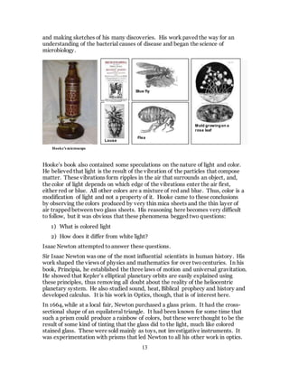
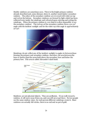
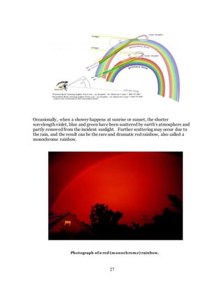
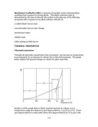
1. The document discusses the history and evolution of optics from ancient times to the 11th century CE. It describes how early civilizations like the Greeks, Chinese, and Phoenicians made early observations and experiments with light, lenses, mirrors, and vision.
2. The work of the ancient Greek philosophers such as Euclid, Ptolemy, and Aristotle helped develop early theories of light, but it was not until the 11th century Arab scholar Ibn al-Haytham (Alhazen) that many modern theories of vision and optics began to take hold. Through experiments with lenses, mirrors, and the camera obscura, Alhazen helped debunk earlier theories and establish that light travels in straight lines

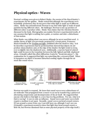
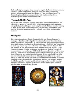
![20
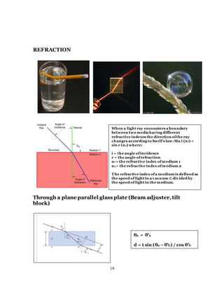
Through a plane wedged glass plate
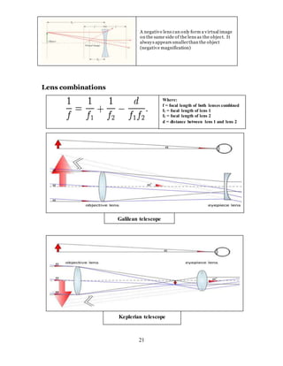
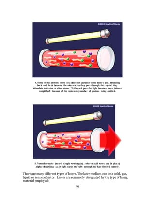
Through lenses
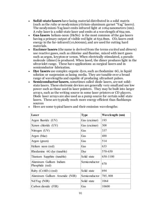
.
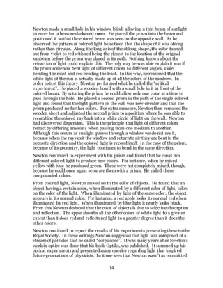
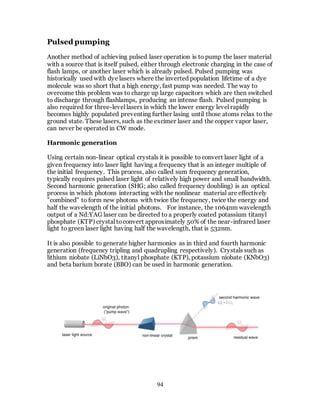
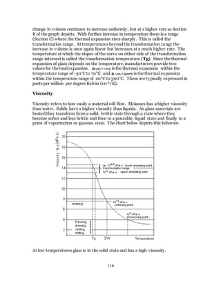
Lensmaker’s formula
1/f = (n-1) [1/R1 – 1/R2 + (n-1)d/nR1R2]
where
f is the focal length ofthe lens,
n is the refractiveindex ofthe lens
material,
R1 is the radius ofcurvatureofthe
lens surface closest to the light
source,
R2 is the radius of curvatureofthe
lens surface farthest from the light
source,and
d is the center thicknessofthe lens
(the distance along the lens axis
between the two surface vertices).
Light from an object that is at a distance
beyondthe lens focal length forms a real
image on the side of the lens opposite the
object. Magnification (reduction) ofthe
image is S2 / S1. For an objectat infinity (or
very far away from the lens) the image will be
a small focused spot.
Light from an object that is at a distance less
than the lens focal length forms a virtual
image on the same side of the lens as the
object. Magnification ofthe image is S2 / S1.
This is the principle ofa magnifying glass.](https://image.slidesharecdn.com/112ccee8-35a6-4aa6-9738-adeb62df7591-150902162927-lva1-app6891/85/What-is-optic1-20-320.jpg)


![[Final dr. abdul latif] ibn al haytham](https://cdn.slidesharecdn.com/ss_thumbnails/finaldr-160128195018-thumbnail.jpg?width=640&height=640&fit=bounds)