This document discusses VoLTE and ViLTE services over 4G mobile networks. It covers:
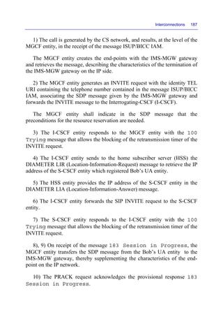
- The network architecture of EPS (Evolved Packet System) and IMS (IP Multimedia Subsystem) networks, including functional components and protocols.
- Signaling protocols used in the EPS network (NAS, RRC, S1-AP, GTPv2-C) and IMS network (SIP, SDP, DIAMETER).
- Basic network procedures like attachment, registration, session establishment and termination for VoLTE and ViLTE calls.


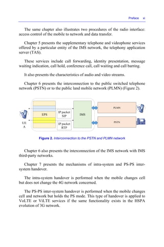


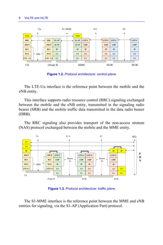


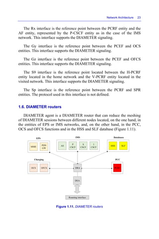


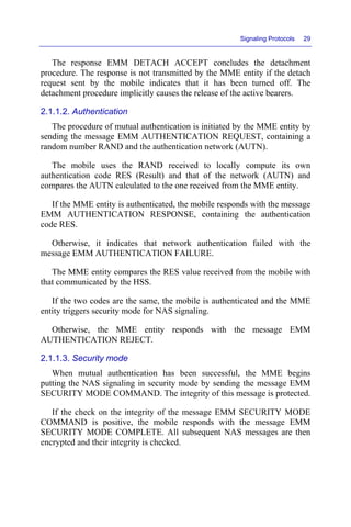


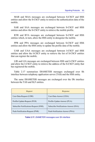


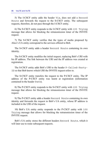


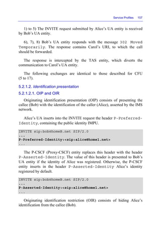
![Radio Interface Procedures 133
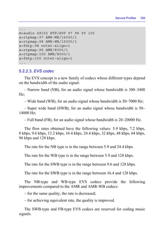
to avoid processing this channel every millisecond and in this way to
preserve the consumption of its battery (Figure 4.11).
Figure 4.11. DRX function For a color version of
the figure, see www.iste.co.uk/perez/volte.zip
An inactivity timer drx-Inactivity Timer of the DRX function is triggered
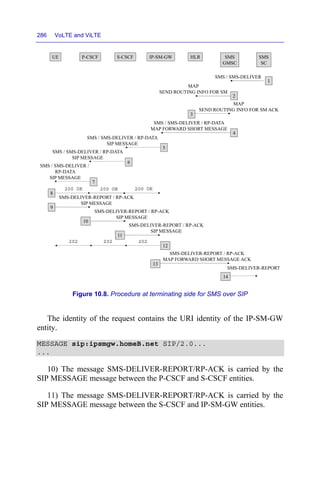
when the mobile receives data on the PDCCH physical channel.
This timer is reinitialized each time that the mobile receives data on the
PDCCH physical channel.
When the timer drx-Inactivity Timer expires, the mobile starts an optional
period for the short cycle corresponding to the timer drxShort Cycle Timer.
During the short cycle, the mobile analyzes the PDCCH physical channel
in a duration corresponding to the timer onDurationTimer.
During the short cycle, the triggering of the active period is provided by
the following formula:
[(SFN * 10) + (sub-frame number)] modulo (shortDRX-Cycle) =
(drxStartOffset) modulo (shortDRX-Cycle)
When the timer drxShort Cycle Timer expires, the mobile starts the long
cycle period for which the triggering of the active period is provided by the
following formula:
[(SFN * 10) + (sub-frame number)] modulo (longDRX-Cycle) =
drxStartOffset
The parameter configuration of the DRX function is indicated in the RRC
messages of establishment or re-establishment of the connection.
drx-InactivityTimer
shortDRX-Cycle
drxShortCycleTimer
longDRX-Cycle
onDurationTimer onDurationTimer](https://image.slidesharecdn.com/volteandvilte-221117171109-c777b620/85/VoLTE-and-ViLTE-pdf-163-320.jpg)

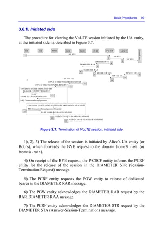
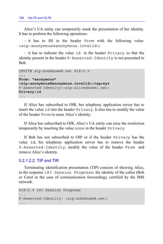
![Radio Interface Procedures 135
(10 * SFN + sub-frame) = [(10 * SFNstart time + subframestart time) +
N * semiPersistSchedIntervalDL] modulo 10240
The SFN start time and sub frame start time parameters correspond to the
values of the frame and sub-frame number when the SPS function has been
activated.
The semiPersistSchedIntervalDL parameter corresponds to the allocation
periodicity of resources for the downlink.
When the SPS function has been activated for the uplink, the sub-frame
allocation of the PUSCH physical channel corresponds to the following
formula:
(10 * SFN + sub-frame) = [(10 * SFNstart time + subframestart time) +
N * semiPersistSchedIntervalUL + Subframe_Offset * (N modulo 2)]
modulo 10240
The semiPersistSchedIntervalUL parameter corresponds to the allocation
periodicity of resources for the uplink.
The Subframe_Offset parameter is optional and its value is equal to
ZERO for the FDD mode and is indicated in Table 4.6 for the TDD mode.
Configuration of the
sub-frame
Number of the subf-rame during
the SPS activation
Sub-frame_Offset
0 sans objet 0
1
2 and 7 1
3 and 8 -1
2
2 5
7 -5
3
2 and 3 1
4 -2
4
2 1
3 -1
5 sans objet 0
6 sans objet 0
Table 4.6. Value of optional parameter Subframe_Offset](https://image.slidesharecdn.com/volteandvilte-221117171109-c777b620/85/VoLTE-and-ViLTE-pdf-165-320.jpg)


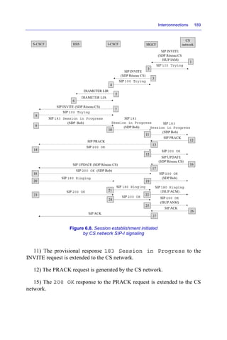
![Service Profiles 171
– if the UA entity responsible for the conversational video conference
removes the video stream, the IMS network may decide to convert
conversational video conference in an audio conference for all participants.
5.3.2. Video flow
The SDP message contains the types of video codecs proposed by the
caller and the codec selected by the callee, among the following codecs list:
– H.264 codec, with constrained baseline profile (CBP), level 1.2;
– H.265 with main profile (MP) level 3.1 main tier.
5.3.2.1. H.264 codec
H.264 profile is identified by the parameter profile-level-id in
the SDP offer.
The maximum image size (number of pixels) and the maximum number
of frames per second for the CBP profile level 1.2 can take several values:
– size 176 × 144, 60.6 frame/s;
– size 320 × 240, 20 frame/s;
– size 352 × 288, 15.2 frame/s.
Several actual sizes of the image can be negotiated and are identified by
the parameter a = imageattr in the SDP offer.
The maximum rate supported by the profile is equal to 384 kbps. The
reserved actual reserved is indicated by the parameter b = AS in the SDP
offer.
...
m=video 49154 RTP/AVP 99
b=AS:315
a=rtpmap:99 H264/90000
a=fmtp:99 profile-level-id=42e00c
a=imageattr:99 send [x=176,y=144] [x=224,y=176]
[x=272,y=224] [x=320,y=240] recv [x=176,y=144]
[x=224,y=176] [x=272,y=224] [x=320,y=240]
...](https://image.slidesharecdn.com/volteandvilte-221117171109-c777b620/85/VoLTE-and-ViLTE-pdf-201-320.jpg)
![172 VoLTE and ViLTE
5.3.2.2. H.265 codec
The H.265 codec presents the following improvements compared to
H.264 codec:
– for the same quality, the rate is decreased;
– for an equivalent rate, the quality is improved.
The maximum image size (number of pixels) and the maximum number
of frames per second for the MP profile level 3.1 main tier can take several
values:
– size 720 × 576, 75 frame/s;
– size 960 × 540, 60 frame/s;
– size 1280 × 720, 33.7 frame/s.
In the following example, the mobile is equipped with a 5-inch screen
which supports an 848 × 480 frame size and 25 frames per second.
The SDP offer provides H.265 codec, H.264 level 3.1 for the frame size
848 × 480 and H.264 level 1.2 for the frame size 320 × 240.
The required rate is equal to 690 kbps for a H.264 level 3.1 and 540 kb/s
for the H.265 codec. The rate indicated by the parameter b = AS is the
maximum rate.
...
m=video 49154 RTP/AVP 98 97 100 99
b=AS:690
a=rtpmap:100 H264/90000
a=fmtp:100 profile-level-id=42e01f
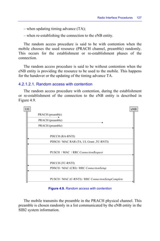
a=imageattr:100 send [x=848,y=480] recv [x=848,y=480]
a=rtpmap:99 H264/90000
a=fmtp:99 profile-level-id=42e01f
a=imageattr:99 send [x=320,y=240] recv [x=320,y=240]
a=rtpmap:98 H265/90000
a=fmtp:98 profile-id=1; level-id=93
a=imageattr:98 send [x=848,y=480] recv [x=848,y=480]
a=rtpmap:97 H265/90000
a=fmtp:97 profile-id=1; level-id=93
a=imageattr:97 send [x=320,y=240] recv [x=320,y=240]
...](https://image.slidesharecdn.com/volteandvilte-221117171109-c777b620/85/VoLTE-and-ViLTE-pdf-202-320.jpg)


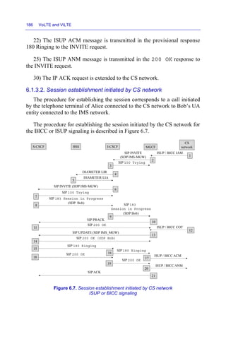


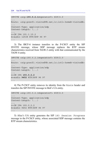


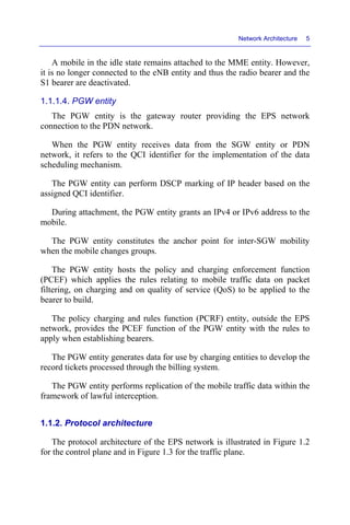
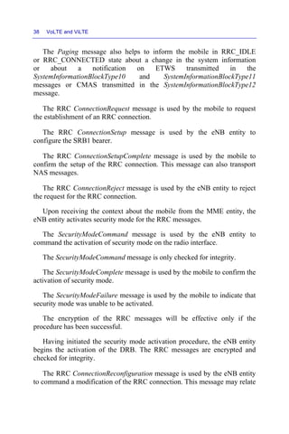
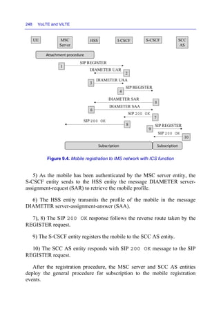
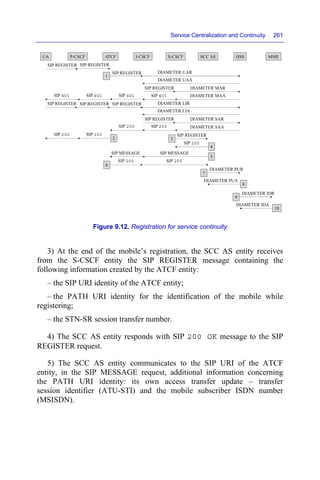
![Service Centralization and Continuity 247
The SIP URI (Uniform Resource Identifier) of the REGISTER request is
derived from the mobile country code (MCC) and the mobile network code
(MNC).
The temporary public identity of the headers From and To is derived
from the international mobile subscriber identity (IMSI).
The private identity in the Authorization header is also derived from
the IMSI private identity.
The Contact header contains the parameter + g.3gpp.ics
indicating that the MSC server entity implements the ICS service.
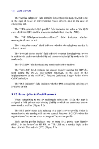
REGISTER sip:ics.mnc01.mcc208.3gppnetwork.org SIP/2.0
...
From:
<sip:20810999999999@ics.mnc01.mcc208.3gppnetwork.org>;
tag=4fa3
To:
<sip:20810999999999@ics.mnc01.mcc208.3gppnetwork.org>
Contact: <sip:[5555::aaa:bbb:ccc:ddd]>;expires=600000;
+g.3gpp.ics="server"
Authorization: Digest username="
20810999999999@ics.mnc01.mcc208.3gppnetwork.org ",
realm=" ics.mnc01.mcc208.3gppnetwork.org ", nonce="",
integrity-protected="auth-done", uri="sip:
ics.mnc01.mcc208.3gppnetwork.org ", response=""
...
2) The I-CSCF entity sends to the HSS entity the message DIAMETER
user-authorization-request (UAR) to retrieve the list of the S-CSCF entities
that can be assigned to the UA entity.
3) The I-CSCF entity performs the selection of an S-CSCF entity to
which it forwards the REGISTER request, from the list of the S-CSCF
entities received in the message DIAMETER user-authorization-answer
(UAA).
4) The I-CSCF entity replaces the initial URI identity (sip:
ics.mnc01.mcc208.3gppnetwork.org) by that of the S-CSCF
entity (sip:scscf.HomeA.net or sip:scscf.HomeB.net) and
transmits the SIP REGISTER request to the selected S-CSCF entity.](https://image.slidesharecdn.com/volteandvilte-221117171109-c777b620/85/VoLTE-and-ViLTE-pdf-277-320.jpg)


![Bibliography
Chapter 1 – Network Architecture
[3GPP TS 23.401] General Packet Radio Service (GPRS) enhancements for Evolved
Universal Terrestrial Radio Access Network (E-UTRAN) access
[3GPP TS 23.228] IP Multimedia Subsystem (IMS); Stage 2
[3GPP TS 24.229] IP multimedia call control protocol based on Session Initiation
Protocol (SIP) and Session Description Protocol (SDP); Stage 3
[3GPP TS 29.212] Policy and Charging Control (PCC); Reference points
Chapter 2 – Signaling Protocol
[3GPP TS 24.301] Non-Access-Stratum (NAS) protocol for Evolved Packet System
(EPS): Stage 3
[3GPP TS 36.331] Radio Resource Control (RRC): Protocol specification
[3GPP TS 36.413] S1 Application Protocol (S1AP)
[3GPP TS 36.423] X2 application protocol (X2AP)
[3GPP TS 29.274] Evolved General Packet Radio Service (GPRS) Tunneling
Protocol for Control plane (GTPv2-C); Stage 3
[IETF RFC 3261] SIP: Session Initiation Protocol
[IETF RFC 4566] SDP: Session Description Protocol
[IETF RFC 3428] Session Initiation Protocol (SIP) Extension for Instant Messaging
VoLTE and ViLTE: Voice and Conversational Video Services over the 4G
Mobile Network, First Edition. André Perez.
© ISTE Ltd 2016. Published by ISTE Ltd and John Wiley & Sons, Inc.](https://image.slidesharecdn.com/volteandvilte-221117171109-c777b620/85/VoLTE-and-ViLTE-pdf-319-320.jpg)
![290 VoLTE and ViLTE
[IETF RFC 3262] Reliability of Provisional Responses in the Session Initiation
Protocol (SIP)
[IETF RFC 3515] The Session Initiation Protocol (SIP) Refer Method
[IETF RFC 6665] SIP-Specific Event Notification
[IETF RFC 3311] The Session Initiation Protocol (SIP) UPDATE Method
[IETF RFC 3588] Diameter Base Protocol
[3GPP TS 29.229] Cx and Dx interfaces based on the Diameter protocol; Protocol
details
[3GPP TS 29.329] Sh Interface based on the Diameter protocol; Protocol details
[3GPP TS 29.272] Mobility Management Entity (MME) and Serving GPRS Support
Node (SGSN) related interfaces based on Diameter protocol
[3GPP TS 29.212] Policy and Charging Control (PCC); Reference points
[3GPP TS 29.214] Policy and Charging Control over Rx reference point
[3GPP TS 29.215] Policy and Charging Control (PCC) over S9 reference point;
Stage 3
[3GPP TS 32.299] Diameter charging applications
Chapter 3 – Basic Procedures
[3GPP TS 23.401] General Packet Radio Service (GPRS) enhancements for Evolved
Universal Terrestrial Radio Access Network (E-UTRAN) access
[IETF RFC 3665] Session Initiation Protocol (SIP) Basic Call Flow Examples
[3GPP TS 24.228] Signaling flows for the IP multimedia call control based on
Session Initiation Protocol (SIP) and Session Description Protocol (SDP);
Stage 3
[3GPP TS 24.930] Signaling flows for the session setup in the IP Multimedia core
network Subsystem (IMS) based on Session Initiation Protocol (SIP) and Session
Description Protocol (SDP); Stage 3
[3GPP TS 23.167] IP Multimedia Subsystem (IMS) emergency sessions](https://image.slidesharecdn.com/volteandvilte-221117171109-c777b620/85/VoLTE-and-ViLTE-pdf-320-320.jpg)
![Bibliography 291
Chapter 4 – Radio Interface Procedures
[3GPP TS 36.300] Evolved Universal Terrestrial Radio Access (E-UTRA) and
Evolved Universal Terrestrial Radio Access Network (E-UTRAN); Overall
description; Stage 2
[3GPP TS 36.213] Evolved Universal Terrestrial Radio Access (E-UTRA); Physical
layer procedures
Chapter 5 – Service Profiles
[GSMA PRD IR.92] IMS Profile for Voice and SMS
[GSMA PRD IR.94] IMS Profile for Conversational Video Service
[3GPP TS 24.604] Communication Diversion (CDIV) using IP Multimedia (IM)
Core Network (CN) subsystem; Protocol specification
[3GPP TS 24.605] Conference (CONF) using IP Multimedia (IM) Core Network
(CN) subsystem; Protocol specification
[3GPP TS 24.606] Message Waiting Indication (MWI) using IP Multimedia (IM)
Core Network (CN) subsystem; Protocol specification
[3GPP TS 24.607] Originating Identification Presentation (OIP) and Originating
Identification Restriction (OIR) using IP Multimedia (IM) Core Network (CN)
subsystem; Protocol specification
[3GPP TS 24.608] Terminating Identification Presentation (TIP) and Terminating
Identification Restriction (TIR) using IP Multimedia (IM) Core Network (CN)
subsystem; Protocol specification
[3GPP TS 24.610] Communication HOLD (HOLD) using IP Multimedia (IM) Core
Network (CN) subsystem; Protocol specification
[3GPP TS 24.611] Anonymous Communication Rejection (ACR) and
Communication Barring (CB) using IP Multimedia (IM) Core Network (CN)
subsystem; Protocol specification
[3GPP TS 24.615] Communication Waiting (CW) using IP Multimedia (IM) Core
Network (CN) subsystem; Protocol Specification
[3GPP TS 26.114] Multimedia Telephony; Media handling and interaction](https://image.slidesharecdn.com/volteandvilte-221117171109-c777b620/85/VoLTE-and-ViLTE-pdf-321-320.jpg)
![292 VoLTE and ViLTE
Chapter 6 – Interconnection
[3GPP TS 29.163] Interworking between the IP Multimedia (IM) Core Network
(CN) subsystem and Circuit Switched (CS) networks
[3GPP TS 29.165] Interworking between SIP-I based circuit-switched core network
and other networks
[3GPP TS 23.205] Bearer-independent circuit-switched core network; Stage 2
[3GPP TS 23.231] SIP-I based circuit-switched core network; Stage 2
[3GPP TS 29.165] Inter-IMS Network to Network Interface (NNI)
Chapter 7 – Handover
[3GPP TS 23.401] General Packet Radio Service (GPRS) enhancements for Evolved
Universal Terrestrial Radio Access Network (E-UTRAN) access
Chapter 8 – Roaming
[GSMA PRD IR.65] IMS Roaming and Interworking Guidelines
[GSMA PRD IR.88] LTE Roaming Guidelines
[3GPP TS 29.079] Optimal Media Routing within the IP Multimedia System (IMS);
Stage 3
Chapter 9 – Service Centralization and Continuity
[GSMA PRD IR.64] IMS Service Centralization and Continuity Guidelines
[3GPP TS 23.292] IP Multimedia Subsystem (IMS) Centralized Services; Stage 2
[3GPP TS 24.292] IP Multimedia (IM) Core Network (CN) subsystem Centralized
Services (ICS); Stage 3
[3GPP TS 23.237] IP Multimedia Subsystem (IMS) Service Continuity; Stage 2
[3GPP TS 24.237] IP Multimedia Subsystem (IMS) Service Continuity; Stage 3
[3GPP TS 23.216] Single Radio Voice Call Continuity (SRVCC); Stage 2](https://image.slidesharecdn.com/volteandvilte-221117171109-c777b620/85/VoLTE-and-ViLTE-pdf-322-320.jpg)
![Bibliography 293
Chapter 10 – Short Message Service
[3GPP TS 23.040] Technical realization of the Short Message Service (SMS)
[3GPP TS 24.011] Point-to-Point (PP) Short Message Service (SMS) support on
mobile radio interface
[3GPP TS 23.272] Circuit Switched (CS) fallback in Evolved Packet System (EPS);
Stage 2
[3GPP TS 23.204] Support of Short Message Service (SMS) over generic 3GPP
Internet Protocol (IP) access; Stage 2](https://image.slidesharecdn.com/volteandvilte-221117171109-c777b620/85/VoLTE-and-ViLTE-pdf-323-320.jpg)