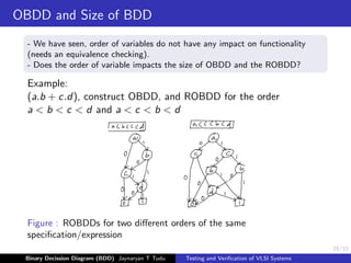
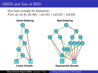
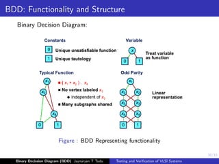
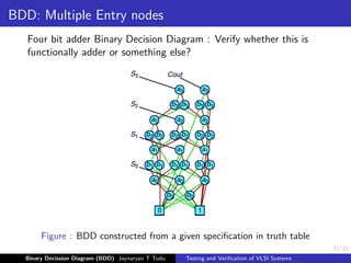
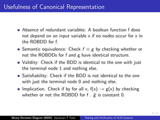
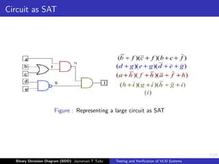
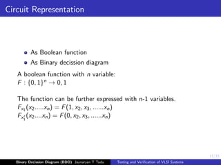
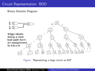
This document discusses binary decision diagrams (BDDs) and their use in formal verification of VLSI systems. It describes how BDDs can be constructed to represent Boolean functions and circuits. The ordering of variables in a BDD impacts its size, and ordered BDDs provide a canonical representation of functions. BDDs can be used for equivalence checking and other formal verification tasks by comparing the structure of BDDs representing different functions or circuits. Well-ordered BDDs provide an efficient way to perform tasks like validity checking, satisfiability checking, and implication checking on circuit representations.


![23/33
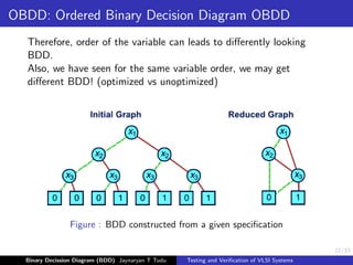
OBDD: Ordered Binary Decision Diagram OBDD
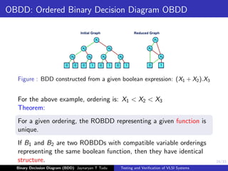
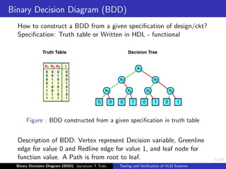
Figure : BDD constructed from a given boolean expression: (X1 + X2).X3
Ordered BDD:
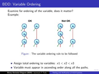
Let [x1, ..., xn] be an ordered list of variables without duplicates;
A BDD B has an ordering [x1, ..., xn] if
1. all variables of B occur in [x1, ..., xn]; and
2. if xj follows xi on a path in B then j > i
An ordered BDD (OBDD) is a BDD which has an ordering for some
list of variables.
The orderings of two OBBDs B and B’ are compatible if there are
no variables x, y such that: x is before y in the ordering for B, and y
is before x in the ordering for B’
Binary Decission Diagram (BDD) Jaynaryan T Tudu Testing and Verification of VLSI Systems](https://image.slidesharecdn.com/tnvlecture1-231030041149-d8bf3185/85/Vlsi-pdf-22-320.jpg)