This document provides an introduction to vision systems for robotics. It discusses various components of vision systems including image sensors like CCD and CMOS, frame grabbers, lighting techniques, image formation and geometry, sampling and quantization, and image acquisition. It provides examples of different types of vision systems and sensors as well as an overview of key concepts in digital image processing.
![Vision Optics
• Vision Systems
• Stand alone
• PC based
• Smart Camera
• Self contained [no pc req.]
• CCD image sensors
• CMOS image sensors
• Vision Sensors
• Integrated devices
• No programming required
• Between smart cams and vision systems
• Digital Cameras
• CCD image
• CMOS image
• Flash memory
• Memory stick
• SmartMedia cards
• Removable [microdrives,CD,DVD]
Hema –SR Lecture 8 3
Neural Network-Based
ZiCAMs from JAI Pulnix
Compact Vision System
from National Instruments
A Cognex In-Sight
Vision Sensor](https://image.slidesharecdn.com/visionbasics-210930045509/75/Vision-Basics-3-2048.jpg)
![Hema –SR Lecture 8 5
Frame Grabbers
• A frame grabber is a device to
acquire [grab] and convert
analog to digital images. Modern
FG have many additional
features like more storage,
multiple camera links etc.](https://image.slidesharecdn.com/visionbasics-210930045509/75/Vision-Basics-5-2048.jpg)
![13 Hema –SR Lecture 8
Image Geometry
• Image Formation has two divisions
• Geometry of image formation
• Physics of light [brightness of point]
• Image geometry determines where a world point is
projected on the image plane](https://image.slidesharecdn.com/visionbasics-210930045509/75/Vision-Basics-13-2048.jpg)
![14 Hema –SR Lecture 8
Image Geometry
• Object point is represented by x, y and z 3D co-
ordinates.
• Image plane is parallel to x and y axis [world] at a
distance f [focal length]
z
x`
y`
y (x,y,z)
(x`, y`)
Object Point
f r
r`
x
y
2
2
y
x
r
2
2
y
x
r
](https://image.slidesharecdn.com/visionbasics-210930045509/75/Vision-Basics-14-2048.jpg)
![15 Hema –SR Lecture 8
Image Sampling
• Continuous images are sampled to convert them to digital
form
• Each image sample is called a pixel [picture element]
• Sampling is the process of representing a continuous signal
by a set of samples taken at discrete intervals of time
[sampling interval]
Continuous Signal
Sampled Signal
Sampling Frequency
T
fs
1
](https://image.slidesharecdn.com/visionbasics-210930045509/75/Vision-Basics-15-2048.jpg)
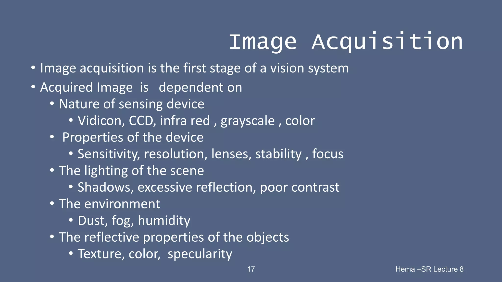
![19 Hema –SR Lecture 8
Image Acquisition
• Acquisition [capture] of 2D Images
• Monochrome or Color
• Analog Cameras
• Digital CCD Cameras
• Digital CMOS Cameras
• Video Cameras [Analog and Digital]](https://image.slidesharecdn.com/visionbasics-210930045509/75/Vision-Basics-19-2048.jpg)
![23 Hema –SR Lecture 8
Image Definitions
• Pixel – A sample of the image intensity quantized to an
integer value
• Image – A two dimensional array of pixels
• Pixel
• Row and column indices [ i, j] are integer values
• Pixels have intensity values
• 0 to 255 grayscale images
• RGB value [vector value] color images](https://image.slidesharecdn.com/visionbasics-210930045509/75/Vision-Basics-23-2048.jpg)
![24 Hema –SR Lecture 8
Pixel Array
Pixel [4,4] ↓i →j](https://image.slidesharecdn.com/visionbasics-210930045509/75/Vision-Basics-24-2048.jpg)
![26 Hema –SR Lecture 8
Image File Formats
• Images are stored in a computer in one of the following
formats, depending on the application of the images stored.
• Tagged Image Format [.tif]
• Portable Network Graphics [.png]
• Joint Photographic Experts Group [.jpeg, .jpg]
• Bitmap [.bmp]
• Graphics Interchange Format [.gif]
• Raster Images [.ras]
• Postscript [.ps]](https://image.slidesharecdn.com/visionbasics-210930045509/75/Vision-Basics-26-2048.jpg)