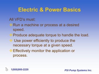
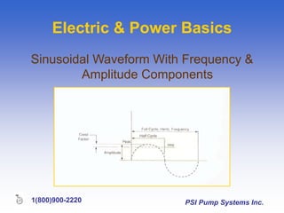
PSI Pump Systems Inc.
1(800)900-2220
PSI Pump Systems Inc.
1(800)900-2220
Variable Frequency Drives
Presented by
PSI Pump Systems Inc.
“Your Solutions Experts for
Pumps & Water Treatment”
PSI Pump Systems Inc.
1(800)900-2220
The Purpose
of
VFD’s
PSI Pump Systems Inc.
1(800)900-2220
The Purpose
1. Energy savings on most pump and fan applications.
2. Better process control and regulation.
3. Speeding up or slowing down a machine or process.
4. Inherent power-factor correction
5. Emergency bypass capability
6. Protection from overload currents
7. Safe Acceleration
PSI Pump Systems Inc.
1(800)900-2220
Electric & Power Basics
All VFD’s must:
Run a machine or process at a desired
speed.
Produce adequate torque to handle the load.
 Use power efficiently to produce the
necessary torque at a given speed.
Effectively monitor the application or
process.
PSI Pump Systems Inc.
1(800)900-2220
Electric & Power Basics
The typical waveform consists of the
frequency portion (time based) of the wave
and the amplitude portion (the magnitude).
This wave is actually in sine-wave form,
commonly referred to as the fundamental.
PSI Pump Systems Inc.
1(800)900-2220
Electric & Power Basics
Sinusoidal Waveform With Frequency &
Amplitude Components
PSI Pump Systems Inc.
1(800)900-2220
AC-Induction-Motor Theory
PSI Pump Systems Inc.
1(800)900-2220
AC Induction Motor Theory
AC Induction Motor – Squirrel Cage Design
PSI Pump Systems Inc.
1(800)900-2220
AC Induction Motor Theory
Three-phase
motor operation.
PSI Pump Systems Inc.
1(800)900-2220
AC Induction Motor Theory
How a motor shaft rotates
 Torque is produced as the induction
motor generates flux in its rotating
field.
 This flux must remain constant to
produce full-load torque.
PSI Pump Systems Inc.
1(800)900-2220
AC Induction Motor Theory
 As shaft torque load increases, the slip
increases and more flux lines cut the
rotor windings, which in turn increases
rotor current, which increases the rotor
magnetic field and consequently the
rotor torque.
PSI Pump Systems Inc.
1(800)900-2220
AC Induction Motor Theory
Typical speed
versus torque
curve for a NEMA
design B motor.
% Synchronous Speed
PSI Pump Systems Inc.
1(800)900-2220
AC Induction Motor Issues
Starting Induction Motors
 The starting current is very high, between 3 to 8
times the full load current. Depending on the size
of the motor, this can result in voltage sags in the
power system.
 The full torque is applied instantly at starting and
the mechanical shock can eventually damage the drive
system, particularly with materials handling
equipment, such as conveyors.
 In spite of the high starting current, for some
applications the starting torque may be relatively
low, only 1.0 to 2.5 times full load torque.
PSI Pump Systems Inc.
1(800)900-2220
AC Induction Motor Theory
The speed of the rotating electric field
within the induction motor.
Synchronous Speed = 120 x frequency
# of motor poles
PSI Pump Systems Inc.
1(800)900-2220
AC Induction Motor Theory
AC motor speed change can be accomplished
in three ways:
(1) Change the number of poles in the motor; this means
separate windings;
(2) Change the slip characteristics of the motor; this is
done with varying resistors, such as is done with a
wound-rotor motor or by varying the stator voltage; or
(3) Change the frequency of the power supplied to the
motor. This is the method of choice .
PSI Pump Systems Inc.
1(800)900-2220
Components of VFD’s
 Power electronics is that field of
electronics which covers the
conversion of electrical energy
from one form to another for high
power applications.
PSI Pump Systems Inc.
1(800)900-2220
Components of VFD’s
 Vacuum tubes
 Thyristors (SCR’s)
 provided the standard method for
rectifying AC. Also referred to as a
diode.
PSI Pump Systems Inc.
1(800)900-2220
Components of VFD’s
 Transistors provide fast switching capability
for a relatively low cost.
 The general types of transistors are:
» The bipolar transistor;
» The gate turn off transistor (GTO)
» The field-effect transistor (FET);
» The insulated gate-field-effect transistor (IGFET);
» The insulated gate-bipolar transistor (IGBT).
PSI Pump Systems Inc.
1(800)900-2220
VFD Basics
A VFD in a
block
diagram.
PSI Pump Systems Inc.
1(800)900-2220
Components of VFD’s
 All VFD’s need a power section that
converts AC power into DC power.
 This is called the converter bridge.
 Sometimes the front end of the VFD,
the converter is commonly a three-
phase, full-wave-diode bridge.
PSI Pump Systems Inc.
1(800)900-2220
Components of VFD’s
Rectifier is that special type of converter that
converts AC to DC.
PSI Pump Systems Inc.
1(800)900-2220
VFD Basics
DC Bus
 The DC bus is the true link between
the converter and inverter sections of
the drive. Any ripple must be
smoothed out before any transistor
switches “on”. If not, this distortion will
show up in the output to the motor. The
DC bus voltage and current can be
viewed through the bus terminals.
PSI Pump Systems Inc.
1(800)900-2220
VFD Basics
Simplified Circuit showing DC bus components:
The DC link is an important section of the drive as it provides much of the monitoring
and protection for the drive & motor circuit. It contains the base-drive fusing and pre-
charge capacitor network, which assures steady voltage DC voltage levels prior to the
inverter bridge and allows a path for over-voltage dissipation.
PSI Pump Systems Inc.
1(800)900-2220
VFD Basics
Input Waveforms
 The voltage that is not stepped down is
rectified through the diodes, and a DC bus
voltage should be present.
 The DC + and DC – terminals will typically
read approximately 325 volts DC on a 230
volts AC supplied drive and 650 volts DC on a
460 volts AC supplied drive.
 This waveform, when viewed, is straight
DC, possibly with some rippling effect from
the AC input.
PSI Pump Systems Inc.
1(800)900-2220
VFD Basics
Power-Module
 The inverter section is made up
primarily of modules that are each
made up of a transistor and diode in
combination with each other which
inverts the DC energy back to AC.
PSI Pump Systems Inc.
1(800)900-2220
VFD Basics
Simplified
Inverter
Section of a
VFD
PSI Pump Systems Inc.
1(800)900-2220
VFD Basics
 The DC waveform looks more like an
AC waveform but the voltage
waveform is much different.
 The power semi-conductors in the
inverter section act as switches,
switches of the DC bus, and
therefore, are pulsing the motor with
some voltage.
PSI Pump Systems Inc.
1(800)900-2220
VFD Basics
A typical square wave takes its shape on
the square-wave look due to this switching
function ( which explains the sharp rise to
peak) rather than a rotational, changing
state of amplitude.
This frequency and amplitude pattern is
sometimes called the carrier frequency of
a PWM drive.
PSI Pump Systems Inc.
1(800)900-2220
VFD Basics
Pulse-width-modulated voltage and current
waveforms.
PSI Pump Systems Inc.
1(800)900-2220
VFD Basics
 The VFD changes the DC energy into
three channels of AC energy that an
AC induction motor can use to function
properly.
 Inverters are classified as voltage-
source, current-source of variable-
voltage types. This has to do with the
form of DC that the inverter receives from
the DC bus.
PSI Pump Systems Inc.
1(800)900-2220
VFD Basics
Types of VFD’s
 Solid-state AC VFD’s can be named
for their use, by their DC bus/inverter
voltage or current source, by their
waveform (PWM or PAM), by the type of
power device used in their inverter
section, or by their performance
characteristics.
PSI Pump Systems Inc.
1(800)900-2220
VFD Basics
The main objective of the VFD is to vary
the speed of the motor while providing the
closest approximation to a sine wave for
current (while pulsing DC voltage to the
motor).
PSI Pump Systems Inc.
1(800)900-2220
VFD Basics
Volts-per-
Hertz
Control
The area within
each pulse is the
power delivered
to the motor in
volt-
microseconds.
PSI Pump Systems Inc.
1(800)900-2220
VFD Basics
How VFD’s Operate
The PWMs drive ability to maintain the AC
levels through all types of load conditions
at given speeds is the factor which
separates one drive manufacturer from the
other.
PSI Pump Systems Inc.
1(800)900-2220
VFD Basics
Functions & Features
 Set-up Parameters
 The Control Method
 Acceleration or Accel-Ramp Rate
 Automatic Restart
 Stopping Method
 Automatic Signals
PSI Pump Systems Inc.
1(800)900-2220
VFD Basics
Functions & Features
 Jump, Skip or Critical Frequencies
 Fault Logs and On-Board
Diagnostics
 Power Loss Ride Through
 Slip Compensation
 Catch a Rotating Motor, Speed
Search or Pick-Up a Spinning Load
PSI Pump Systems Inc.
1(800)900-2220
VFD Basics
Conclusion
 Significant energy savings
 Easy setup & programming
 Retrofits
 Space
 Better design
 Competitive edge

Variable Frequency Drive.ppt

  • 1.
    PSI Pump SystemsInc. 1(800)900-2220
  • 2.
    PSI Pump SystemsInc. 1(800)900-2220 Variable Frequency Drives Presented by PSI Pump Systems Inc. “Your Solutions Experts for Pumps & Water Treatment”
  • 3.
    PSI Pump SystemsInc. 1(800)900-2220 The Purpose of VFD’s
  • 4.
    PSI Pump SystemsInc. 1(800)900-2220 The Purpose 1. Energy savings on most pump and fan applications. 2. Better process control and regulation. 3. Speeding up or slowing down a machine or process. 4. Inherent power-factor correction 5. Emergency bypass capability 6. Protection from overload currents 7. Safe Acceleration
  • 5.
    PSI Pump SystemsInc. 1(800)900-2220 Electric & Power Basics All VFD’s must: Run a machine or process at a desired speed. Produce adequate torque to handle the load.  Use power efficiently to produce the necessary torque at a given speed. Effectively monitor the application or process.
  • 6.
    PSI Pump SystemsInc. 1(800)900-2220 Electric & Power Basics The typical waveform consists of the frequency portion (time based) of the wave and the amplitude portion (the magnitude). This wave is actually in sine-wave form, commonly referred to as the fundamental.
  • 7.
    PSI Pump SystemsInc. 1(800)900-2220 Electric & Power Basics Sinusoidal Waveform With Frequency & Amplitude Components
  • 8.
    PSI Pump SystemsInc. 1(800)900-2220 AC-Induction-Motor Theory
  • 9.
    PSI Pump SystemsInc. 1(800)900-2220 AC Induction Motor Theory AC Induction Motor – Squirrel Cage Design
  • 10.
    PSI Pump SystemsInc. 1(800)900-2220 AC Induction Motor Theory Three-phase motor operation.
  • 11.
    PSI Pump SystemsInc. 1(800)900-2220 AC Induction Motor Theory How a motor shaft rotates  Torque is produced as the induction motor generates flux in its rotating field.  This flux must remain constant to produce full-load torque.
  • 12.
    PSI Pump SystemsInc. 1(800)900-2220 AC Induction Motor Theory  As shaft torque load increases, the slip increases and more flux lines cut the rotor windings, which in turn increases rotor current, which increases the rotor magnetic field and consequently the rotor torque.
  • 13.
    PSI Pump SystemsInc. 1(800)900-2220 AC Induction Motor Theory Typical speed versus torque curve for a NEMA design B motor. % Synchronous Speed
  • 14.
    PSI Pump SystemsInc. 1(800)900-2220 AC Induction Motor Issues Starting Induction Motors  The starting current is very high, between 3 to 8 times the full load current. Depending on the size of the motor, this can result in voltage sags in the power system.  The full torque is applied instantly at starting and the mechanical shock can eventually damage the drive system, particularly with materials handling equipment, such as conveyors.  In spite of the high starting current, for some applications the starting torque may be relatively low, only 1.0 to 2.5 times full load torque.
  • 15.
    PSI Pump SystemsInc. 1(800)900-2220 AC Induction Motor Theory The speed of the rotating electric field within the induction motor. Synchronous Speed = 120 x frequency # of motor poles
  • 16.
    PSI Pump SystemsInc. 1(800)900-2220 AC Induction Motor Theory AC motor speed change can be accomplished in three ways: (1) Change the number of poles in the motor; this means separate windings; (2) Change the slip characteristics of the motor; this is done with varying resistors, such as is done with a wound-rotor motor or by varying the stator voltage; or (3) Change the frequency of the power supplied to the motor. This is the method of choice .
  • 17.
    PSI Pump SystemsInc. 1(800)900-2220 Components of VFD’s  Power electronics is that field of electronics which covers the conversion of electrical energy from one form to another for high power applications.
  • 18.
    PSI Pump SystemsInc. 1(800)900-2220 Components of VFD’s  Vacuum tubes  Thyristors (SCR’s)  provided the standard method for rectifying AC. Also referred to as a diode.
  • 19.
    PSI Pump SystemsInc. 1(800)900-2220 Components of VFD’s  Transistors provide fast switching capability for a relatively low cost.  The general types of transistors are: » The bipolar transistor; » The gate turn off transistor (GTO) » The field-effect transistor (FET); » The insulated gate-field-effect transistor (IGFET); » The insulated gate-bipolar transistor (IGBT).
  • 20.
    PSI Pump SystemsInc. 1(800)900-2220 VFD Basics A VFD in a block diagram.
  • 21.
    PSI Pump SystemsInc. 1(800)900-2220 Components of VFD’s  All VFD’s need a power section that converts AC power into DC power.  This is called the converter bridge.  Sometimes the front end of the VFD, the converter is commonly a three- phase, full-wave-diode bridge.
  • 22.
    PSI Pump SystemsInc. 1(800)900-2220 Components of VFD’s Rectifier is that special type of converter that converts AC to DC.
  • 23.
    PSI Pump SystemsInc. 1(800)900-2220 VFD Basics DC Bus  The DC bus is the true link between the converter and inverter sections of the drive. Any ripple must be smoothed out before any transistor switches “on”. If not, this distortion will show up in the output to the motor. The DC bus voltage and current can be viewed through the bus terminals.
  • 24.
    PSI Pump SystemsInc. 1(800)900-2220 VFD Basics Simplified Circuit showing DC bus components: The DC link is an important section of the drive as it provides much of the monitoring and protection for the drive & motor circuit. It contains the base-drive fusing and pre- charge capacitor network, which assures steady voltage DC voltage levels prior to the inverter bridge and allows a path for over-voltage dissipation.
  • 25.
    PSI Pump SystemsInc. 1(800)900-2220 VFD Basics Input Waveforms  The voltage that is not stepped down is rectified through the diodes, and a DC bus voltage should be present.  The DC + and DC – terminals will typically read approximately 325 volts DC on a 230 volts AC supplied drive and 650 volts DC on a 460 volts AC supplied drive.  This waveform, when viewed, is straight DC, possibly with some rippling effect from the AC input.
  • 26.
    PSI Pump SystemsInc. 1(800)900-2220 VFD Basics Power-Module  The inverter section is made up primarily of modules that are each made up of a transistor and diode in combination with each other which inverts the DC energy back to AC.
  • 27.
    PSI Pump SystemsInc. 1(800)900-2220 VFD Basics Simplified Inverter Section of a VFD
  • 28.
    PSI Pump SystemsInc. 1(800)900-2220 VFD Basics  The DC waveform looks more like an AC waveform but the voltage waveform is much different.  The power semi-conductors in the inverter section act as switches, switches of the DC bus, and therefore, are pulsing the motor with some voltage.
  • 29.
    PSI Pump SystemsInc. 1(800)900-2220 VFD Basics A typical square wave takes its shape on the square-wave look due to this switching function ( which explains the sharp rise to peak) rather than a rotational, changing state of amplitude. This frequency and amplitude pattern is sometimes called the carrier frequency of a PWM drive.
  • 30.
    PSI Pump SystemsInc. 1(800)900-2220 VFD Basics Pulse-width-modulated voltage and current waveforms.
  • 31.
    PSI Pump SystemsInc. 1(800)900-2220 VFD Basics  The VFD changes the DC energy into three channels of AC energy that an AC induction motor can use to function properly.  Inverters are classified as voltage- source, current-source of variable- voltage types. This has to do with the form of DC that the inverter receives from the DC bus.
  • 32.
    PSI Pump SystemsInc. 1(800)900-2220 VFD Basics Types of VFD’s  Solid-state AC VFD’s can be named for their use, by their DC bus/inverter voltage or current source, by their waveform (PWM or PAM), by the type of power device used in their inverter section, or by their performance characteristics.
  • 33.
    PSI Pump SystemsInc. 1(800)900-2220 VFD Basics The main objective of the VFD is to vary the speed of the motor while providing the closest approximation to a sine wave for current (while pulsing DC voltage to the motor).
  • 34.
    PSI Pump SystemsInc. 1(800)900-2220 VFD Basics Volts-per- Hertz Control The area within each pulse is the power delivered to the motor in volt- microseconds.
  • 35.
    PSI Pump SystemsInc. 1(800)900-2220 VFD Basics How VFD’s Operate The PWMs drive ability to maintain the AC levels through all types of load conditions at given speeds is the factor which separates one drive manufacturer from the other.
  • 36.
    PSI Pump SystemsInc. 1(800)900-2220 VFD Basics Functions & Features  Set-up Parameters  The Control Method  Acceleration or Accel-Ramp Rate  Automatic Restart  Stopping Method  Automatic Signals
  • 37.
    PSI Pump SystemsInc. 1(800)900-2220 VFD Basics Functions & Features  Jump, Skip or Critical Frequencies  Fault Logs and On-Board Diagnostics  Power Loss Ride Through  Slip Compensation  Catch a Rotating Motor, Speed Search or Pick-Up a Spinning Load
  • 38.
    PSI Pump SystemsInc. 1(800)900-2220 VFD Basics Conclusion  Significant energy savings  Easy setup & programming  Retrofits  Space  Better design  Competitive edge