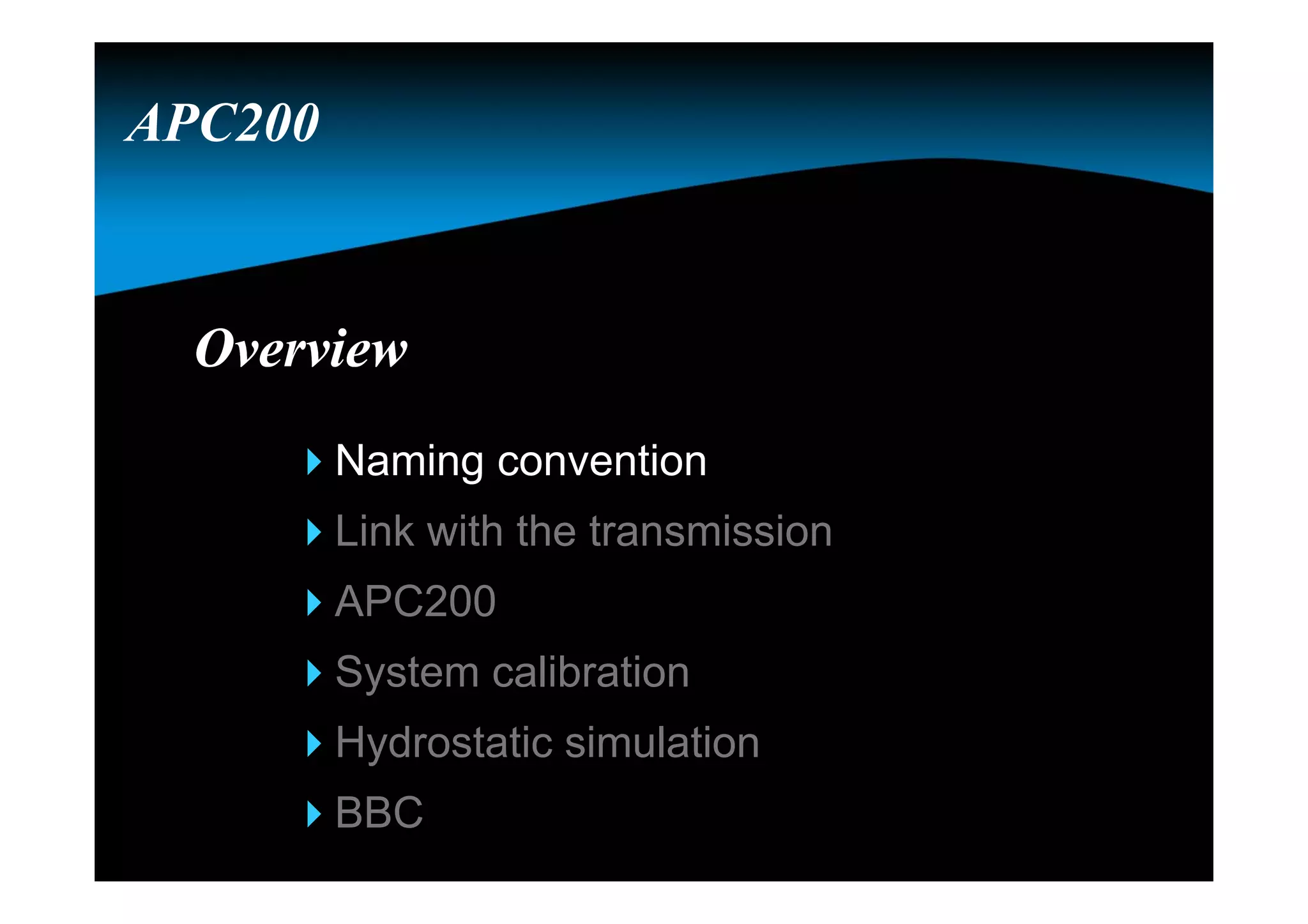
The document provides an overview of the APC200 controller, which is used to control Spicer Off Highway Products ECM powershift transmissions. It discusses the naming convention for CAN2B controllers, an overview of the APC200 controller including communication, parameter settings, and functions. It also describes the display, diagnostics, and testing capabilities of the APC200 controller.
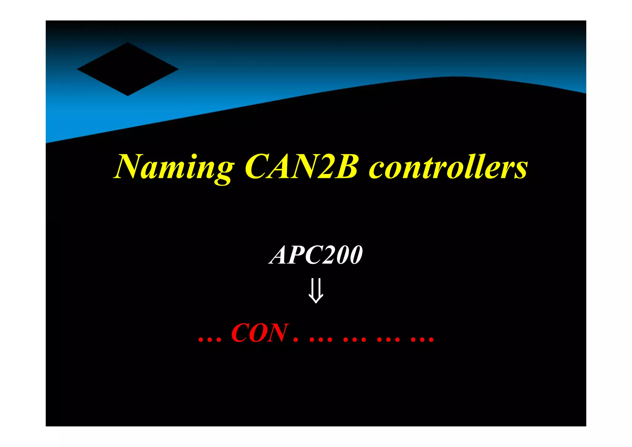
NamingNaming
… CON .… … … …
E, T, P, I or A
A, B, C, … etc.
120, 210, 211, 212, 213,
214, 215 or 216
Hardware reference
Functionality
Technology
7.
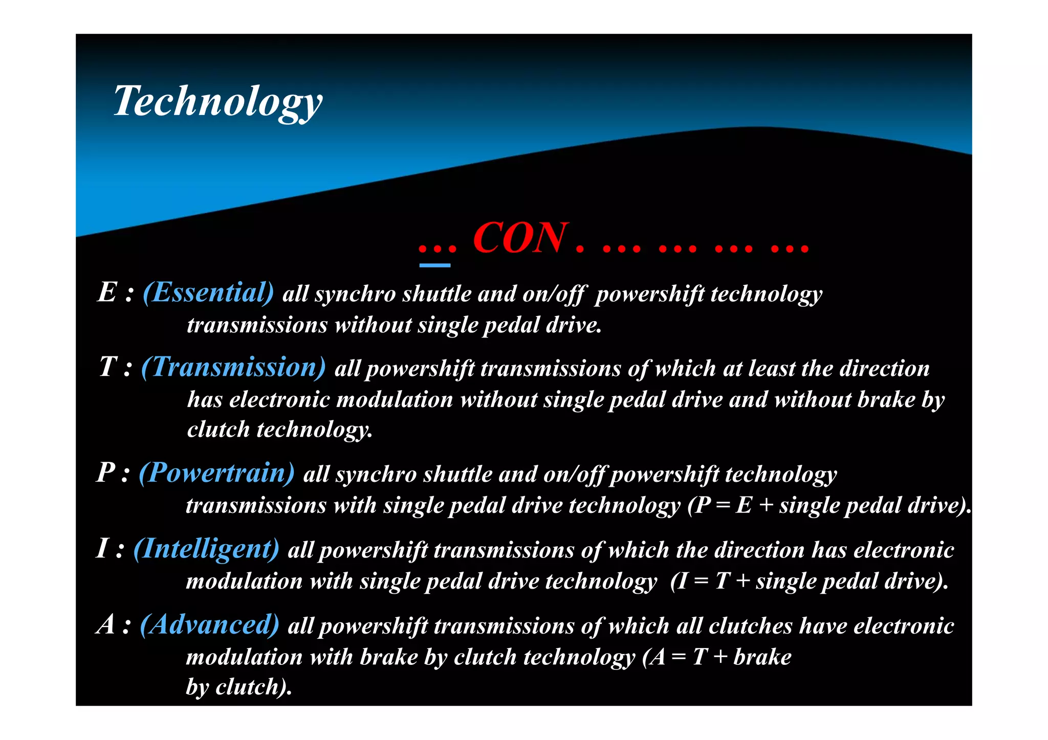
… CON .… … … …
E : (Essential) all synchro shuttle and on/off powershift technology
transmissions without single pedal drive.
T : (Transmission) all powershift transmissions of which at least the direction
has electronic modulation without single pedal drive and without brake by
clutch technology.
P : (Powertrain) all synchro shuttle and on/off powershift technology
transmissions with single pedal drive technology (P = E + single pedal drive).
I : (Intelligent) all powershift transmissions of which the direction has electronic
modulation with single pedal drive technology (I = T + single pedal drive).
A : (Advanced) all powershift transmissions of which all clutches have electronic
modulation with brake by clutch technology (A = T + brake
by clutch).
TechnologyTechnology
8.
… CON .… … … …
An alphabetic letter is used to reflect the functionality of the
firmware, made for a specific hardware in combination of the valve
and the transmission.
FunctionalityFunctionality
For the TCON :
Note : the functionality level is a level within the technology group.
A : all T16000 without ECI
B : all PS08 without ECI
C : all PS09 with ECI -PC
D : all T16000 with ECI-PC
E : all PS09 without ECI
F : all TE with VFS/booster valve (overlap & ECI-SC)
. . . Etc.
9.
Hardware referenceHardware reference
…CON . … … … …
210 : (APC201-12) 12 Volt / 4 PWM’s closed loop / No H-bridge / Analog inputs 2 & 4 V
211 : (APC201-24) 24 Volt / 4 PWM’s closed loop / No H-bridge / Analog inputs 2 & 4 V
212 : (APC202-12) 12 Volt / 4 PWM’s closed loop / H-bridge / Analog inputs 2 & 4 V
213 : (APC202-24) 24 Volt / 4 PWM’s closed loop / H-bridge / Analog inputs 2 & 4 V
214 : (APC200A) 12 Volt / 5 PWM’s closed loop / No H-bridge / Analog inputs 1 & 5 V
215 : (New -12) 12 Volt / 4 PWM’s closed loop / No H-bridge / Analog inputs 1 & 5 V
216 : (New -24) 24 Volt / 4 PWM’s closed loop / No H-bridge / Analog inputs 1 & 5 V
Note : the 215 & 216 R8 is needed for the TE15, TE13, TE17 andTE32 full flow
valve.
10.
ExampleExample
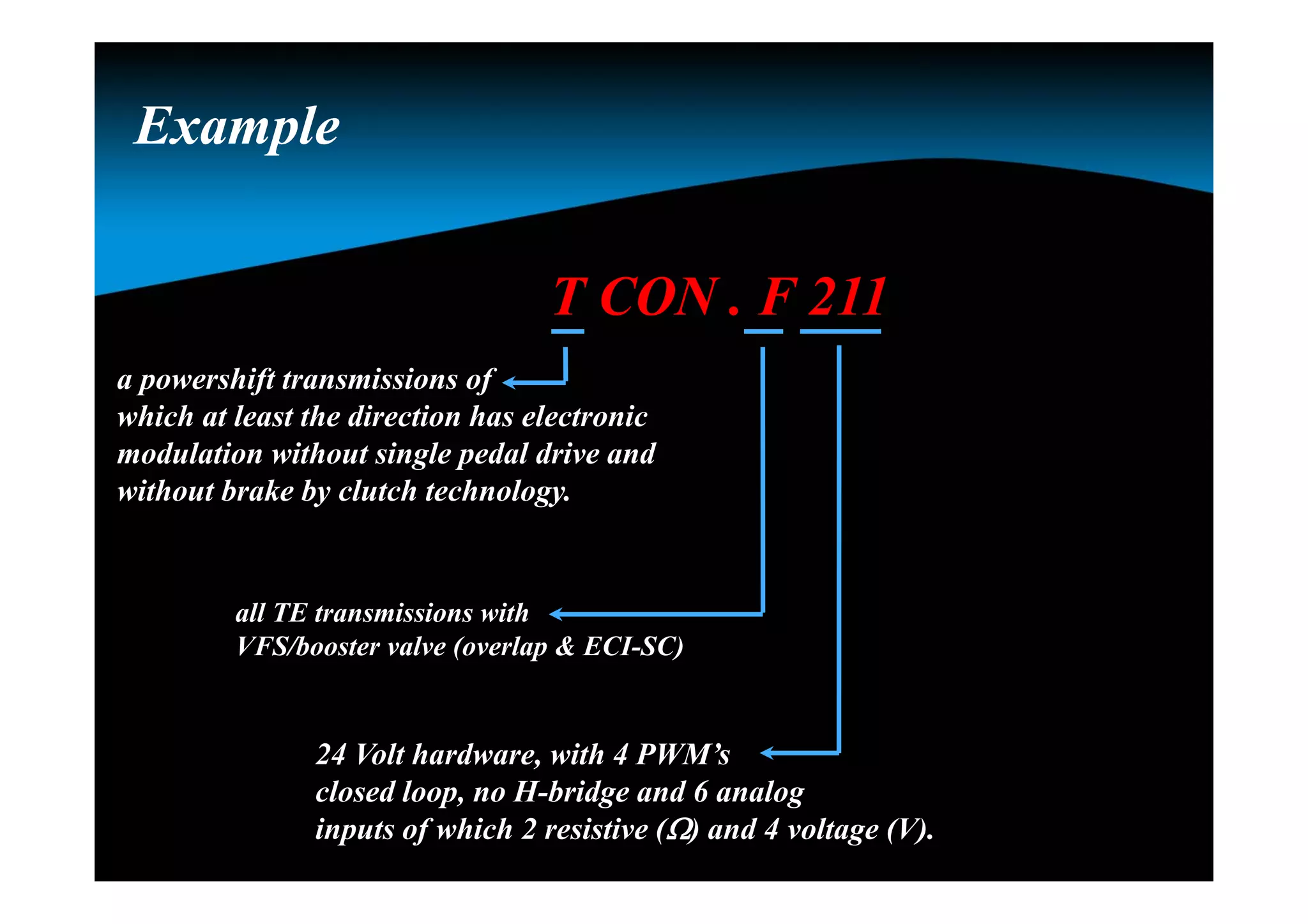
T CON .F 211
a powershift transmissions of
which at least the direction has electronic
modulation without single pedal drive and
without brake by clutch technology.
all TE transmissions with
VFS/booster valve (overlap & ECI-SC)
24 Volt hardware, with 4 PWM’s
closed loop, no H-bridge and 6 analog
inputs of which 2 resistive () and 4 voltage (V).
11.
ConclusionConclusion
ACON . A214
The 1st and 2nd part reflects
the firmware of the controller
The 3rd part reflects the
hardware of the controller
Additional signalsAdditional signals
Speedsensors
Engine speed
Turbine speed
Drum speed
Output speed
Pressure feedback sensor
Sump temperature sensor
Converter out temperature switch
TE 10
APC200
14.
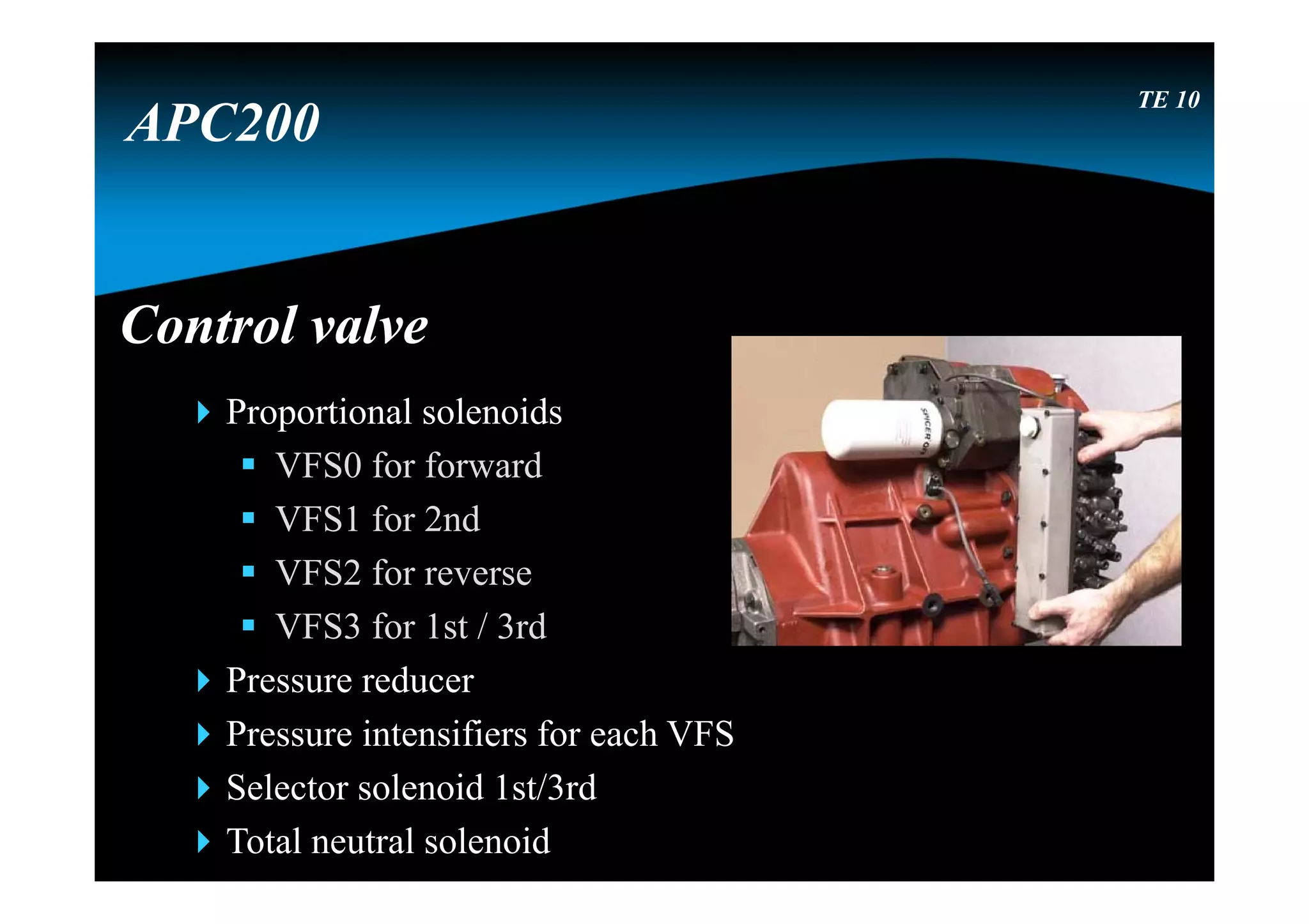
Control valveControl valve
Proportionalsolenoids
VFS0 for forward
VFS1 for 2nd
VFS2 for reverse
VFS3 for 1st / 3rd
Pressure reducer
Pressure intensifiers for each VFS
Selector solenoid 1st/3rd
Total neutral solenoid
TE 10
APC200
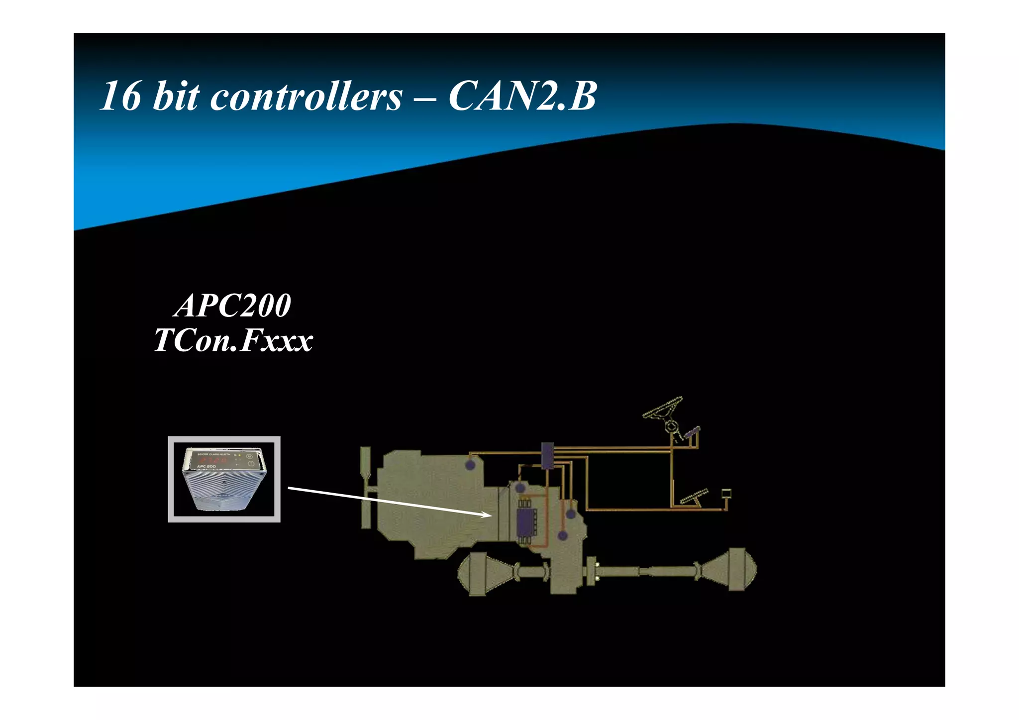
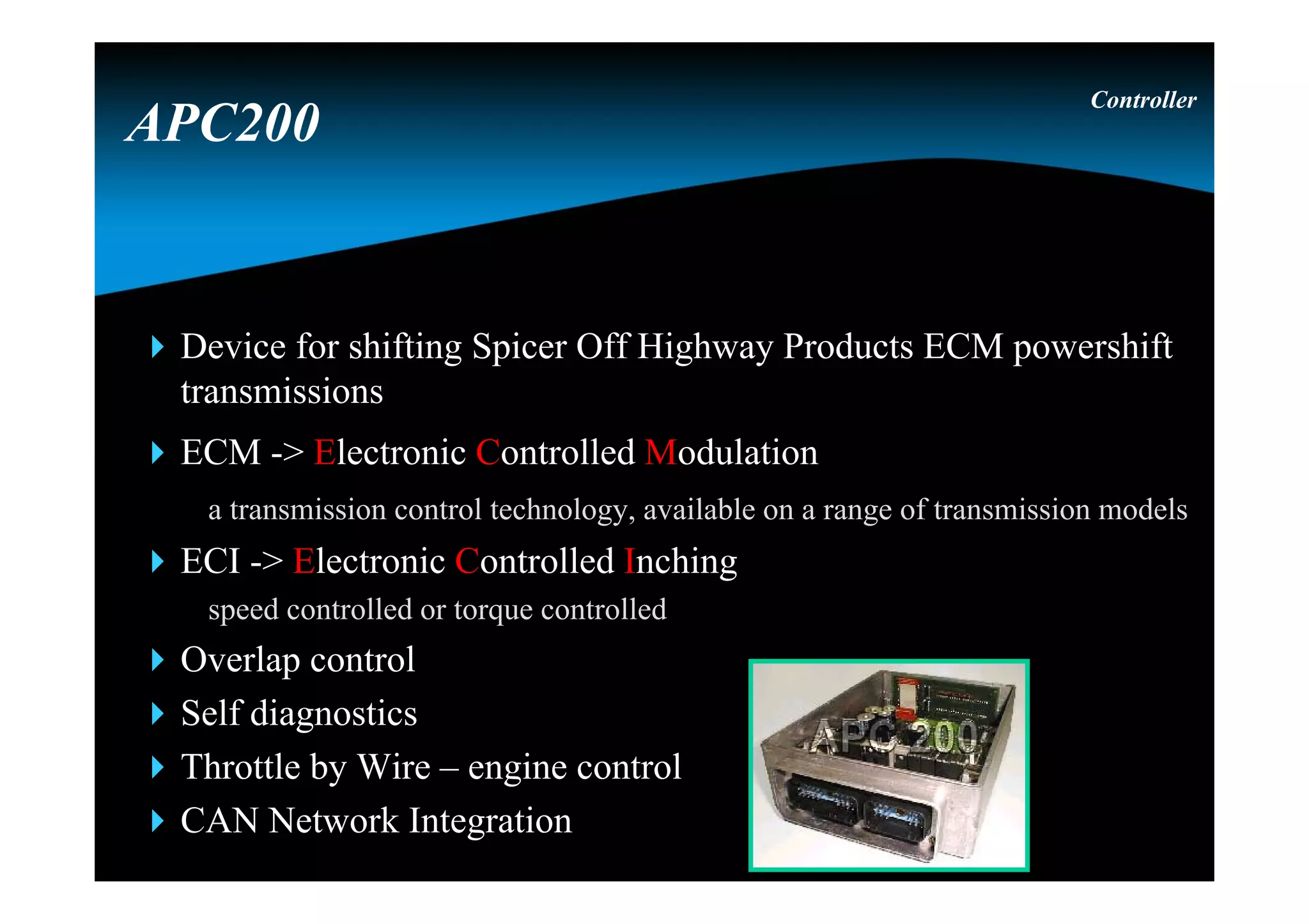
Device for shiftingSpicer Off Highway Products ECM powershift
transmissions
ECM -> Electronic Controlled Modulation
a transmission control technology, available on a range of transmission models
ECI -> Electronic Controlled Inching
speed controlled or torque controlled
Overlap control
Self diagnostics
Throttle by Wire – engine control
CAN Network Integration
Controller
APC200
18.
PSU = PowerSupply UnitPSU = Power Supply Unit
Version : 12V or 24V
Two power lines
PPWR : permanent power
Connected directly to the battery
SPWR : switched power
Connected via key contact to the battery
Controller
APC200
19.
Bootstrap and resetcircuitBootstrap and reset circuit
Bootstrap:
Special mode, controller wants to receive serial data, to
program the firmware into the program memory
While in bootstrap all output functions are hold off
Start : during power up both buttons pressed
Reset circuit : watchdog & supply supervisor will reset CPU if
either the power supply is outside 10% tolerance window or CPU
has “forgotten” to re-trigger the watchdog trigger²
Controller
APC200
20.
FunctionsFunctions
Manual / automaticshifting
Electronic modulation
Overlap control
Electronic inching
Start 1st / 2nd
Limit vehicle speed
Reduce vehicle speed
(by use of an input)
Limit engine speed
Controller
APC200
Direction change protection
(speed and engine RPM)
Declutch (inching / none inching)
Engine control
Seat orientation
Hydro lever function in neutral
21.
CommunicationCommunication
CAN 2.0 B
Communicate with different controllers and PC
RS 232
To flash a new firmware (main program)
To download the parameter settings (APT-file)
To edit specific parameters (GDE-file)
Controller
APC200
22.
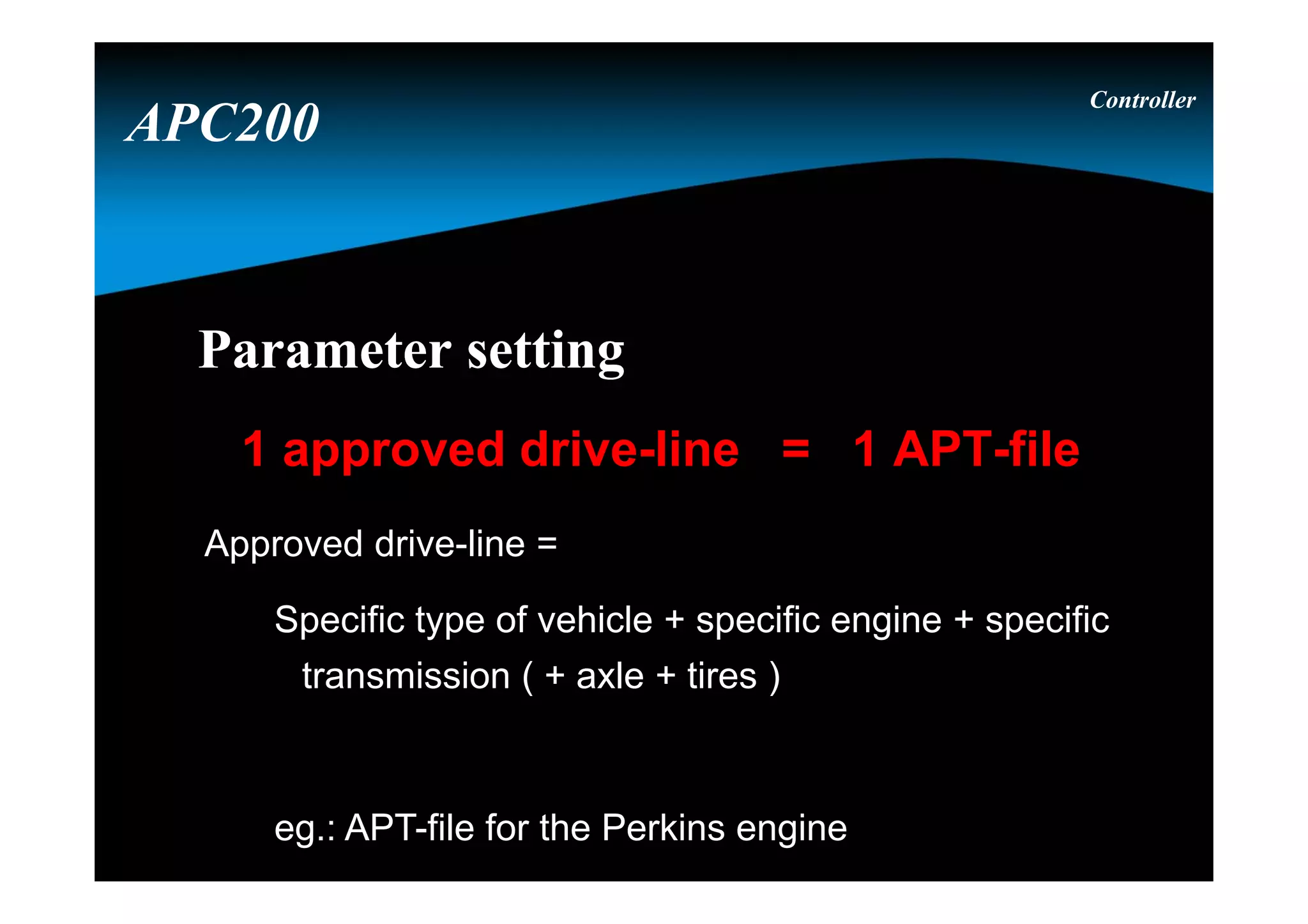
Parameter settingParameter setting
1approved drive-line = 1 APT-file
Approved drive-line =
Specific type of vehicle + specific engine + specific
transmission ( + axle + tires )
eg.: APT-file for the Perkins engine
Controller
APC200
GDE user levelsGDEuser levels
Controller
Maintenance (only for DANA engineering)
Service (only for DANA service)
OEM engineering
OEM service
APC200
26.
Parameters can havedifferent access levels
depending on the GDE user levels
Parameters can have different access levels
depending on the GDE user levels
Controller
Write access
Safe write access
Read access
Not visible
APC200
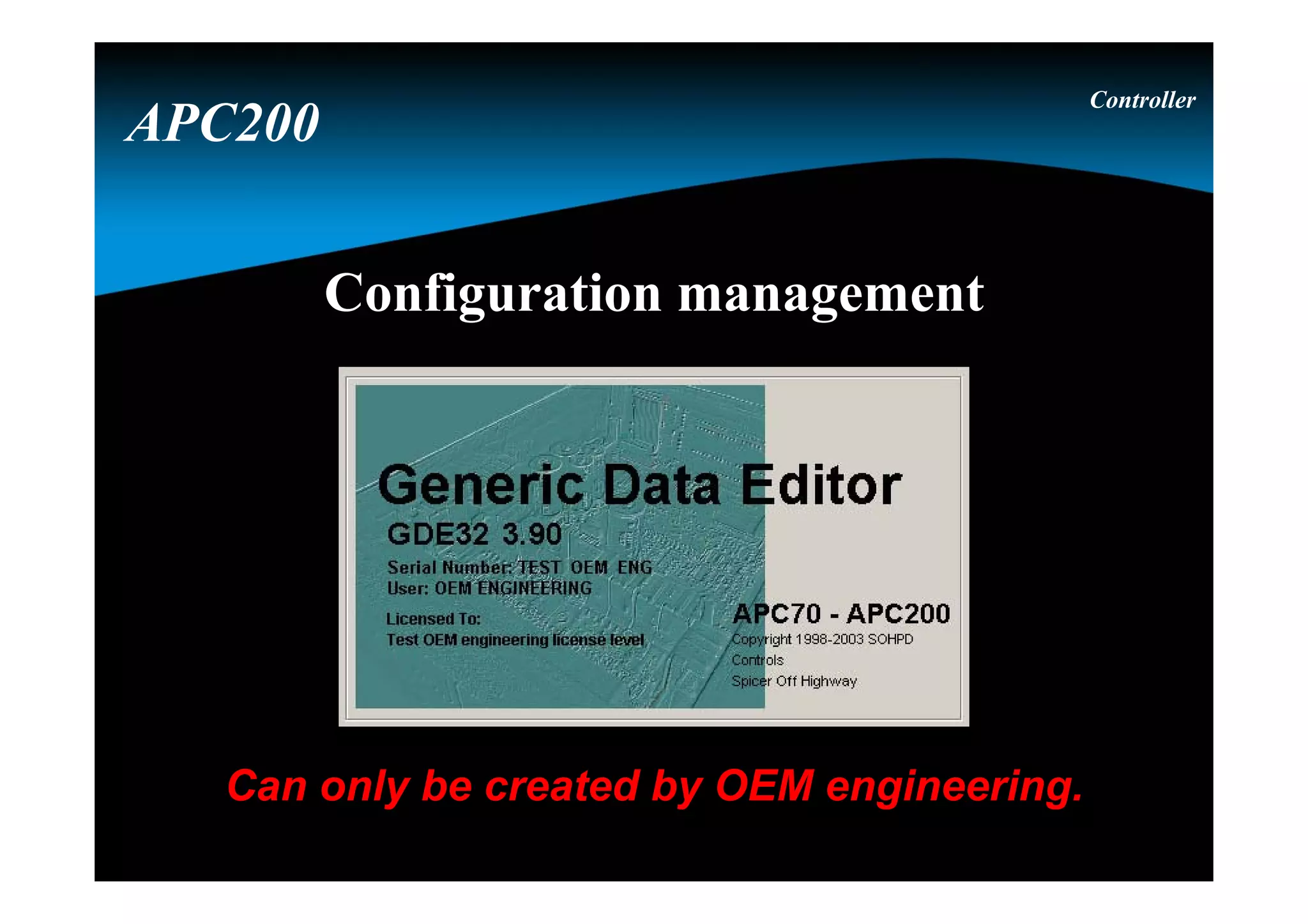
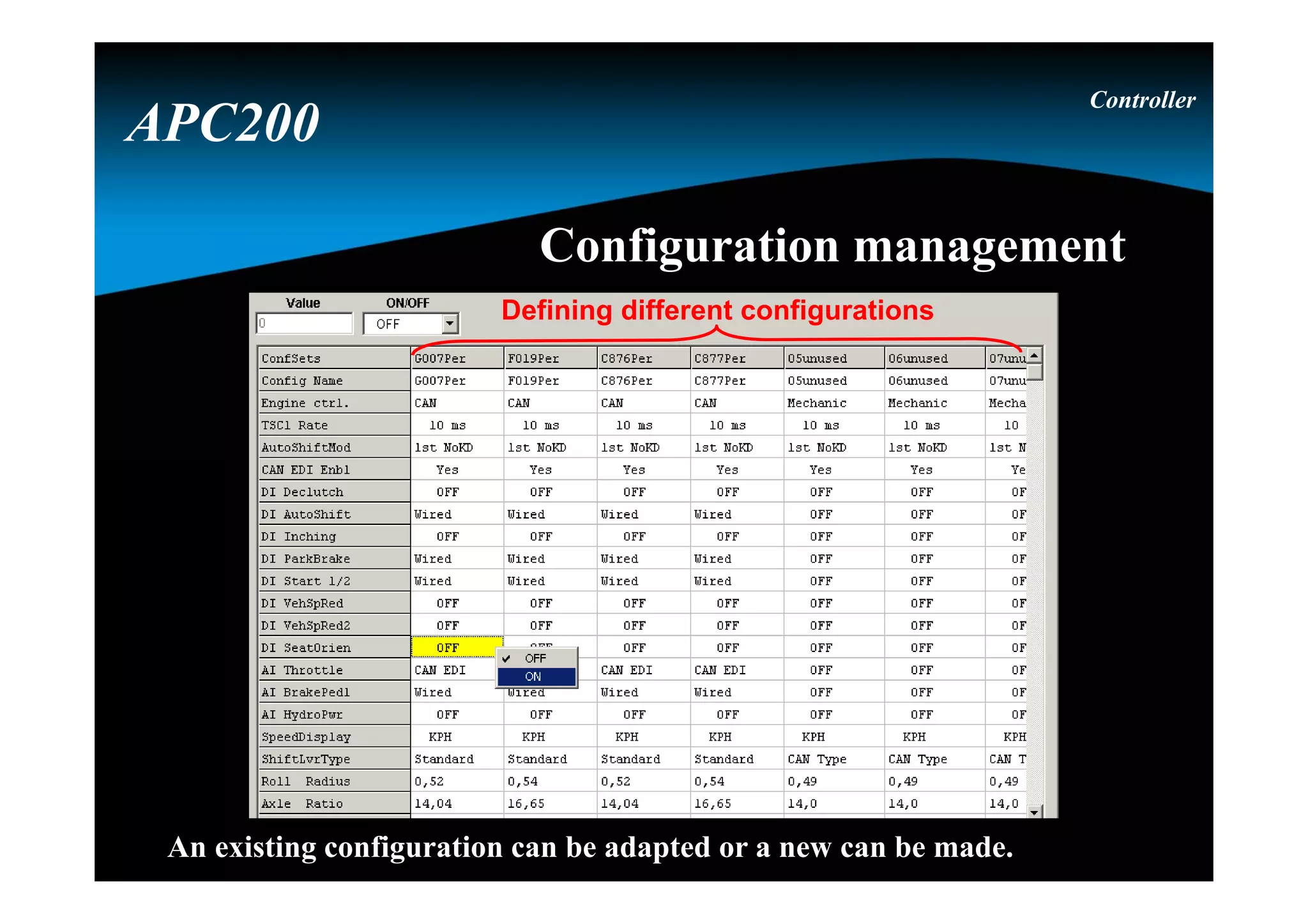
Different axles, tiresizes and functions are selected via
the configuration management.
The configuration management is the responsability of
the OEM engineering.
Controller
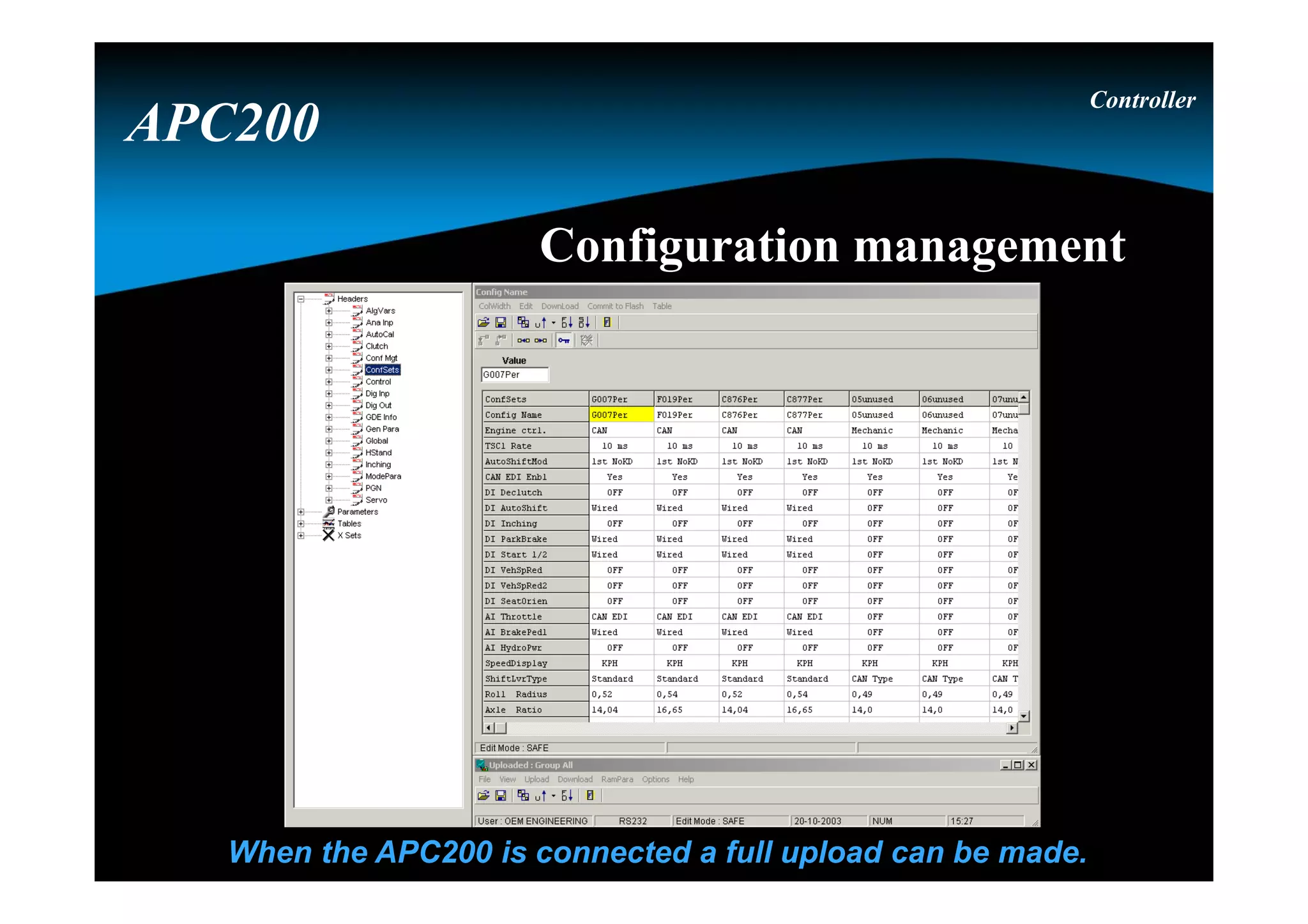
Configuration management
APC200
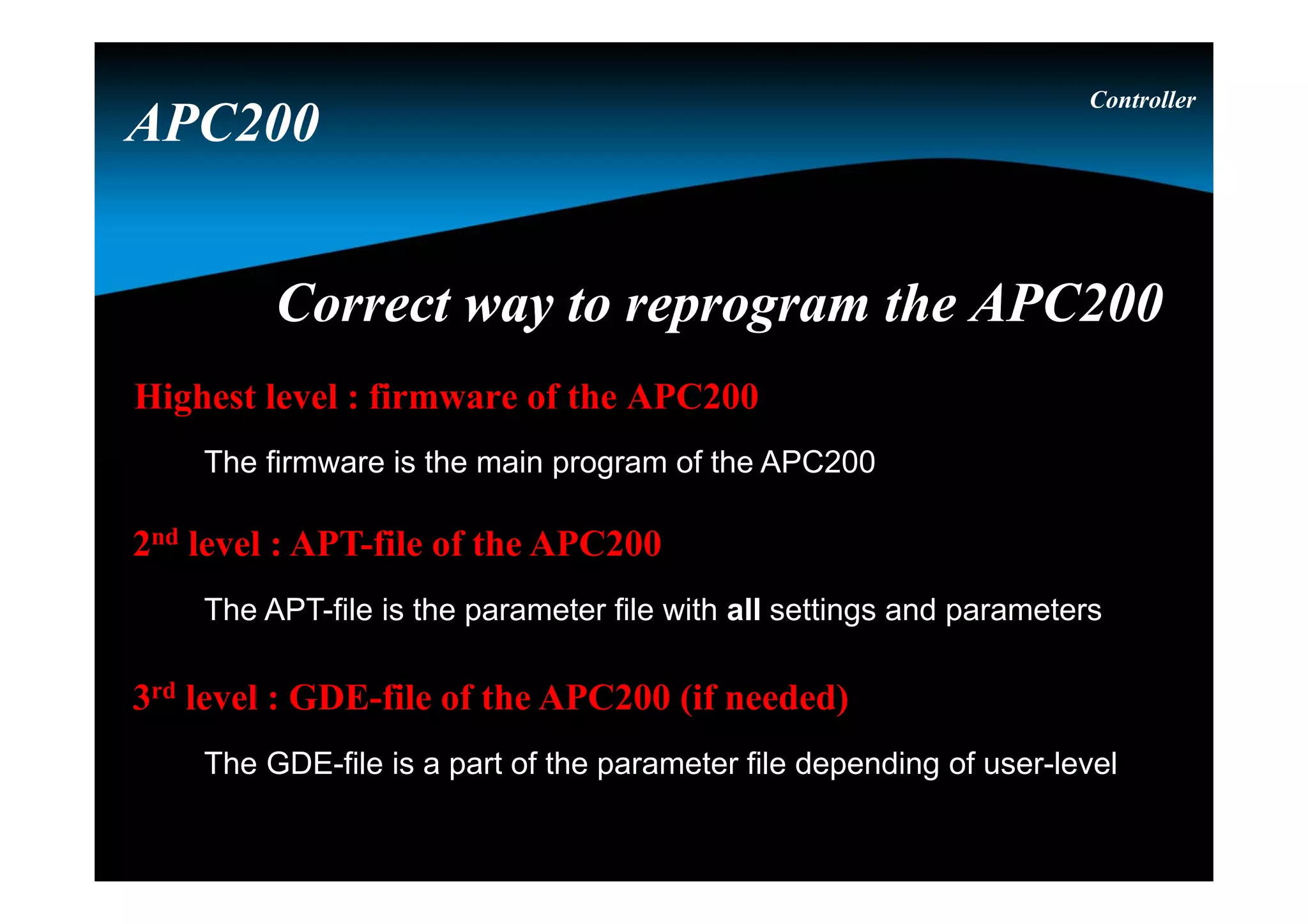
Correct way toreprogram the APC200Correct way to reprogram the APC200
Highest level : firmware of the APC200
The firmware is the main program of the APC200
2nd level : APT-file of the APC200
The APT-file is the parameter file with all settings and parameters
3rd level : GDE-file of the APC200 (if needed)
The GDE-file is a part of the parameter file depending of user-level
Controller
APC200
32.
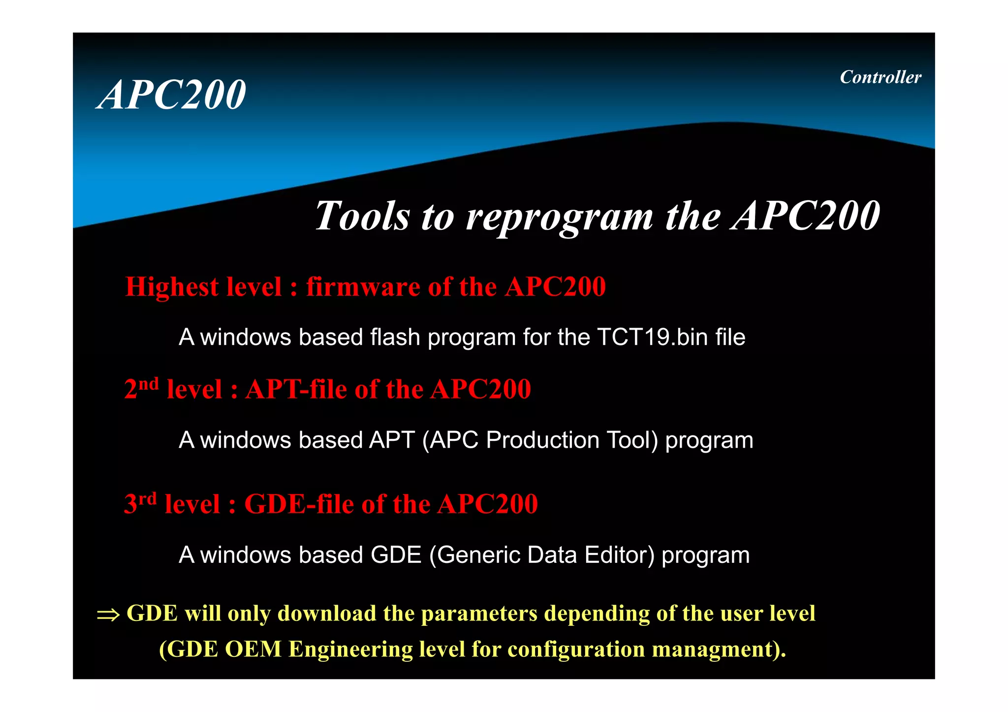
Tools to reprogramthe APC200Tools to reprogram the APC200
Highest level : firmware of the APC200
A windows based flash program for the TCT19.bin file
2nd level : APT-file of the APC200
A windows based APT (APC Production Tool) program
3rd level : GDE-file of the APC200
A windows based GDE (Generic Data Editor) program
GDE will only download the parameters depending of the user level
(GDE OEM Engineering level for configuration managment).
Controller
APC200
33.
APT to downloadall parameters / dataAPT to download all parameters / data
Configuration selection
Controller
APC200
DisplayDisplay 4 red7-segment LED digits
3 status LED lamps
• D -> yellow, Diagnostic modes
• E -> yellow, Error
• F -> red, Failure or APC 200 in
reset conditions
2 push buttons
• M -> which information group
• S -> item within group
Controller
APC200
36.
S S S
MM
M
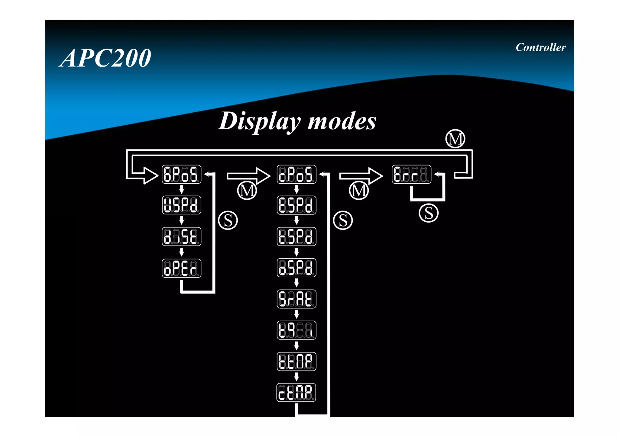
Display modesDisplay modes
Controller
APC200
37.
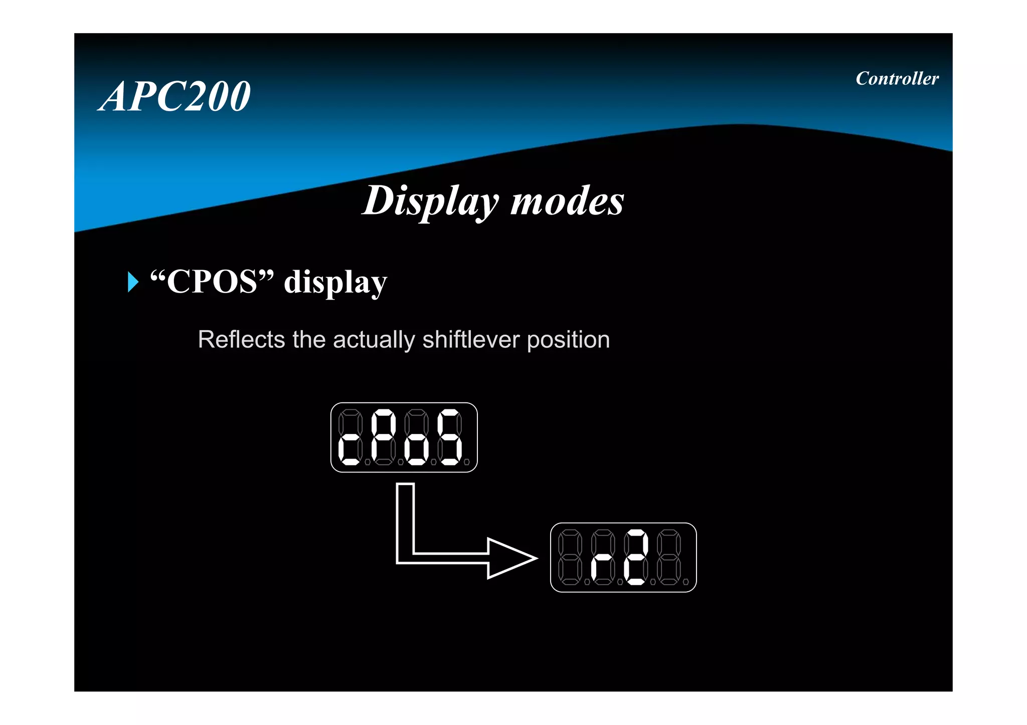
“GPOS” display
Reflects theactually engaged transmission direction and range
Controller
APC200
Display modesDisplay modes
38.
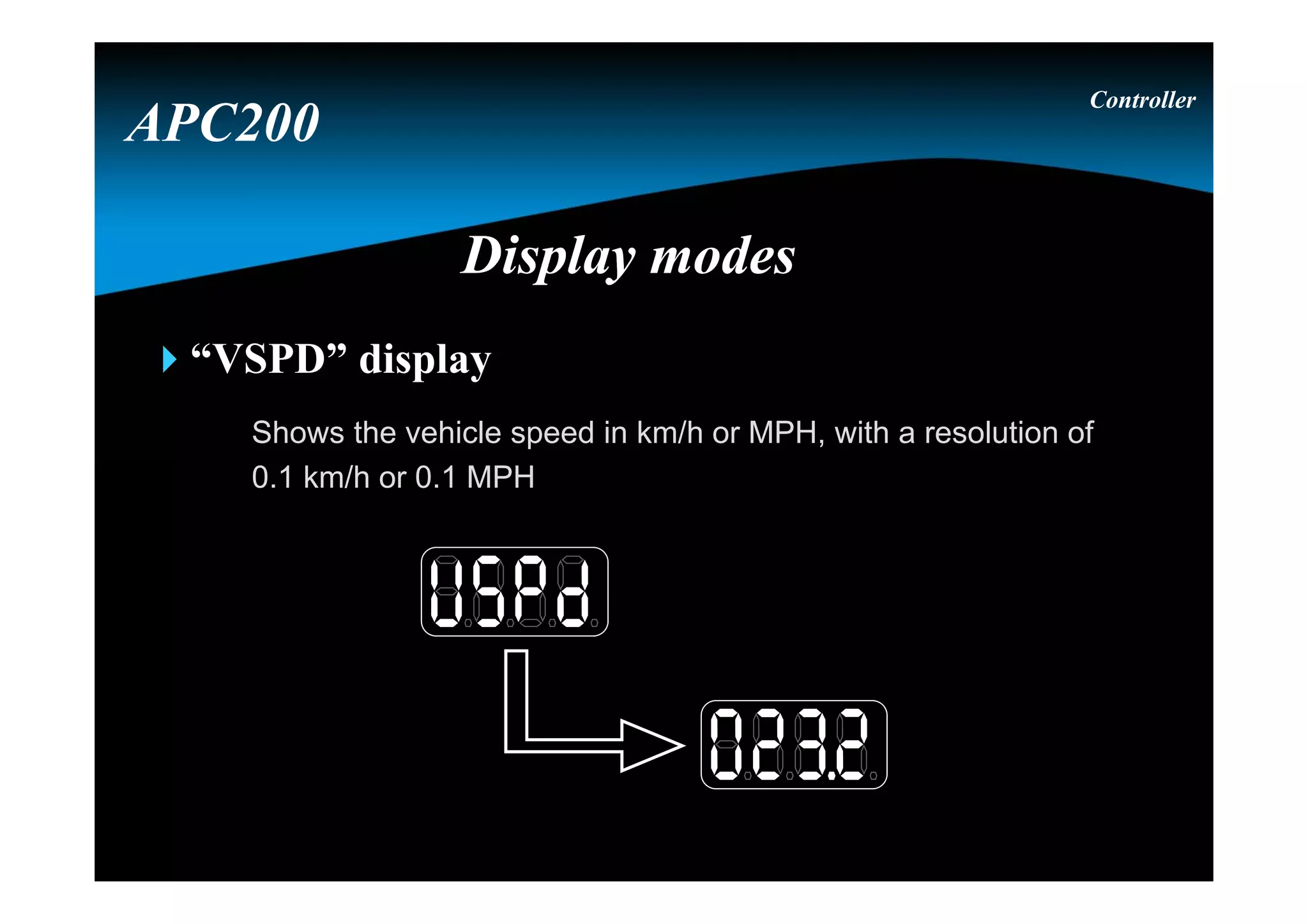
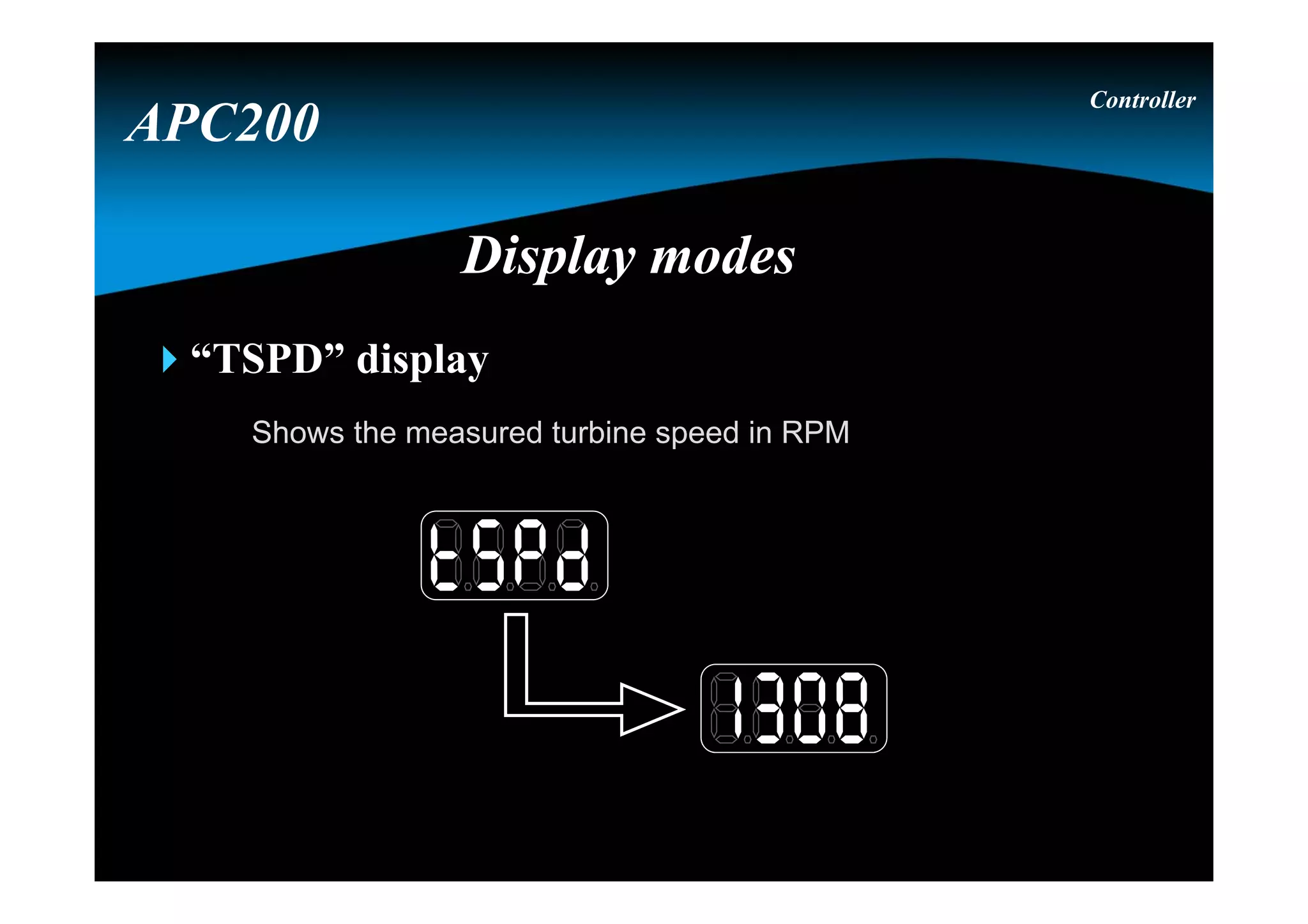
“VSPD” display
Shows thevehicle speed in km/h or MPH, with a resolution of
0.1 km/h or 0.1 MPH
Controller
APC200
Display modesDisplay modes
39.
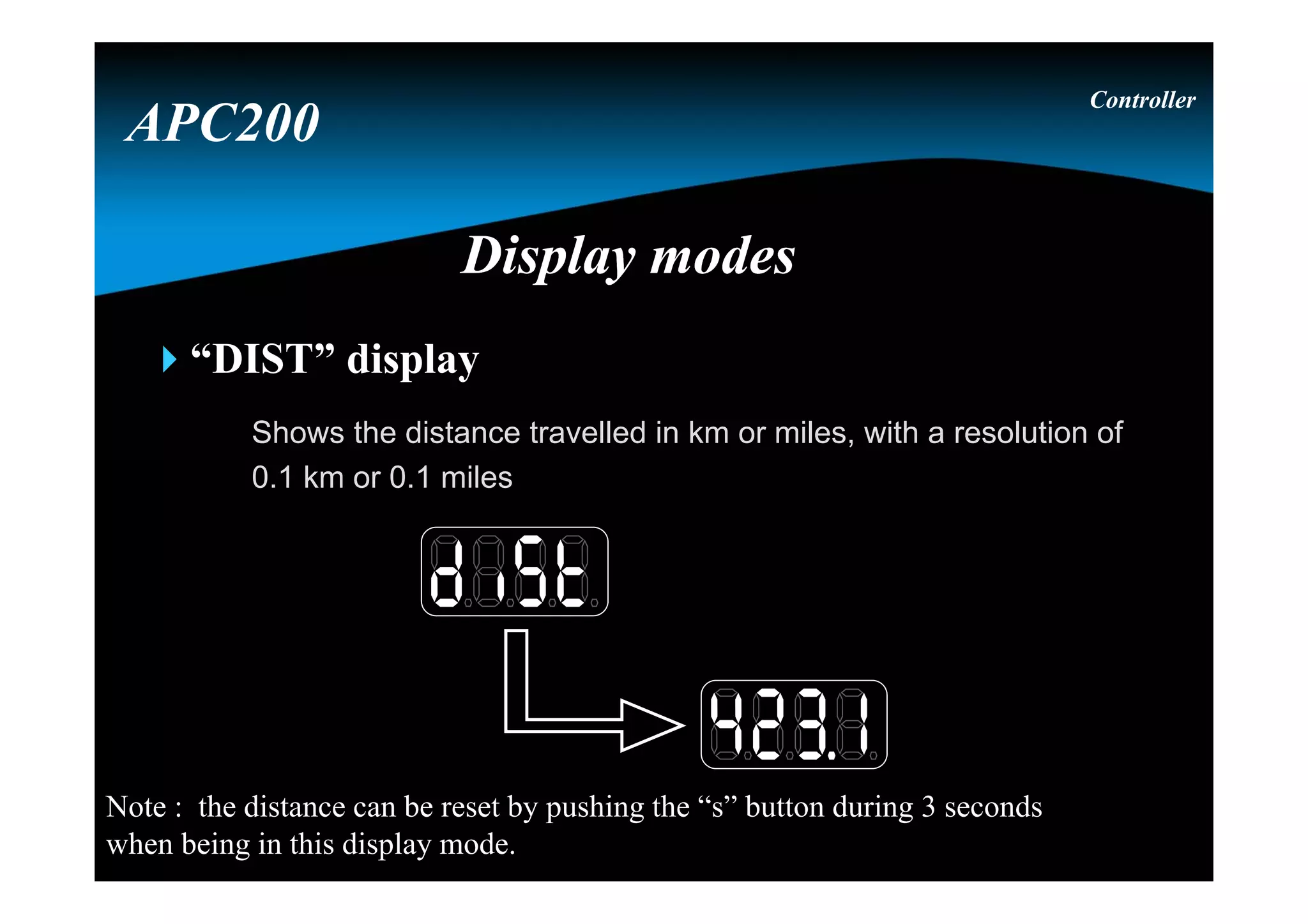
“DIST” display
Shows thedistance travelled in km or miles, with a resolution of
0.1 km or 0.1 miles
Controller
APC200
Display modesDisplay modes
Note : the distance can be reset by pushing the “s” button during 3 seconds
when being in this display mode.
40.
Controller
APC200
Display modesDisplay modes
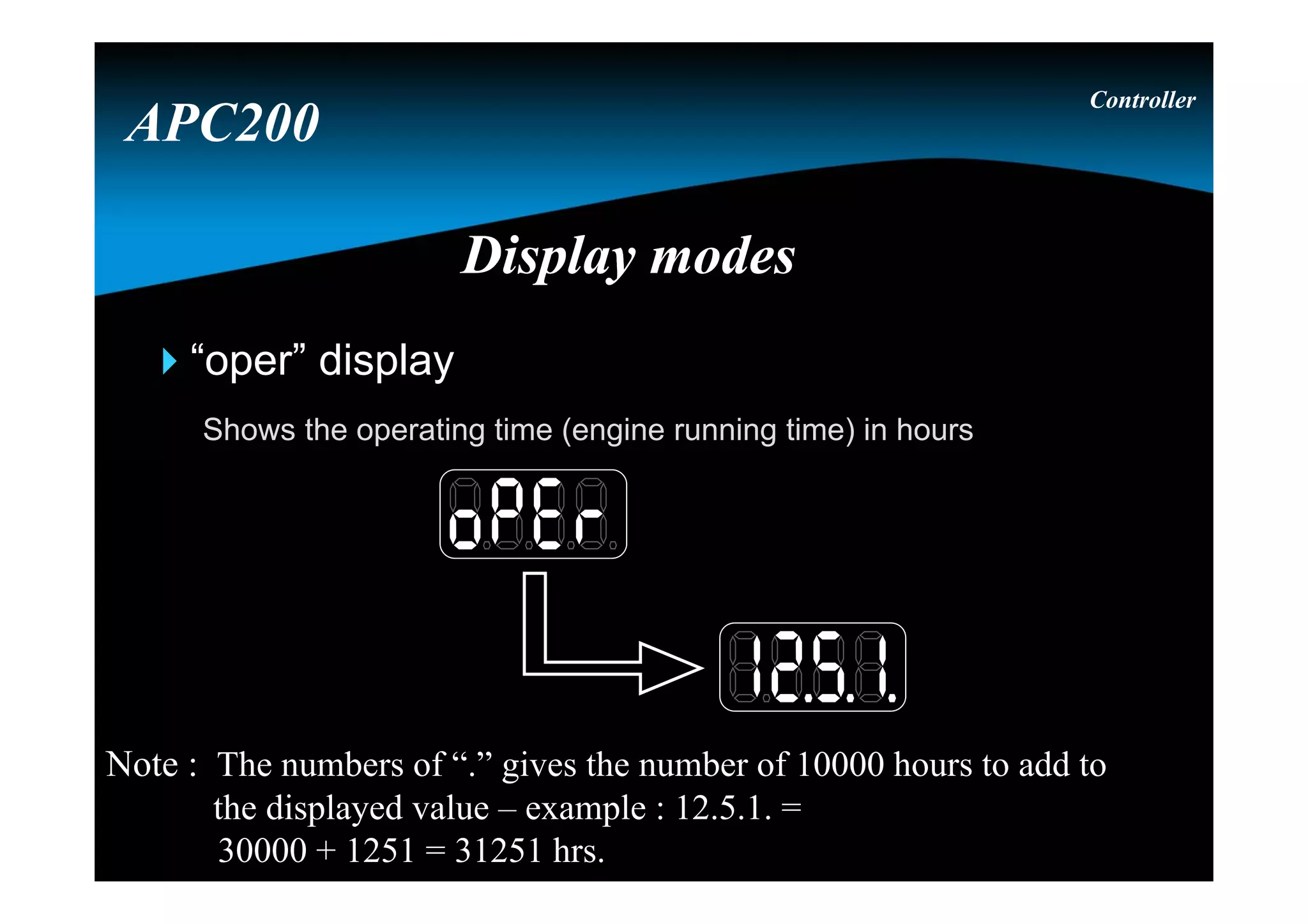
“oper”display
Shows the operating time (engine running time) in hours
Note : The numbers of “.” gives the number of 10000 hours to add to
the displayed value – example : 12.5.1. =
30000 + 1251 = 31251 hrs.
41.
S S S
MM
M
Display modesDisplay modes
Controller
APC200
“SRAT” display
Reflects thecurrent speed ration ( Tspd / Espd ), which is an
important factor in automatic shifting
Controller
APC200
Display modesDisplay modes
47.
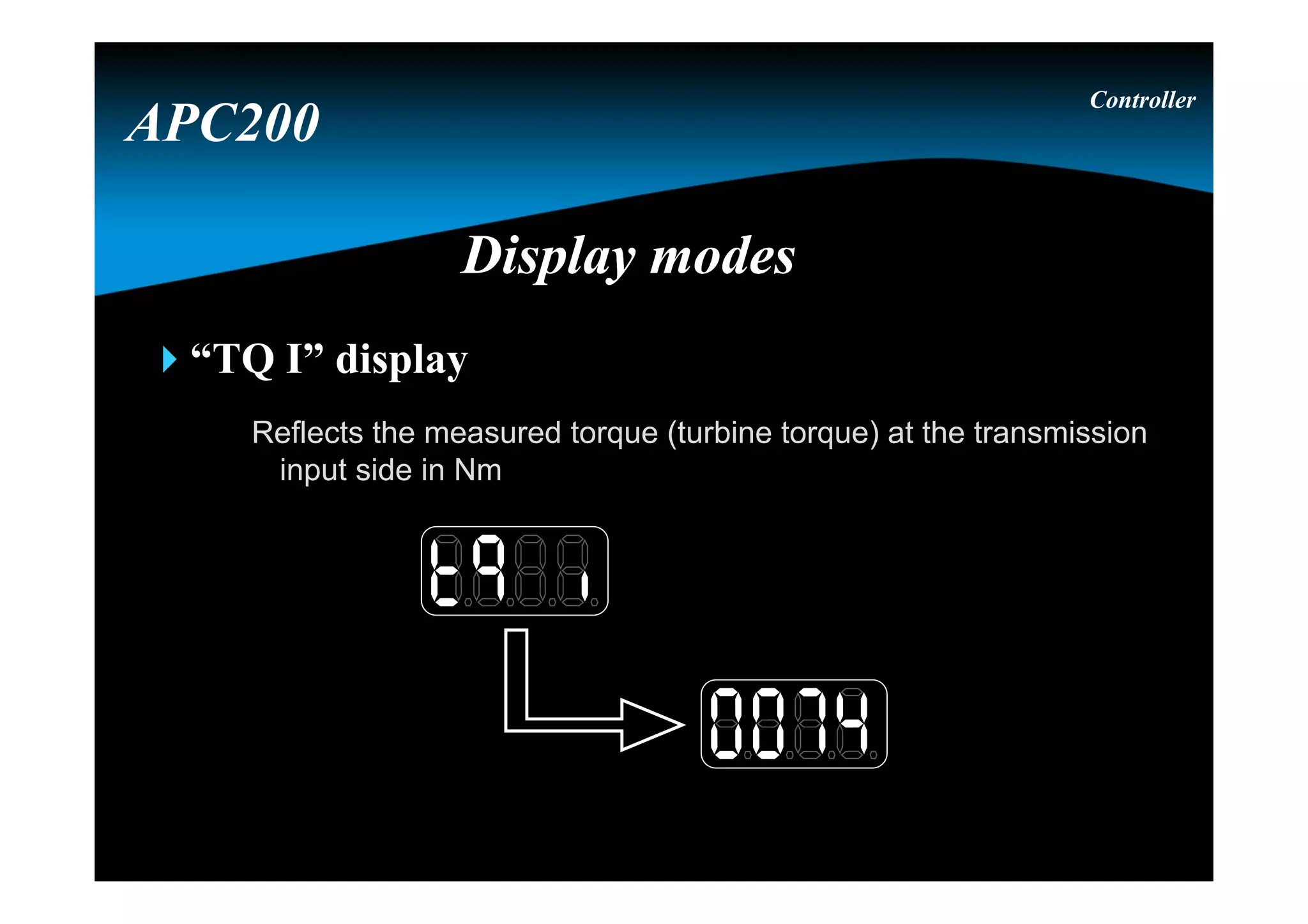
“TQ I” display
Reflectsthe measured torque (turbine torque) at the transmission
input side in Nm
Controller
APC200
Display modesDisplay modes
48.
“TTMP” display
Shows thetransmission sump temperature in °C
Controller
APC200
Display modesDisplay modes
49.
“CTMP” display
Shows theConverter out temperature in °C
Controller
APC200
Display modesDisplay modes
Note : due that the converter out temperature is measured by a
temperature switch : 50 on the display means below 120° C
150 on the display means above 120° C
50.
S S S
MM
M
Display modesDisplay modes
Controller
APC200
51.
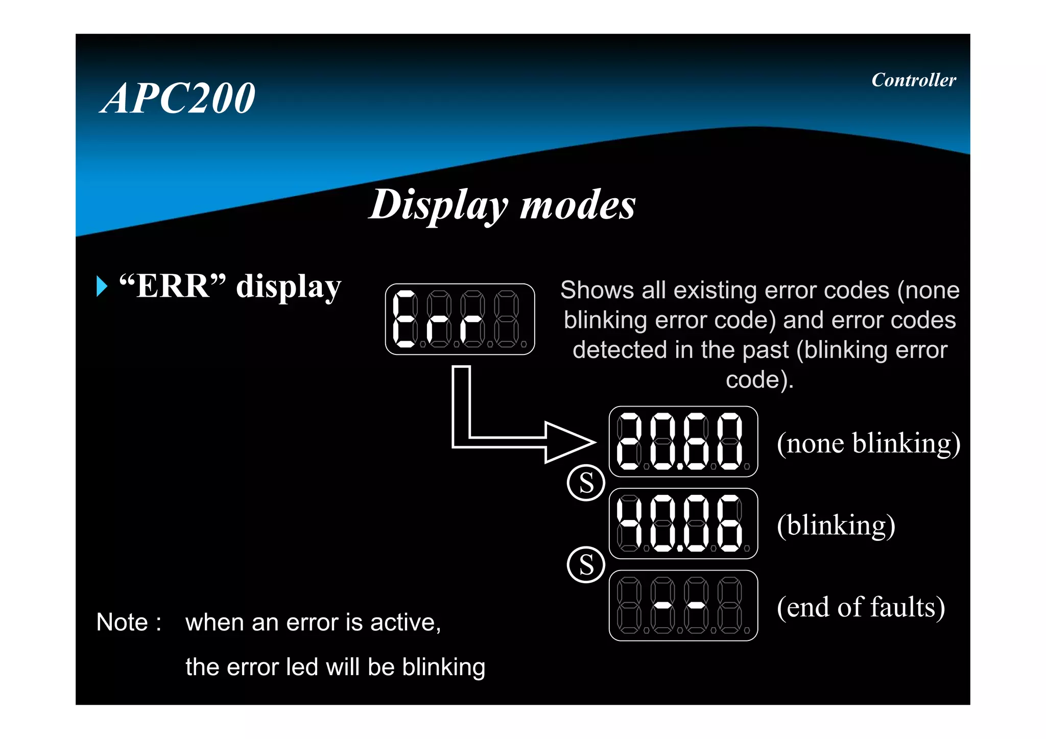
“ERR” display
Controller
APC200
Display modesDisplaymodes
(blinking)
(none blinking)
(end of faults)
S
S
Shows all existing error codes (none
blinking error code) and error codes
detected in the past (blinking error
code).
Note : when an error is active,
the error led will be blinking
52.
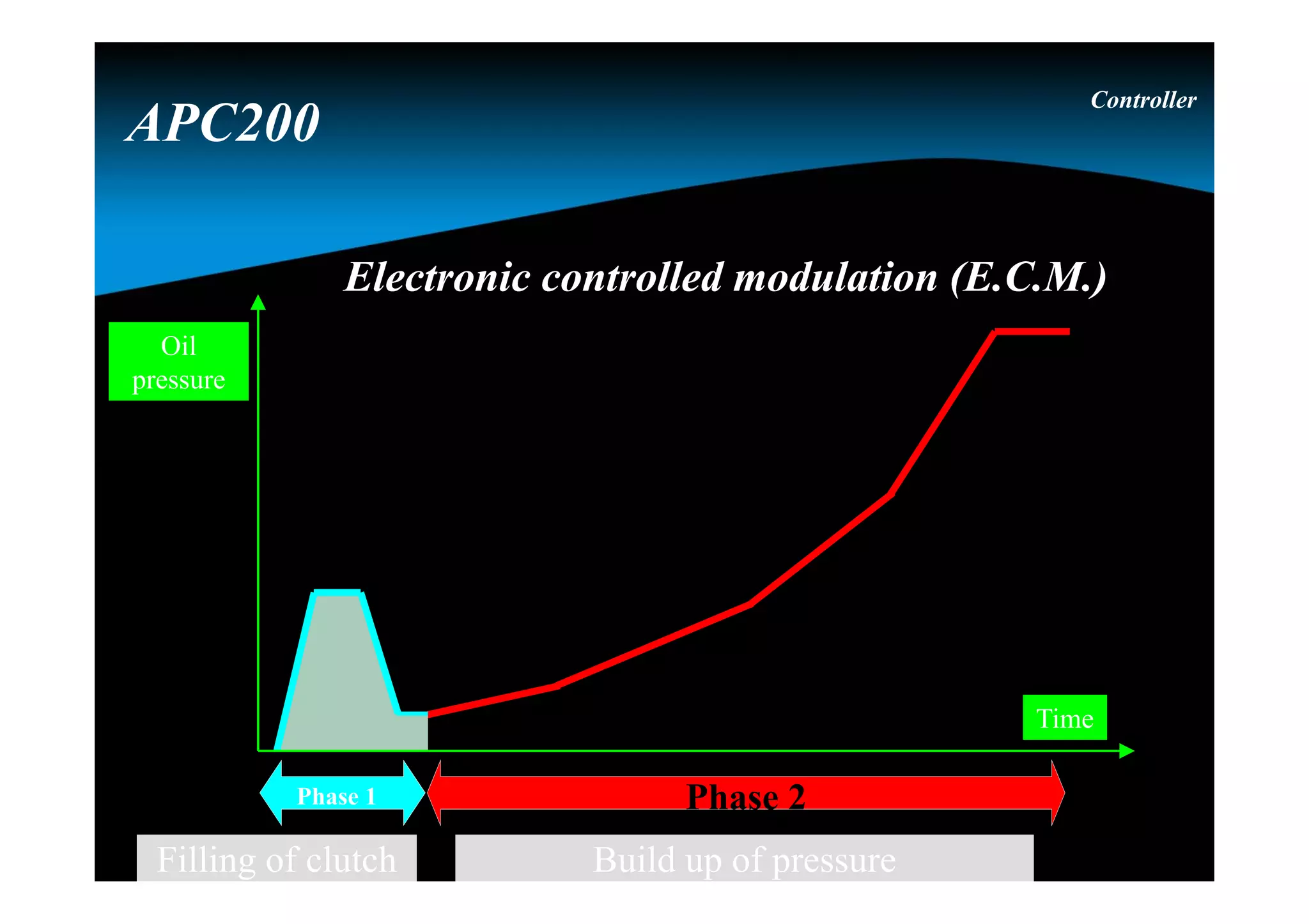
Electronic controlled modulation(E.C.M.)Electronic controlled modulation (E.C.M.)
Controller
APC200
Phase 2
Build up of pressure
Phase 1
Filling of clutch
Time
Oil
pressure
Speed controlled inchingSpeedcontrolled inching
Inch speed as function of brake pedal
position
1
8
00
2
4
6
8
10
0 25 50 75 100
Brake position (%)
Inchspeed(kph)
No Inching
Low Speed
against
brake
Speed
control
No
braking
De-clutch
Controller
APC200
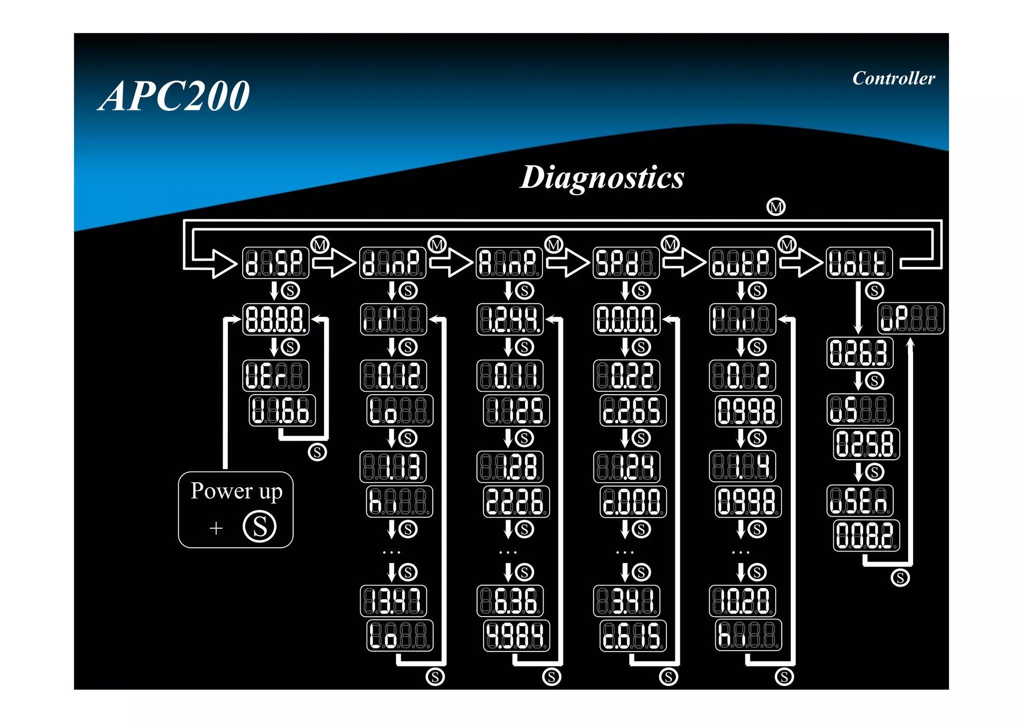
DiagnosticsDiagnostics
M
M M MM M
S
S
S
S
S
S
. . .
S
S
S
S
S
S
. . .
S
S
S
S
S
S
. . .
S
S
S
S
S
S
S
S
S
S
. . .
S
S
S
Power up
+ S
Controller
APC200
58.
Note : forthe firmware version, the display is using a
scrolling text moving to the left (continuously).
Display testDisplay test
Controller
APC200
M
M M M M M
S
S
S
Power up
+ S
DiagnosticsDiagnostics
59.
Digital input
test
Digital input
test
Digitalinput
reference
Digital input
reference
0
1
2
3
4
5
8
9
6
7
10
11
12
13
Note : input 10 till 13 are the 4
analog inputs, which
could be used as digital
inputs
Digital input 3 on
wire 17
Digital input 3 on
wire 17
input not activeinput not active
Controller
APC200
M
M M M M M
S
S
S
S
S
S
. . .
DiagnosticsDiagnostics
60.
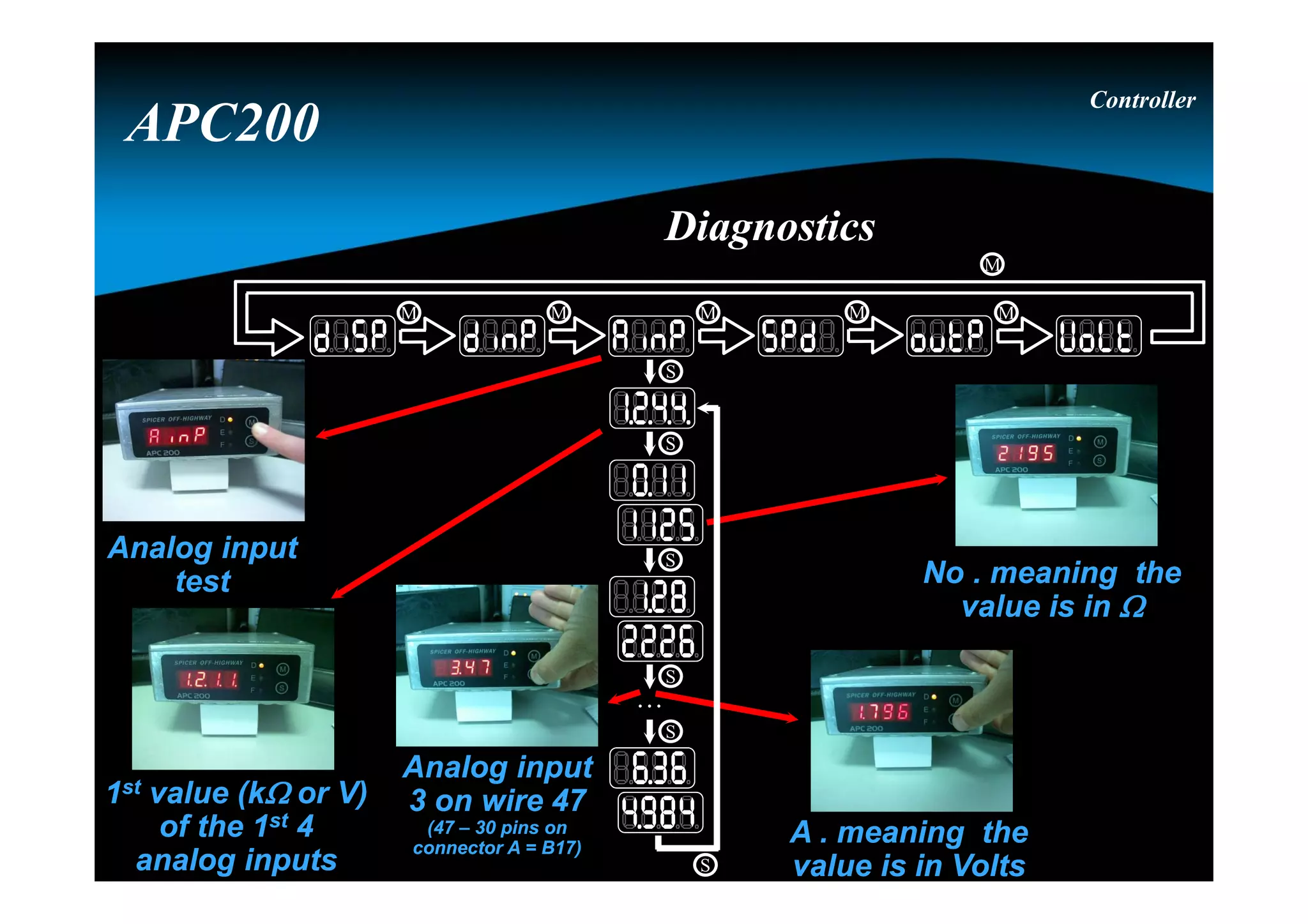
Analog input
test
Analog input
test
1stvalue (k or V)
of the 1st 4
analog inputs
1st value (k or V)
of the 1st 4
analog inputs
No . meaning the
value is in
No . meaning the
value is in
A . meaning the
value is in Volts
A . meaning the
value is in Volts
Analog input
3 on wire 47
(47 – 30 pins on
connector A = B17)
Analog input
3 on wire 47
(47 – 30 pins on
connector A = B17)
Controller
APC200
DiagnosticsDiagnostics
M
M M M M M
S
S
S
S
S
S
. . .
61.
Speed sensor testSpeedsensor test
C informs the
sensor is a current
sensor, value is
expressed in Hz or
kHz (ex.: c2.45)
C informs the
sensor is a current
sensor, value is
expressed in Hz or
kHz (ex.: c2.45)
1st value (kHz)
of the 4 speed
sensors
1st value (kHz)
of the 4 speed
sensors
Speed sensor
0 on wire 22
Speed sensor
0 on wire 22
Controller
APC200
DiagnosticsDiagnostics
M
M M M M M
S
S
S
S
S
S
. . .
62.
Output
test
Output
test
Analog output
Current of997 mA
Analog output
Current of 997 mA
Analog output
3 on wire 8
Analog output
3 on wire 8
Note :
0 till 6 are
analog
outputs, and
7 till 10 are
digital
outputs.
output activeoutput active
Digital output
1 (7 – 6 = 1 ) on
wire 10
Digital output
1 (7 – 6 = 1 ) on
wire 10
Controller
APC200
DiagnosticsDiagnostics
M
M M M M M
S
S
S
S
S
S
. . .
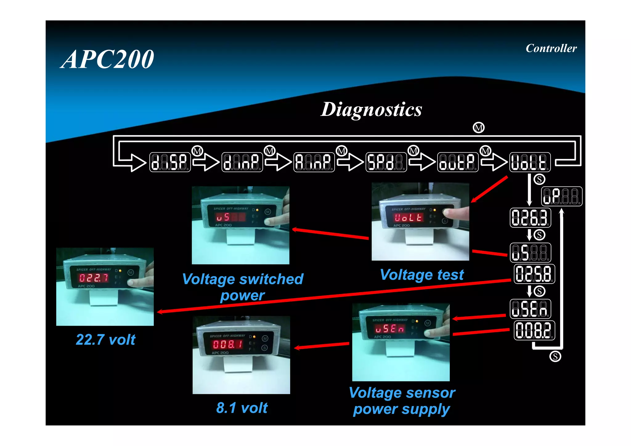
63.
Voltage testVoltage testVoltageswitched
power
Voltage switched
power
Voltage sensor
power supply
Voltage sensor
power supply
22.7 volt22.7 volt
8.1 volt8.1 volt
Controller
APC200
DiagnosticsDiagnostics
M
M M M M M
S
S
S
S
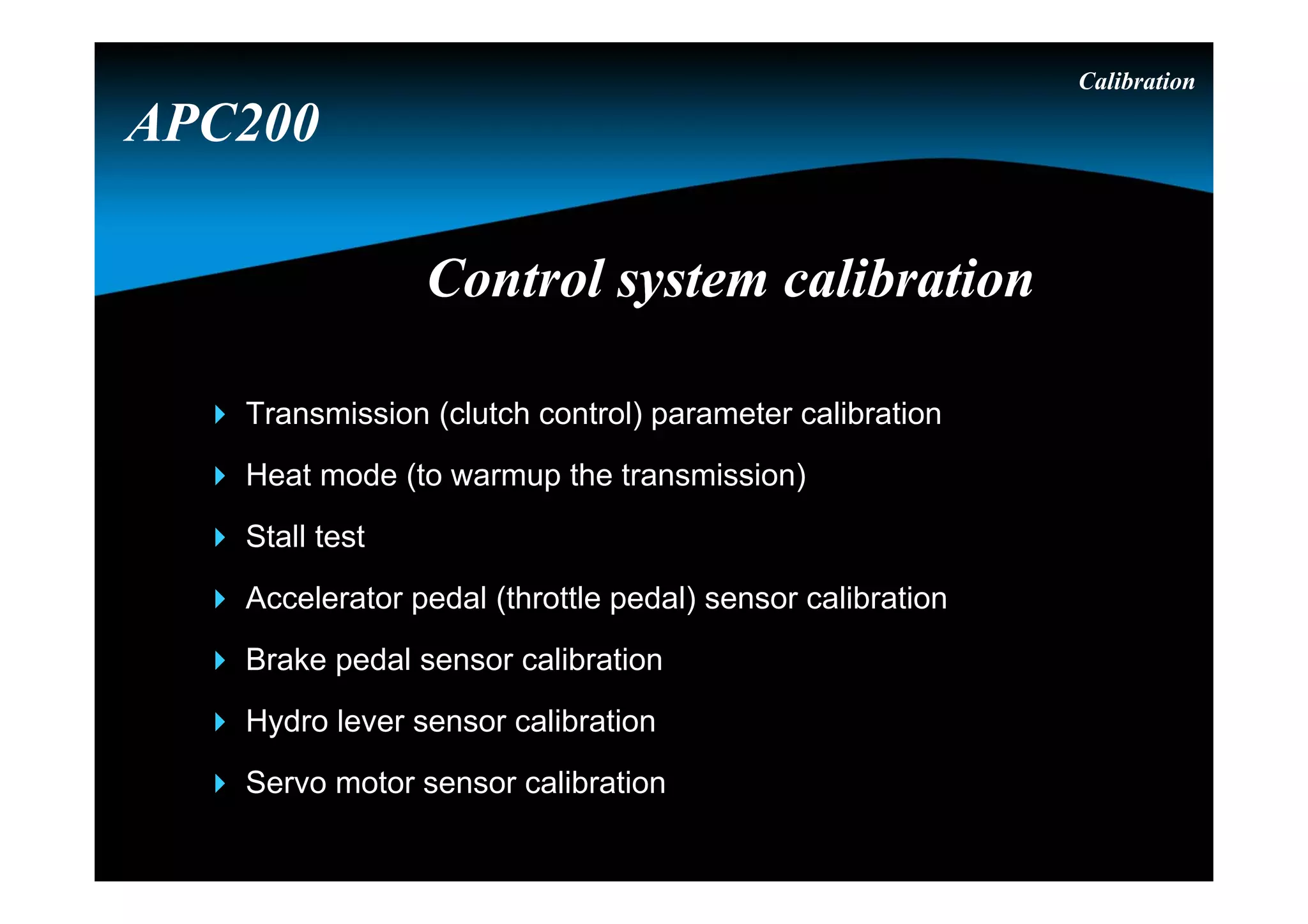
Calibration
The calibration modecan be activated by :
- pushing the “S” button for 15 seconds during powerup
- the GDE (header Global & select for “DisplayMODE” :
“Transcal” & press “F5”)
- Sending a specific CAN message
- using the Dashboard Tool
APC200
Calibration done at the OEMCalibration done at the OEM
69.
Calibration
Select the requestedcalibration mode by pushing the “M” button.
Possible calibration modes :
- “tran” : transmission calibration
- “heat” : transmission warming up
- “thro” : throttle pedal calibration (connected to an analog input)
- “brak” : brake pedal calibration (connected to an analog input)
- “hydr” : hydro lever calibration (connected to an analog input)
- “serv” : servo calibration (connected to the H-bridge)
- “cool” : not used in this application
APC200
Calibration done at the OEMCalibration done at the OEM
70.
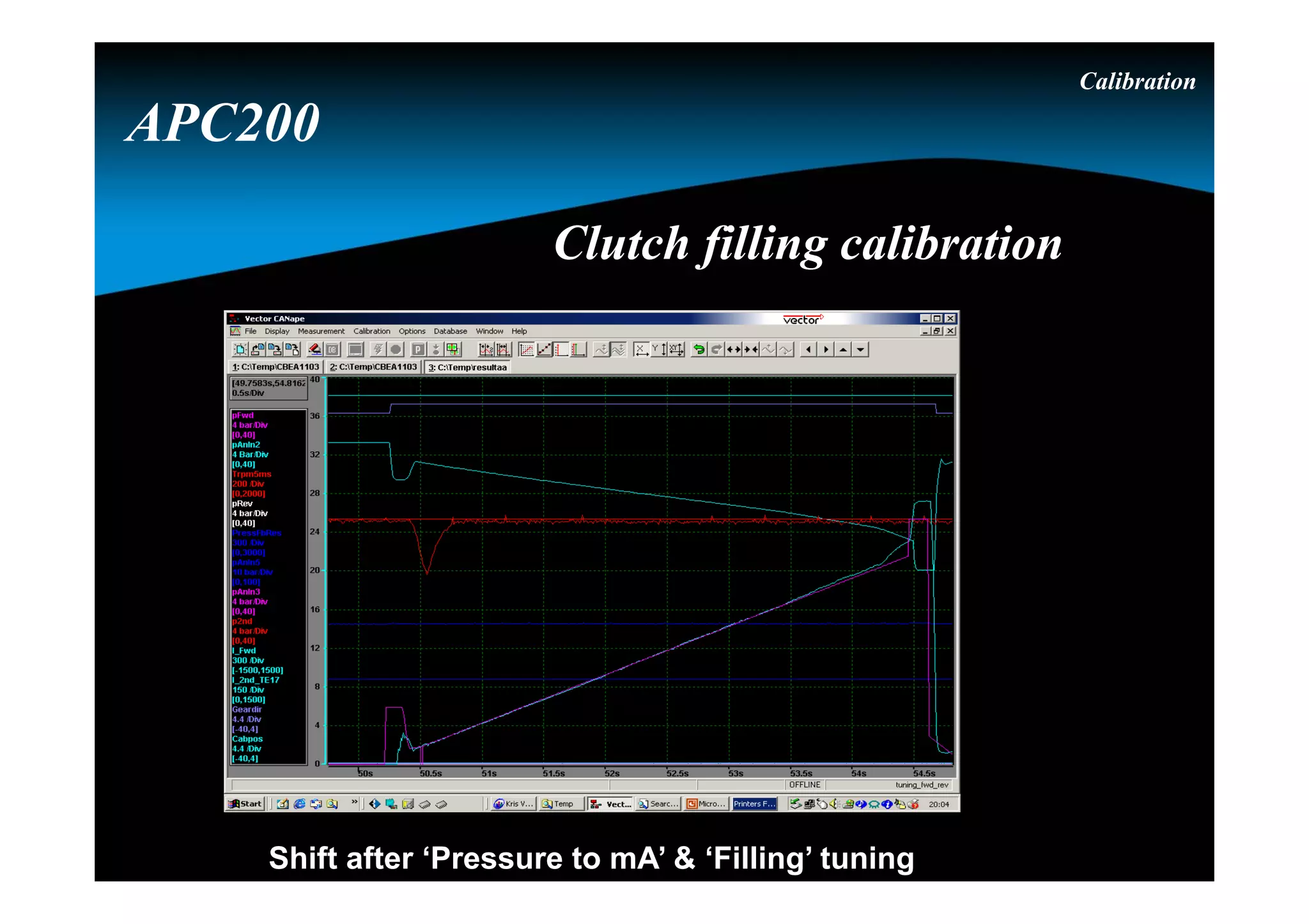
Calibration
Clutch filling “tran”
After selecting the requested calibration mode by pushing the “S”
button the calibration will be started.
During this calibration :
- the parking brake must be activated
- the transmission temperature must be above 60° C
- engine speed must be 800 RPM 200 RPM
To start this calibration the driver will be asked to select forward
(by selecting reverse the calibration will be stopped)
APC200
Calibration done at the OEMCalibration done at the OEM
71.
Calibration
Warming up “heat”
After selecting the requested calibration mode by pushing the “S”
button the calibration will be started.
During this mode :
- only the highest gear can be selected
- the parking brake and brake pedal will not force neutral
- the display will show the sump temerature
When stalling the transmission at full stall : maximum 30 seconds
in gear followed by minimum 15 seconds in neutral
APC200
Calibration done at the OEMCalibration done at the OEM
72.
Calibration
Throttle pedal “thro” (throttle pedal connected to an
analog input)
After selecting the requested calibration mode by pushing the “S”
button the calibration will be started.
During this calibration :
- the idle position is requested
- the full throttle position is requested
By pushing the “S” the driver confirms the requested positions.
APC200
Calibration done at the OEMCalibration done at the OEM
73.
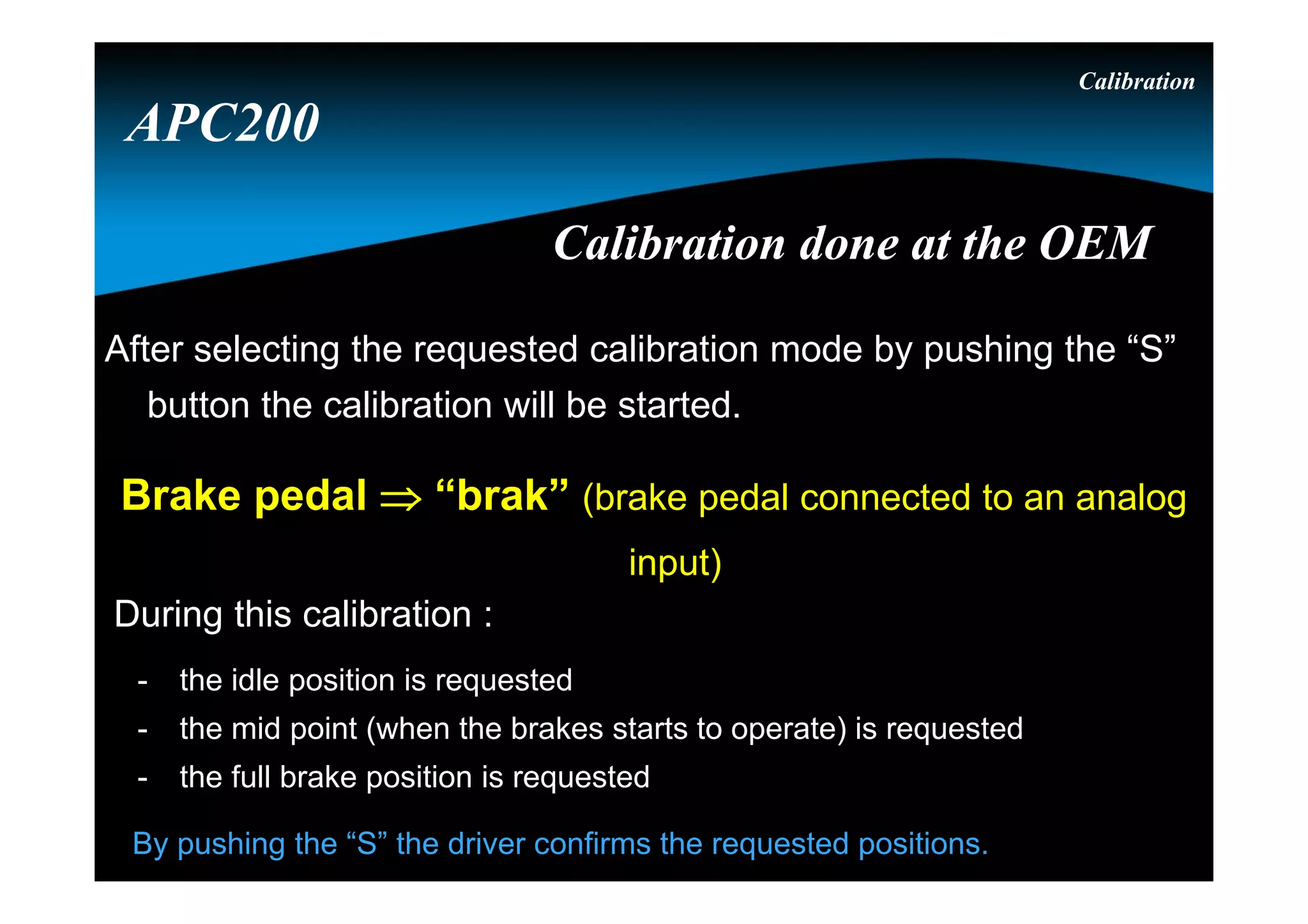
Calibration
Brake pedal “brak” (brake pedal connected to an analog
input)
After selecting the requested calibration mode by pushing the “S”
button the calibration will be started.
During this calibration :
- the idle position is requested
- the mid point (when the brakes starts to operate) is requested
- the full brake position is requested
By pushing the “S” the driver confirms the requested positions.
APC200
Calibration done at the OEMCalibration done at the OEM
74.
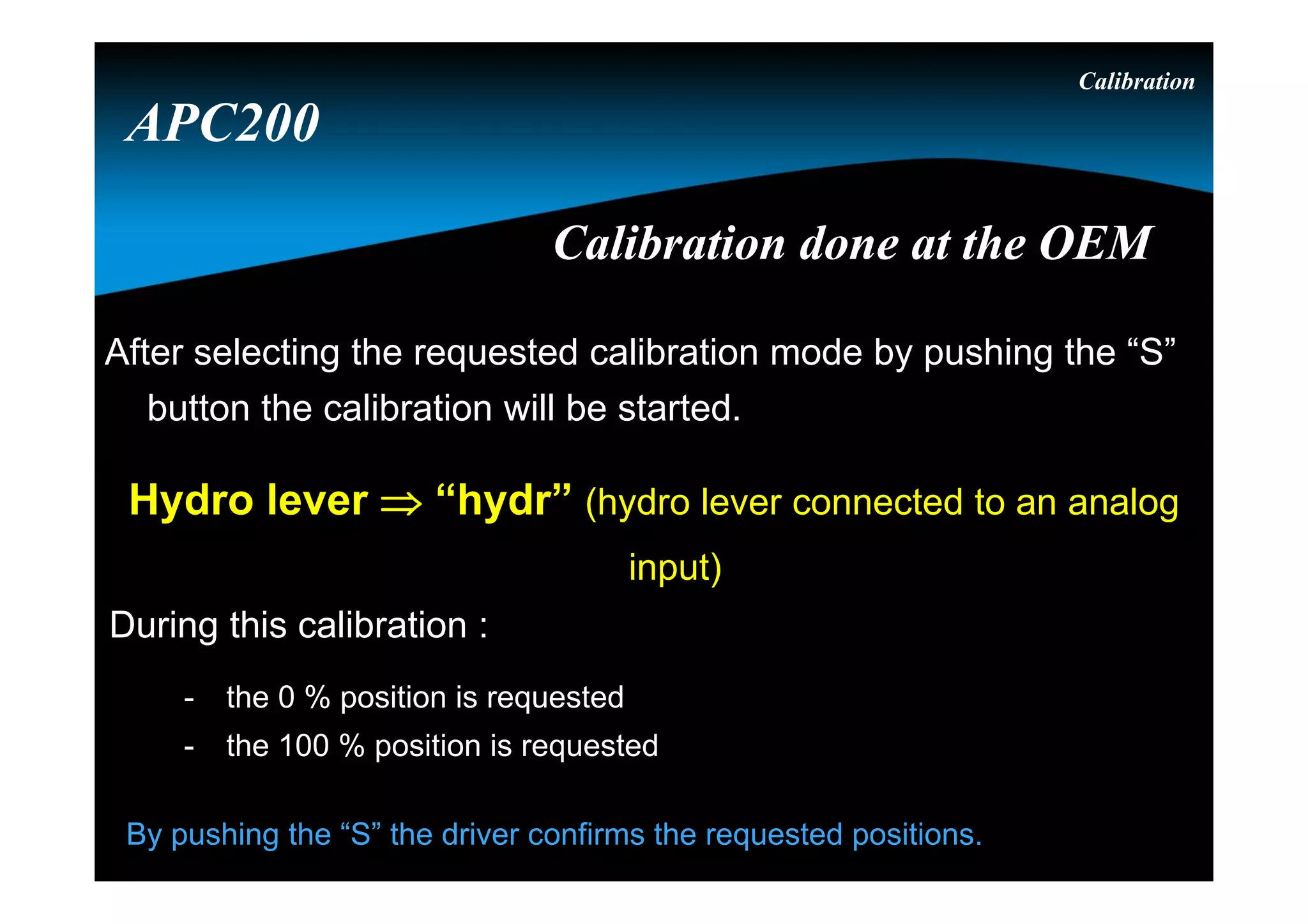
Calibration
Hydro lever “hydr” (hydro lever connected to an analog
input)
After selecting the requested calibration mode by pushing the “S”
button the calibration will be started.
During this calibration :
- the 0 % position is requested
- the 100 % position is requested
By pushing the “S” the driver confirms the requested positions.
APC200
Calibration done at the OEMCalibration done at the OEM
75.
Calibration
Servo “serv”(servo motor connected to the H-bridge)
After selecting the requested calibration mode by pushing the “S”
button the calibration will be started.
During this calibration :
- the APC200 will calibrate the idle position
- the APC200 will calibrate the full throttle position
APC200
Calibration done at the OEMCalibration done at the OEM